Page 1860 of 2389

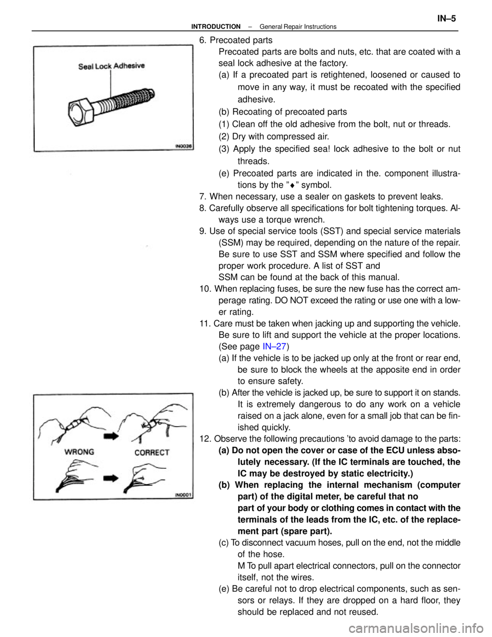
6. Precoated parts
Precoated parts are bolts and nuts, etc. that are coated with a
seal lock adhesive at the factory.
(a) If a precoated part is retightened, loosened or caused to
move in any way, it must be recoated with the specified
adhesive.
(b) Recoating of precoated parts
(1) Clean off the old adhesive from the bolt, nut or threads.
(2) Dry with compressed air.
(3) Apply the specified sea! lock adhesive to the bolt or nut
threads.
(e) Precoated parts are indicated in the. component illustra-
tions by the ºrº symbol.
7. When necessary, use a sealer on gaskets to prevent leaks.
8. Carefully observe all specifications for bolt tightening torques. Al-
ways use a torque wrench.
9. Use of special service tools (SST) and special service materials
(SSM) may be required, depending on the nature of the repair.
Be sure to use SST and SSM where specified and follow the
proper work procedure. A list of SST and
SSM can be found at the back of this manual.
10. When replacing fuses, be sure the new fuse has the correct am-
perage rating. DO NOT exceed the rating or use one with a low-
er rating.
11. Care must be taken when jacking up and supporting the vehicle.
Be sure to lift and support the vehicle at the proper locations.
(See page IN±27)
(a) If the vehicle is to be jacked up only at the front or rear end,
be sure to block the wheels at the apposite end in order
to ensure safety.
(b) After the vehicle is jacked up, be sure to support it on stands.
It is extremely dangerous to do any work on a vehicle
raised on a jack alone, even for a small job that can be fin-
ished quickly.
12. Observe the following precautions 'to avoid damage to the parts:
(a) Do not open the cover or case of the ECU unless abso-
lutely necessary. (If the IC terminals are touched, the
IC may be destroyed by static electricity.)
(b) When replacing the internal mechanism (computer
part) of the digital meter, be careful that no
part of your body or clothing comes in contact with the
terminals of the leads from the IC, etc. of the replace-
ment part (spare part).
(c) To disconnect vacuum hoses, pull on the end, not the middle
of the hose.
M To pull apart electrical connectors, pull on the connector
itself, not the wires.
(e) Be careful not to drop electrical components, such as sen-
sors or relays. If they are dropped on a hard floor, they
should be replaced and not reused.
± INTRODUCTIONGeneral Repair InstructionsIN±5
Page 2254 of 2389
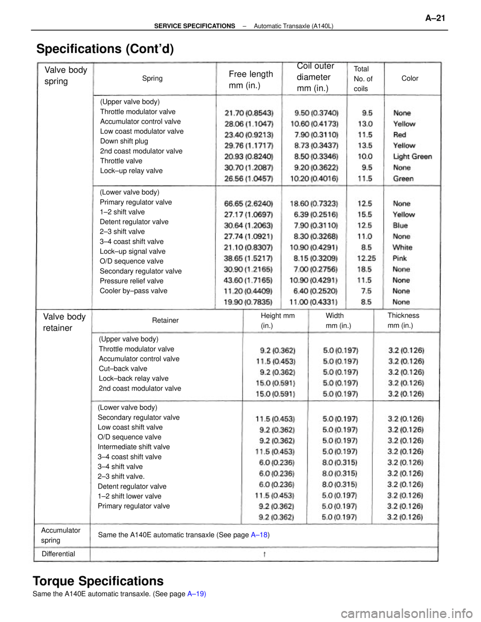
(Upper valve body)
Throttle modulator valve
Accumulator control valve
Low coast modulator valve
Down shift plug
2nd coast modulator valve
Throttle valve
Cut±back valve
Lock±up relay valve
(Lower valve body)
Primary regulator valve
1±2 shift valve
2±3 shift valve
3±4 shift valve
Lock±up signal valve
Secondary regulator valve
Pressure relief valve
Cooler by±pass valvePlanetary pinion gear thrust clearance
Ring gear flange bushing inside diameterPiston stroke
Drum bushing inside diamater
Flange thickness
Direct clutch piston stroke
Direct clutch bushing inside diameterPlanetary pinion gear thrust clearance
Planetary pinion gear thrust clearance
Specifications (Cont'd)
Piston stroke
Flange thickness
Counter drive gear preload
Coil outer
diameter
mm (in.)
Rear plane-
tary gearFront plane-
tary gear
Free length
mm (in.) Valve body
springOverdrive
unit
Total
No. of
coifs
Forward
clutchDirect clutch
Spring
Color
± SERVICE SPECIFICATIONSAutomatic Transaxle (Al 40E)A±17
Page 2255 of 2389
(Lower valve body)
Primary regualtor valve
2±3 shift valve
1±2 shift valve
3±4 shift valve
Secondary regulator valve
Lock±up signal valve (Upper valve body)
Throttle modulator valve
Accumulator control valve
Cut±back valve
Lock±up relay valve
2nd coast modulator valve
Pinion to side gear backlash
Side gear thrust washer thickness
Side bearing adjusting shim thickness
Specifications (Cont'd)
Drive pinion preload (at starting)
Total preload (at starting)Coil outer
diameter mm
(in.) Accumulator
springFree length
mm (in.) Valve body
RetainerThickness
(mm (in.)
Total
No. of
coils
Height mm
(in.)Width
mm (in.)
DifferentialRetainer
Spring
Color
± SERVICE SPECIFICATIONSAutomatic Transaxle (A140E)A±18
Page 2258 of 2389

(Lower valve body)
Secondary regulator valve
Low coast shift valve
O/D sequence valve
Intermediate shift valve
3±4 coast shift valve
3±4 shift valve
2±3 shift valve.
Detent regulator valve
1±2 shift lower valve
Primary regulator valve(Lower valve body)
Primary regulator valve
1±2 shift valve
Detent regulator valve
2±3 shift valve
3±4 coast shift valve
Lock±up signal valve
O/D sequence valve
Secondary regulator valve
Pressure relief valve
Cooler by±pass valve(Upper valve body)
Throttle modulator valve
Accumulator control valve
Low coast modulator valve
Down shift plug
2nd coast modulator valve
Throttle valve
Lock±up relay valve
(Upper valve body)
Throttle modulator valve
Accumulator control valve
Cut±back valve
Lock±back relay valve
2nd coast modulator valve
Torque Specifications
Same the A140E automatic transaxle. (See page A±19) Same the A140E automatic transaxle (See page A±18)
Specifications (Cont'd)
Coil outer
diameter
mm (in.)
Accumulator
spring
Free length
mm (in.) Valve body
spring
Thickness
mm (in.)Valve body
retainer
Total
No. of
coils
Height mm
(in.)Width
mm (in.)
DifferentialColor
Retainer Spring
± SERVICE SPECIFICATIONSAutomatic Transaxle (A140L)A±21
Page 2260 of 2389

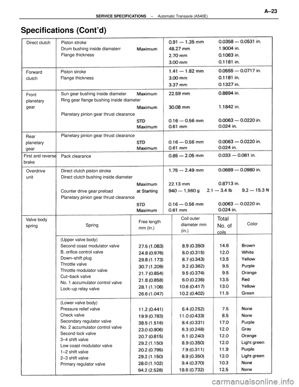
(Lower valve body)
Pressure relief valve
Check valve
Secondary regulator valve
No. 2 accumulator control valve
Second lock valve
3±4 shift valve
Low coast modulator valve
1±2 shift valve
2±3 shift valve
Primary regulator valve(Upper valve body)
Second coast modulator valve
B, orifice control valve
Down±shift plug
Throttle valve
Throttle modulator valve
Cut±back vaIve
No. 1 accumulator control valve
Lock±up relay valvePiston stroke
Drum bushing inside diamaterr
Flange thickness
Sun gear bushing inside diameter
Ring gear flange bushing inside diameter
Counter drive gear preload
Planetary pinion gear thrust clearanceDirect clutch piston stroke
Direct clutch bushing inside diameter Planetary pinion gear thrust clearancePlanetary pinion gear thrust clearance
Specifications (Cont'd)
Piston stroke
Flange thickness
Coil outer
diameter mm
(in.) Rear
planetary
gearFront
planetary
gear Forward
clutch
First and reverse
brake
Free length
mm (in.) Valve body
springOverdrive
unit
Total
No. of
coils Pack clearance Direct clutch
SpringColor
± SERVICE SPECIFICATIONSAutomatic Transaxle (A540E)A±23
Page 2261 of 2389
(Lower valve body)
Primary regulator valve
Secondary regulator valve
No. 2 accumulator control valve
Second lock valve
Low coast modulator valve
1±2 shift valve
2±3 shift valve
3±4 shift valve (Upper valve body)
Lock±up relay valve
Throttle modulator valve
Second coast modulator valve
Cut±back valve
No. 1 accumulator control valve
B, orifice contron valve
Pinion to side gear backlash
Side gear thrust washer thickness
Specifications (Cont'd)
Side bearing adjusting shim thicknessDrive pinion preload (at startin )
Total preload (at starting)Coil outer
diameter mm
(in.) Accumulator
springFree length
mm (in.) Valve body
retainerThickness
(mm (in.)
Total
No. of
coils Width
mm (in.) Height mm
(in.)
DifferentialRetainer
SpringColor
± SERVICE SPECIFICATIONSAutomatic Transaxle (A540E)A±24
Page 2310 of 2389

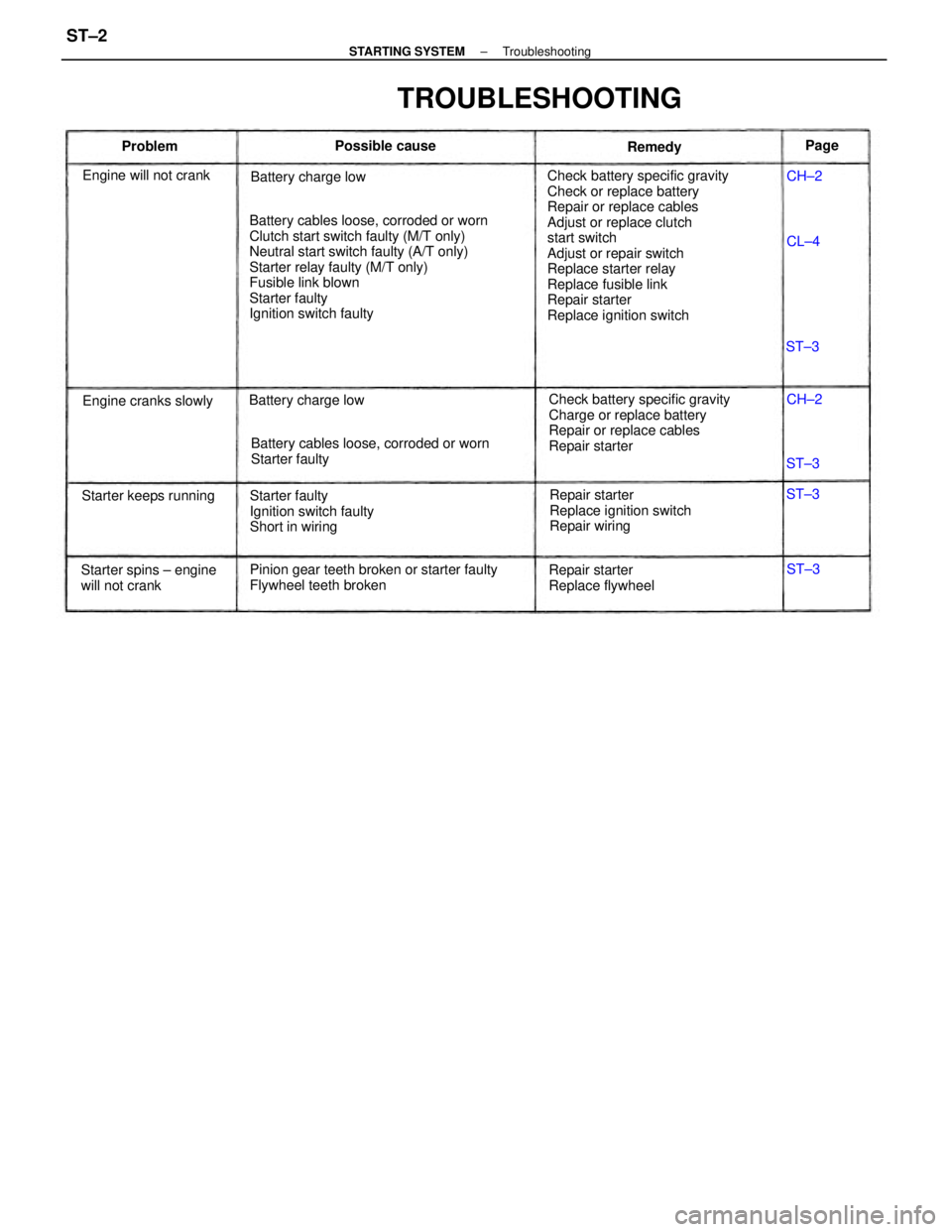
Check battery specific gravity
Check or replace battery
Repair or replace cables
Adjust or replace clutch
start switch
Adjust or repair switch
Replace starter relay
Replace fusible link
Repair starter
Replace ignition switch Battery cables loose, corroded or worn
Clutch start switch faulty (M/T only)
Neutral start switch faulty (A/T only)
Starter relay faulty (M/T only)
Fusible link blown
Starter faulty
Ignition switch faulty
Check battery specific gravity
Charge or replace battery
Repair or replace cables
Repair starter
Pinion gear teeth broken or starter faulty
Flywheel teeth brokenBattery cables loose, corroded or worn
Starter faulty
Repair starter
Replace ignition switch
Repair wiring Starter faulty
Ignition switch faulty
Short in wiring
TROUBLESHOOTING
Starter spins ± engine
will not crankRepair starter
Replace flywheel Engine will not crank
Starter keeps runningBattery charge low
Engine cranks slowlyBattery charge lowPossible cause
Remedy ProblemPage
CH±2
CH±2
ST±3 ST±3
ST±3
ST±3 CL±4
± STARTING SYSTEMTroubleshootingST±2
Page 2324 of 2389
1. INSPECT RELAY CONTINUITY
(a) Using an ohmmeter, check that there is continuity between
terminals 1 and 3.
(b) Check that there is no continuity between terminals 2
and 4.
If continuity is not as specified, replace the relay.
2. INSPECT RELAY OPERATION
(a) Apply battery voltage across terminals 1 and 3.
(b) Using an ohmmeter, check that there is continuity between
terminals 2 and 4.
If operation is not as specified, replace the relay.
STARTER RELAY (MT only)
INSPECTION OF STARTER RELAY
LOCATION: In the left cowl side.
CLUTCH START SWITCH (MT only)
(See page CL±4)
± STARTING SYSTEMStarter Relay (M T only)ST±16