1973 DATSUN B110 ECU
[x] Cancel search: ECUPage 216 of 513
Removal
I
t
is
recommended
that
the
door
be
removed
from
the
body
with
the
door
hinges
attached
on
the
door
although
the
door
may
be
removed
from
the
body
with
or
without
the
hinges
attached
on
the
door
Front
door
Remove
the
package
tray
2
Remove
the
door
hinge
service
hole
cover
from
the
dash
side
trim
3
With
the
door
fully
opened
support
the
door
by
applying
a
stand
or
jack
beneath
the
door
so
that
the
door
does
not
drop
off
Note
Apply
a
piece
of
rag
between
the
door
and
stand
so
that
the
door
panel
is
protected
from
damaging
4
Remove
the
door
hinge
installation
bolts
at
the
body
side
by
the
use
of
a
box
wrench
and
remove
the
door
from
the
body
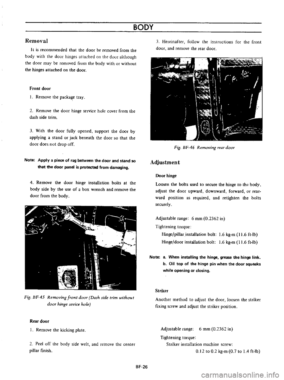
Fig
BF
45
Removing
front
door
Dash
side
trim
without
door
hinge
sevice
hole
Rear
door
Remove
the
kicking
plate
2
Peel
off
the
body
side
welt
and
remove
the
center
pillar
finish
BODY
3
Hereinafter
follow
the
instructions
for
the
front
door
and
remove
the
rear
door
11
I
fl
C
I
r
r
I
W
I
r
I
I
dl
J
Ik
I
h
I
l
i
J
n
Fig
BF
46
Removing
rear
door
Adjustment
Door
hinge
Loosen
the
bolts
used
to
secure
the
hinge
to
the
body
adjust
the
door
upward
downward
forward
or
rear
ward
position
as
required
and
retighten
the
bolts
securely
Adjustable
range
6
mm
0
2362
in
Tightening
torque
Hinge
pillar
installation
bolt
1
6
kg
m
11
6
ft
lb
Hinge
door
installation
bolt
1
6
kg
m
11
6
ft
lb
Note
a
When
installing
the
hinge
grease
the
hinge
link
b
Oil
top
of
the
hinge
pin
when
the
door
squeaks
while
opening
or
closing
Striker
Another
method
to
adjust
the
door
loosen
the
striker
fixing
screw
and
adjust
the
striker
position
Adjustable
range
6
mm
0
2362
in
Tightening
torque
Striker
installation
machine
screw
0
12
to
0
2
kg
m
0
7
to
I
4
ft
lb
BF
26
Page 217 of 513
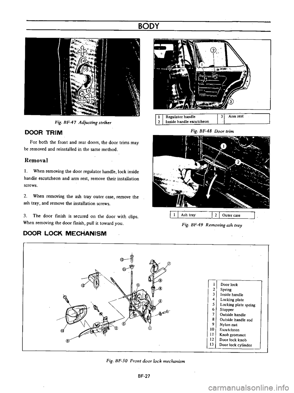
Fig
BF
47
Adjusting
striker
DOOR
TRIM
For
both
the
front
and
rear
doon
the
door
trims
may
be
removed
and
reinsbJled
in
the
same
method
Removal
I
When
removing
the
door
regulator
handle
lock
inside
handle
escutcheon
and
arm
rest
remove
their
installation
screws
2
When
removing
the
ash
tray
outer
case
remove
the
ash
tray
and
remove
the
installation
screws
3
The
door
finish
is
secured
on
the
door
with
clips
When
removing
the
door
finish
pull
it
toward
you
DOOR
LOCK
MECHANISM
BODY
I
I
Regulator
handle
Imide
handle
escu
tcheon
131
Armrest
Fig
BF
48
Door
trim
III
I
2
Outer
case
Ash
tray
Fig
BF
49
Removing
ash
tray
1
1
Door
lock
2
Spring
3
Inside
handle
4
Locking
plate
5
Locking
plate
spring
6
Stopper
7
Outside
handle
8
Ou
tside
handle
rod
9
Nylon
nut
10
Escu
tchcon
11
Knob
grommet
12
Door
lock
knob
13
Door
lock
cylinder
Fig
BF
50
Front
door
lock
mechanism
SF
27
Page 218 of 513
IT
f
r
J
e
@
@
BODY
Door
lock
2
I
nside
handle
3
Escu
tcheon
4
Door
lock
knob
5
Knob
grommet
Front
door
lock
removal
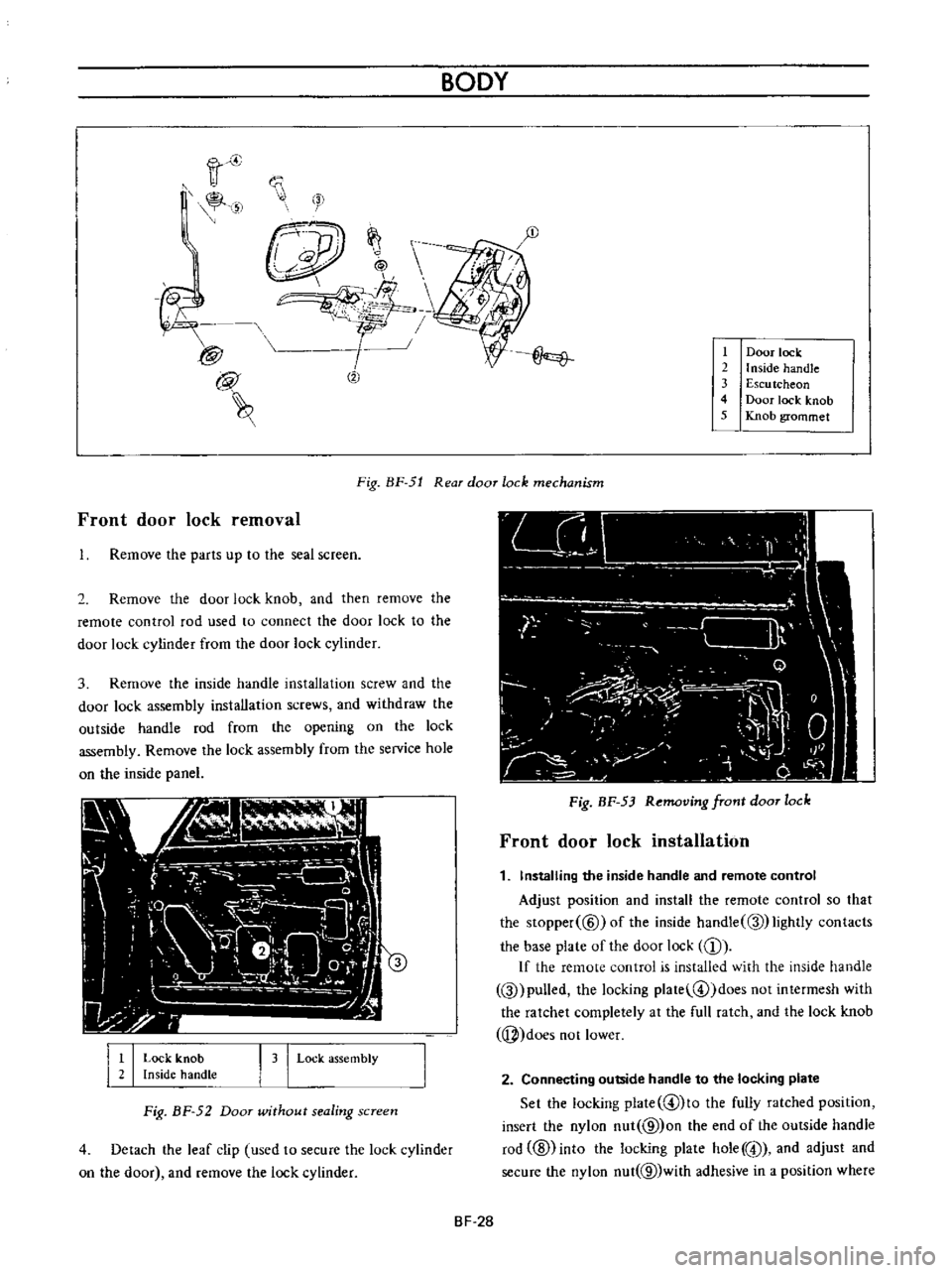
Fig
BF
51
Rear
door
lock
mechanism
Remove
the
parts
up
to
the
seal
screen
2
Remove
the
door
lock
knob
and
then
remove
the
remote
control
rod
used
to
connect
the
door
lock
to
the
door
lock
cylinder
from
the
door
lock
cylinder
3
Remove
the
inside
handle
installation
screw
and
the
door
lock
assembly
installation
screws
and
withdraw
the
outside
handle
rod
from
the
opening
on
the
lock
assembly
Remove
the
lock
assembly
from
the
service
hole
on
the
inside
panel
I
I
Lock
knob
Inside
handLe
I
3
I
Lock
assembly
Fig
BF
52
Door
wUhout
sealing
screen
4
Detach
the
leaf
clip
used
to
secure
the
lock
cylinder
on
the
door
and
remove
the
lock
cylinder
Fig
BF
53
Removing
front
door
lock
Front
door
lock
installation
1
Installing
the
inside
handle
and
remote
control
Adjust
position
and
install
the
remote
control
so
that
the
Slopper
@
ofthe
inside
handle
Q
lightly
contacts
the
base
plate
of
the
door
lock
CD
If
the
remote
control
is
installed
with
the
inside
handle
Q
pulled
the
locking
plate
@
doesnotintermesh
with
the
ratchet
completely
at
the
full
ratch
and
the
lock
knob
j
does
not
lower
2
Connecting
outside
handle
to
the
locking
plate
Set
the
locking
plate
@lto
the
fully
ratched
position
insert
the
nylon
nut
@
on
the
end
of
the
outside
handle
rod
ID
into
the
locking
plate
hole
@
and
adjust
and
secure
the
nylon
nut
@
with
adhesive
in
a
position
where
BF
28
Page 219 of 513
the
outside
handle
rod
@
is
provided
with
2
to
3
mm
0
0787
to
0
1181
in
play
in
the
stroke
If
the
nylon
nut
@
is
positioned
too
low
the
locking
plate
@
is
depressed
at
the
full
ratch
the
locking
plate
does
not
intermesh
with
the
ratchet
completely
and
the
knob
cannot
be
locked
If
play
in
stroke
of
the
outside
handle
rod
@
is
excessive
may
be
unlocked
up
to
5
mm
0
1967
in
stroke
of
the
outside
handle
will
be
insufficient
If
the
nylon
nut
is
loosened
the
above
described
trouble
occurs
Be
sure
to
secure
the
nut
completely
by
means
of
adhesive
Check
the
springs
@
and
@
for
rust
and
replace
as
required
Tightening
torque
Door
lock
installation
screw
0
12
to
0
2
kg
m
0
9
to
I
4
ft
lb
Door
lock
remote
control
installation
screw
0
12
to
0
2
kg
m
0
9
to
14
ft
lb
Outside
handle
installation
nut
0
2
to
0
3
kg
m
1
4
to
2
2
ft
Ib
Rear
door
lock
removal
1
Remove
the
parts
up
to
the
seal
screen
2
Raise
the
door
glass
to
the
top
and
remove
the
door
DOOR
GLASS
AND
REGULATOR
i
v
BODY
lock
knob
3
Remove
the
bell
crank
installation
screw
Hereinafter
the
instructions
for
removal
of
the
front
door
lock
apply
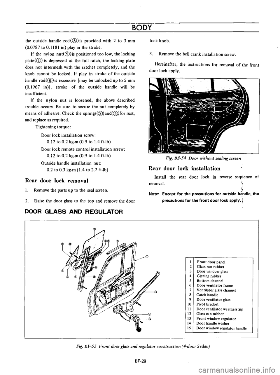
Fig
BF
54
Door
without
sealing
screen
Rear
door
lock
installation
Install
the
rear
door
lock
in
reverse
sequence
of
removal
Note
Except
for
the
precautions
for
outside
handle
the
precautions
for
the
front
door
lock
apply
AD
1
Front
door
panel
2
Glass
run
rubber
3
Door
window
glass
4
Glazing
rubber
5
Bottom
channel
6
Door
ventilator
frame
7
Ventilator
glass
channel
8
Catch
handle
9
Door
ventilator
glass
10
Pivot
bracket
11
Door
ventilator
weatherstrip
12
Glass
run
rubber
13
Front
window
regulator
14
Door
handle
washer
15
Door
window
regulator
handle
Fig
BF
55
Front
door
glass
and
regulator
construction
4
door
Sedan
SF
29
Page 230 of 513
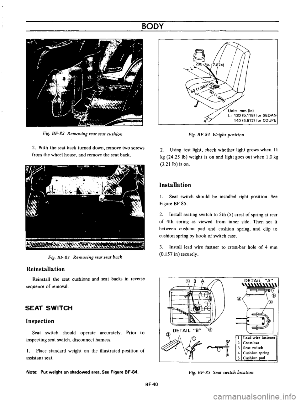
Fig
BF
82
Removing
rear
seat
cushion
2
With
the
seat
back
turned
down
remove
two
screws
from
the
wheel
house
and
remove
the
seat
back
111
I
V
RH
0
1
lr
Fig
BF
83
Removing
rear
seat
back
Reinstallation
Reinstall
the
seat
cushions
and
seat
backs
in
reverse
sequence
of
removal
SEAT
SWITCH
Inspection
Seat
switch
should
operate
accurately
Prior
to
inspecting
seat
switch
disconnect
harness
I
Place
standard
weight
on
the
illustrated
position
of
assistant
seat
Note
Put
weight
on
shadowed
area
See
Figure
BF
84
BODY
Fig
BF
84
Weight
position
Unit
mm
in
L
130
15
118
for
SEDAN
140
5
512
for
COUPE
2
Using
test
light
check
whether
light
grows
when
II
kg
24
25
lb
weight
is
on
and
light
goes
out
when
1
0
kg
3
2
J
lb
is
on
Installation
I
Seat
switch
should
be
installed
right
position
See
Figure
BF
85
2
Install
seating
switch
to
5th
5
crest
of
spring
at
rear
of
4th
spring
as
viewed
from
inner
side
Then
set
it
between
cushion
pad
and
cushion
spring
and
clip
to
cushion
spring
by
hook
of
switch
case
3
Install
lead
wire
fastner
to
cross
bar
hole
of
4
mm
0
157
in
securely
DETAIL
B
@
ui
DETAIL
A
n
@
ID
E
l
1
Lead
wire
fastener
2
Cross
bar
3
Seat
switch
4
Cushion
spring
5
Cushion
pad
Fig
BF
85
Seat
switch
location
BF
40
Page 233 of 513

7
Remmre
three
screws
from
top
of
the
instrument
one
each
installation
bolt
frorn
both
sides
of
the
bottorn
and
two
bolts
used
to
secure
the
instrument
panel
together
with
the
steering
column
clamp
8
Raising
the
instrument
panel
slightly
pull
it
toward
rear
side
of
the
vehicle
and
remove
it
Note
Ensuring
that
all
cables
are
disconnected
remove
the
instrument
panel
slowly
aoo
carefully
REINSTALLATION
Reinstall
the
instrument
panel
in
reverse
sequence
of
removal
BODY
Fig
BF
90
Removing
instrument
panel
II
ROOM
TRIM
INSTALLING
HEAD
LINING
IA
P
AV
FRONT
A
A
IB
A
L
Adhesive
Detailed
view
of
A
portion
B
B
Be
sure
to
hook
the
clamp
securely
Fig
BF
91
Installing
head
lining
Note
Be
sure
to
install
the
roof
insulator
before
installing
the
head
lining
J
BF
43
Page 241 of 513
INSPECTION
Referring
to
the
wiring
diagram
check
the
wiring
harness
for
connection
with
electrical
equipment
and
connector
for
conned
ion
and
installation
When
checking
the
wiring
harness
note
the
following
matters
Connected
unit
should
not
be
loose
rusted
or
contaminated
2
Cable
insulator
cover
should
not
be
damaged
crack
ed
or
insulating
material
should
not
be
deteriorated
3
For
those
parts
which
are
grounded
through
the
installation
bolts
the
bolts
should
be
in
contact
with
the
body
completely
so
that
continuity
is
provided
in
between
the
body
and
bolts
4
Terminals
of
unit
through
which
current
flows
should
not
come
into
contact
with
other
metal
parts
5
No
erroneous
connection
should
be
present
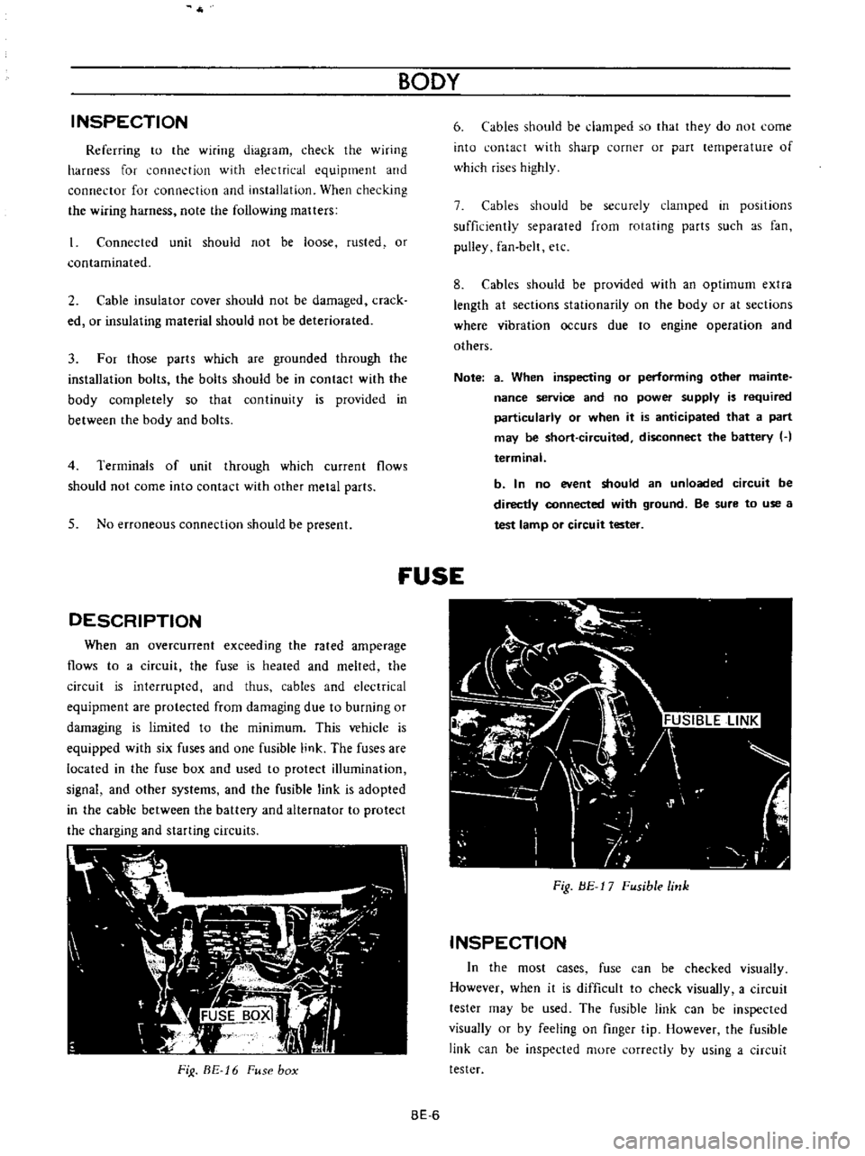
DESCRIPTION
When
an
overcunent
exceeding
the
rated
amperage
flows
to
a
circuit
the
fuse
is
heated
and
melted
the
circuit
is
interrupted
and
thus
cables
and
electrical
equipment
are
protected
from
damaging
due
to
burning
or
damaging
is
limited
to
the
minimum
This
vehicle
is
equipped
with
six
fuses
and
one
fusible
link
The
fuses
are
located
in
the
fuse
box
and
used
to
protect
illumination
signal
and
other
systems
and
the
fusible
link
is
adopted
in
the
cable
between
the
battery
and
alternator
to
protect
the
charging
and
starting
circuits
FiJ
BE
16
Fuse
box
BODY
6
Cables
should
be
damped
so
that
they
do
not
come
into
contact
with
sharp
corner
or
part
lernperature
of
which
rises
highly
7
Cables
should
be
securely
clamped
in
posItions
sufficiently
separated
from
rotating
parts
such
as
fan
pulley
fan
belt
etc
8
Cables
should
be
provided
with
an
optimum
extra
length
at
sections
stationarity
on
the
body
or
at
sections
where
vibration
occurs
due
to
engine
operation
and
others
Note
a
When
inspecting
or
performing
other
mainte
nance
service
and
no
power
supply
is
required
particularly
or
when
it
is
anticipated
that
a
part
may
be
short
circuited
disconnect
the
battery
H
terminal
b
In
no
event
should
an
unloaded
circuit
be
directly
connected
with
ground
Be
sure
to
use
a
test
lamp
or
circuit
tester
fUSE
Fig
BE
17
Fusible
link
INSPECTION
In
the
most
cases
fuse
can
be
checked
visually
However
when
it
is
difficult
to
check
visually
a
circuit
tester
may
be
used
The
fusible
link
can
be
inspected
visually
or
by
feeling
on
finger
tip
However
the
fusible
link
can
be
inspected
more
correctly
by
using
a
circuit
tester
BE
6
Page 251 of 513
9HORN
r
I
01
8ATTERY
HI
IGI
s
ILl
C
iORN
BODY
FUSE
H
S
HORN
BUTTON
BGI
J
H
B
S
Il
I
n6lm
I
L
J
L
HORN
RELAY
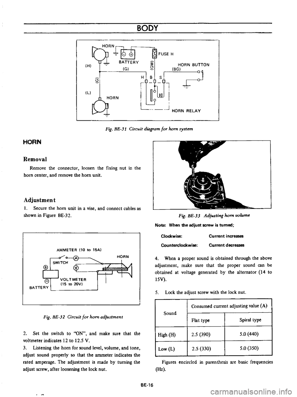
Fig
BE
3l
Circuit
diagram
for
hom
syrtem
HORN
Removal
Remove
the
connector
loosen
the
fixing
nut
in
the
horn
center
and
remove
the
horn
unit
Adjustment
1
Secure
the
horn
unit
in
a
vise
and
connect
cables
as
shown
in
Pigure
BE
32
AMMETER
110
to
15AI
Isw
f
@
113
I
VOLTMETER
I
15
to
20VI
BATTERY
HORN
Fig
BE
32
Circuit
for
ham
adjustment
2
Set
the
switch
to
ON
and
rnake
sure
that
the
voltmeter
indicates
12
to
12
5
V
3
Listening
the
horn
for
sound
level
volurne
and
tone
adjust
sound
properly
so
that
the
amrneter
indicates
the
rated
amperage
The
adjustment
is
made
by
turning
the
adjust
screw
after
loosening
the
lock
nut
Fig
BE
33
Adjusting
hom
IIOlume
Note
When
the
adjust
screw
is
turned
Clockwise
Counterclockwise
Current
increases
Current
decreases
4
When
a
proper
sound
is
obtained
through
the
above
adjustment
rnake
sure
that
the
proper
sound
can
be
obtained
at
voltage
generated
by
the
alternator
14
to
l5V
5
Lock
the
adjust
screw
with
the
lock
nut
Consumed
current
adjusting
value
A
Sound
Plat
type
Spiral
type
High
H
2
5
390
5
0
440
Low
L
2
5
330
5
0
350
Figures
encircled
in
parenthesis
are
basic
frequencies
Hz
BE
16