1973 DATSUN B110 turn signal
[x] Cancel search: turn signalPage 247 of 513
BODY
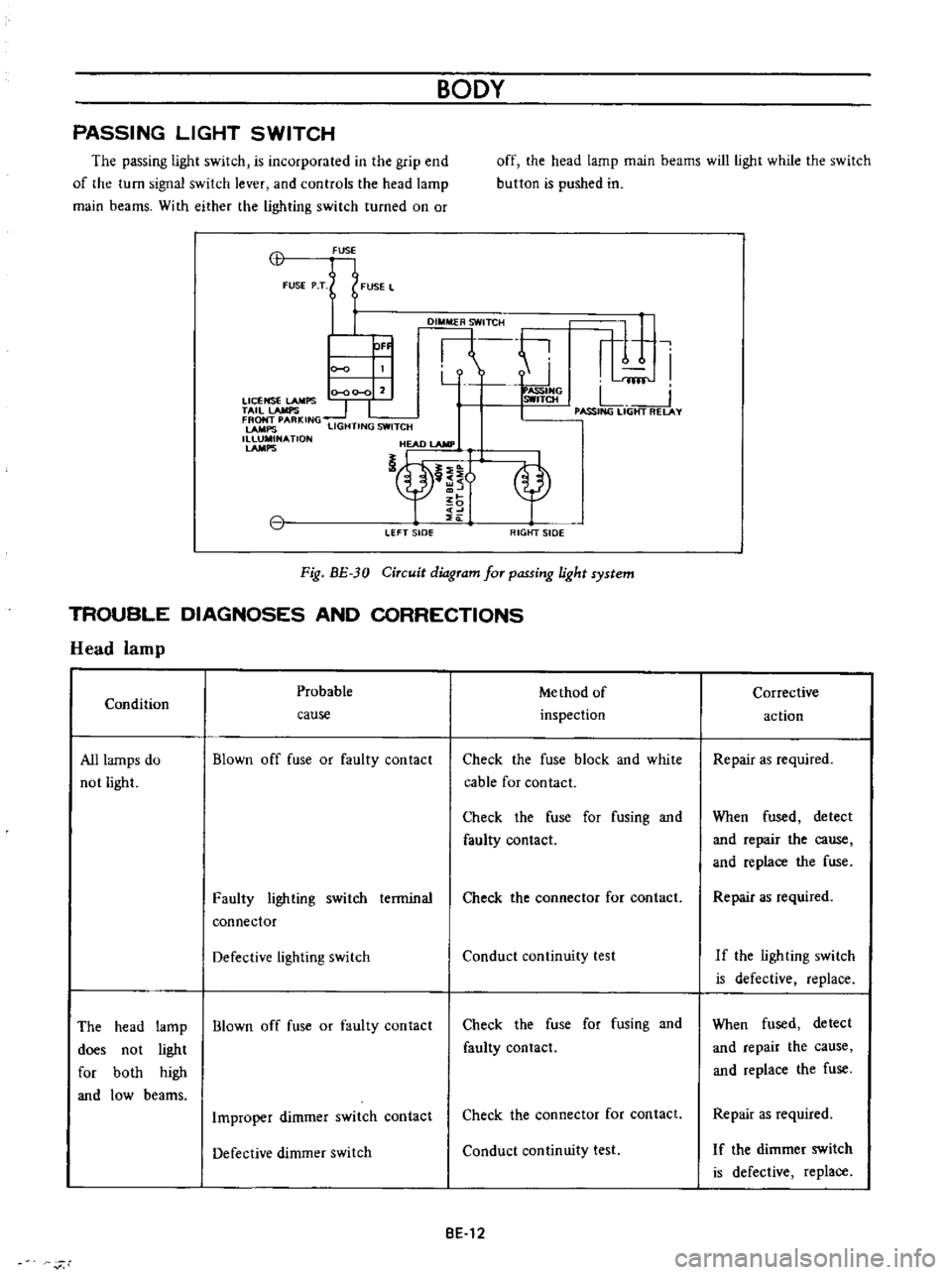
PASSING
LIGHT
SWITCH
The
passing
light
switch
is
incorporated
in
the
grip
end
of
the
turn
signal
switch
lever
and
controls
the
head
lamp
main
beams
With
either
the
lighting
switch
turned
on
or
off
the
head
lamp
main
beams
will
light
while
the
switch
button
is
pushed
in
CB
FUSE
FUSE
P
T
FUSE
L
DI
TCH
ti
r
1
I
Y
fflf
0
00
0
2
ASSIHG
LICENSE
LAMPS
SWITCH
L
TAil
lAMPS
1
I
I
PASSING
LIGHT
RELAY
FRONT
PARKING
LAMPS
LIGHTING
SWITCH
1
NATlON
HEAD
lAMP
nt
OF
LEFT
sIDe
RIGtfT
SIDE
Fig
BE
30
Circuit
diagram
for
passing
light
system
TROUBLE
DIAGNOSES
AND
CORRECTIONS
Head
lamp
Probable
Me
thod
of
Condition
inspection
cause
All
lamps
do
not
light
Blown
off
fuse
or
faulty
contact
Check
the
fuse
block
and
white
cable
for
contact
Check
the
fuse
for
fusing
and
faulty
contact
Faulty
lighting
switch
terminal
connector
Check
the
connector
for
contact
Defective
lighting
switch
Conduct
continuity
test
The
head
lamp
Blown
off
fuse
or
faulty
contact
does
not
light
for
both
high
and
low
beams
Check
the
fuse
for
fusing
and
faulty
contact
Improper
dimmer
switch
contact
Check
the
connector
for
contact
Defective
dimmer
switch
Conduct
continuity
test
BE
12
r
Corrective
action
Repair
as
required
When
fused
detect
and
repair
the
cause
and
replace
the
fuse
Repair
as
required
If
the
ligh
ting
swi
tch
is
defective
replace
When
fused
detect
and
repair
the
cause
and
replace
the
fuse
Repair
as
required
I
f
the
dimmer
switch
is
defective
replace
Page 248 of 513
BODY
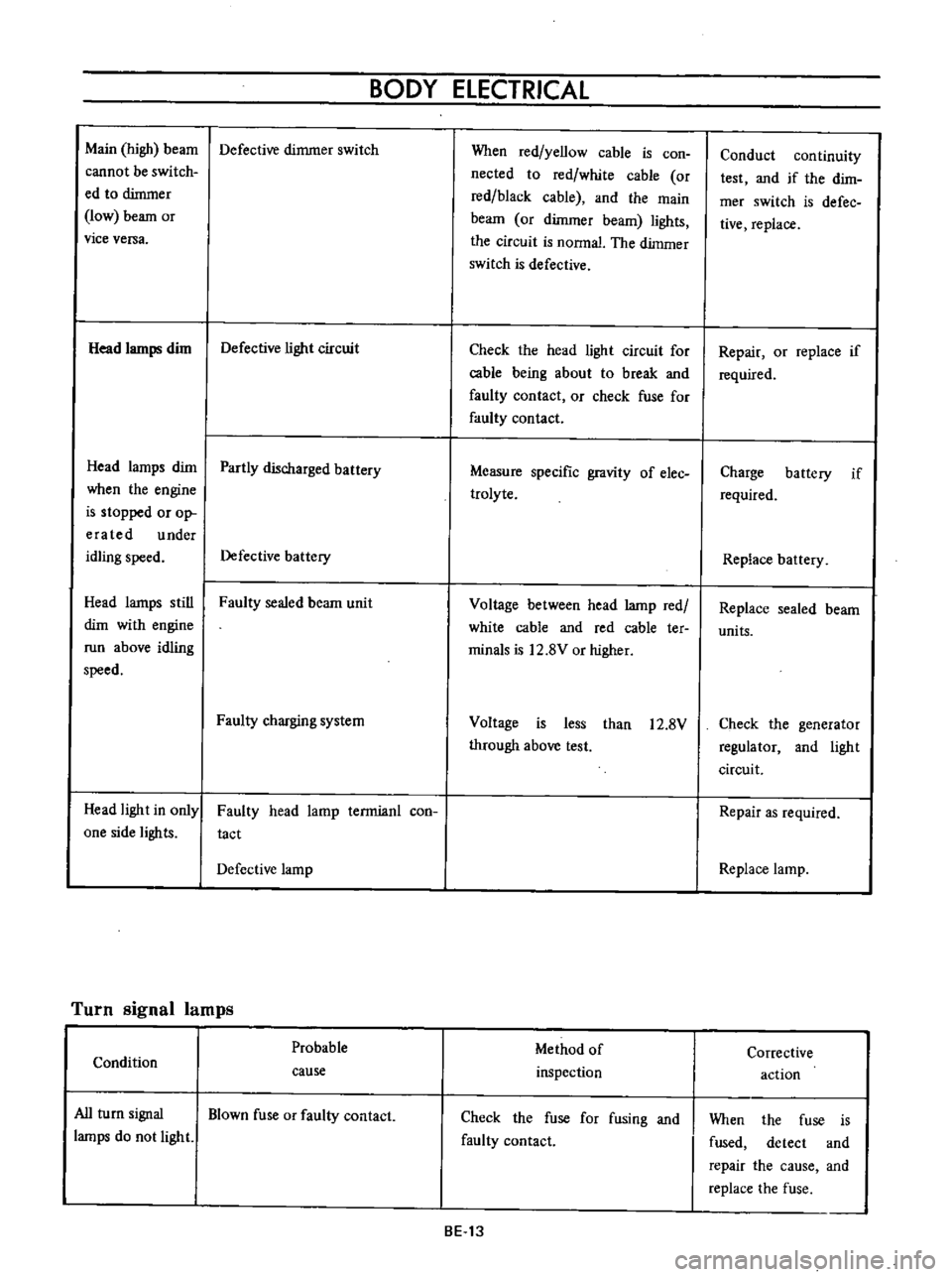
ELECTRICAL
Main
high
beam
Defective
dimmer
switch
cannot
be
switch
ed
to
dimmer
low
beam
or
vice
versa
Head
lamps
dim
Defective
light
circuit
Head
lamps
dim
Partly
discharged
battery
when
the
engine
is
stopped
or
op
era
ted
under
idling
speed
Defective
battery
Head
lamps
still
Faulty
sealed
beam
unit
dim
with
engine
run
above
idling
speed
Faulty
charging
system
Head
light
in
only
one
side
lights
Faulty
head
lamp
terrnianl
con
tact
Defective
lamp
Turn
signal
lamps
Probable
Condition
cause
All
turn
signal
Blown
fuse
or
faulty
contact
lamps
do
not
light
When
red
yellow
cable
is
con
nected
to
red
white
cable
or
red
black
cable
and
the
main
beam
or
dimmer
beam
lights
the
circuit
is
nonnal
The
dimmer
switch
is
defective
Check
the
head
light
circuit
for
cable
being
about
to
break
and
faulty
contact
or
check
fuse
for
faulty
contact
Measure
specific
gravity
of
elec
trolyte
Voltage
between
head
lamp
red
white
cable
and
red
cable
ter
minals
is
12
8V
or
higher
Voltage
is
less
than
12
8V
through
above
test
Method
of
inspection
Check
the
fuse
for
fusing
and
faulty
contact
BE
13
Conduct
continuity
test
and
if
the
dirn
mer
switch
is
defec
tive
replace
Repair
or
replace
if
required
Charge
battery
if
required
Replace
battery
Replace
sealed
beam
units
Check
the
generator
regulator
and
light
circuit
Repair
as
required
Replace
lamp
Corrective
action
When
the
fuse
is
fused
detect
and
repair
the
cause
and
replace
the
fuse
Page 249 of 513
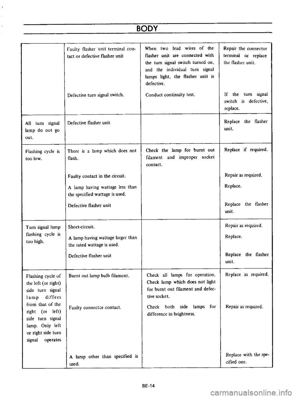
All
turn
signal
lamp
do
not
go
out
Flashing
cycle
is
too
low
Turn
signal
lamp
flashing
cycle
is
too
high
Flashing
cycle
of
the
left
or
right
side
turn
signal
lamp
differs
from
that
of
the
right
or
left
side
turn
signal
lamp
Only
left
or
right
side
turn
signal
operates
Faulty
flasher
unit
terminal
con
tact
or
defective
flasher
unit
Defective
turn
signal
switch
Defective
flasher
unit
There
is
a
lam
p
which
does
no
t
flash
Faulty
contact
in
the
circuit
A
lamp
having
wattage
less
than
the
specified
wattage
is
used
Defective
flasher
unit
Short
ircuit
A
lamp
having
wattage
larger
than
the
rated
wattage
is
used
Defective
flasher
unit
Burnt
out
lamp
bulb
filament
Faulty
connect
contact
A
lamp
other
than
specified
is
used
BODY
When
two
lead
wires
of
the
flasher
unit
are
connected
with
the
turn
signal
switch
turned
on
and
the
individual
turn
signal
larnps
light
the
flasher
unit
is
defective
Conduct
continuity
test
Check
the
lamp
for
burnt
out
filament
and
improper
socket
contact
Check
all
lamps
for
operation
Check
lamp
which
does
not
light
for
burnt
out
filarnent
and
defec
tive
socket
Check
both
side
larnps
for
difference
in
brightness
BE
14
Repair
the
connector
terminal
or
replace
the
flasher
unit
If
the
turn
signal
switch
is
defective
replace
Replace
the
flasher
Wlit
Replace
if
required
Repair
as
required
Replace
Replace
the
flasher
writ
Repair
as
required
Replace
Replace
the
flasher
unit
Replace
as
required
Repair
as
required
Replace
with
the
spe
cified
one
Page 256 of 513

BODY
ElECTRICAL
When
the
ignition
switch
is
set
to
ON
the
ignition
wa
rning
circuit
is
closed
and
current
flows
flows
from
the
ignition
switch
to
the
warning
lamp
bulb
and
ground
through
the
regulator
When
the
engine
is
started
and
the
generator
comes
into
operation
the
generator
output
current
opposes
the
current
flowing
from
the
warning
lamp
in
effect
it
breaks
the
warning
circuit
ground
connection
and
the
lamp
goes
out
l
r
hffi
u
z
Ignition
switch
I
Q
6
I
0
c
M
1
E
8
ca
i
L
g
PI
lot
c
P
I
j
co
rt
0
relay
E
0
5
y
y
1
N
N
3
Alternator
Regulator
Fig
BE
41
Circuit
of
ignition
warning
system
HAND
BRAKE
WARNING
LAMP
This
lamp
functions
both
hand
brake
warning
larnp
and
BULB
SPECIFICATIONS
service
brake
line
pressure
differential
warning
lamp
When
a
difference
between
front
and
rear
brake
line
pressures
reaches
the
rated
range
13
to
17
kgfcm2
185
to
242
lb
sq
in
the
ground
circuit
for
the
warning
lamp
is
closed
and
the
warning
lamp
lights
IGNITION
SWITCH
WARNING
LAMP
L
E
WARNING
SWITCH
1
SERVICE
BRAKE
LINE
PRESSU
R
E
DIFFERENTIAL
WARNING
J
SWITCH
Fig
BE
42
Circuit
diagram
for
brake
warning
system
tern
Specifications
Square
type
meter
Round
type
meter
Meter
illumination
larnp
VoW
12
3
4
2
12
1
7
3
Turn
signal
pilot
lamp
VoW
12
3
4
2
12
1
7
2
Head
lamp
main
high
beam
VoW
12
3
4
I
12
17
1
pilot
lamp
Ignition
warning
lamp
VoW
123
4
I
12
17
1
Oil
pressure
warning
lamp
VoW
12
3
4
1
12
1
7
1
Hand
brake
warning
lamp
VoW
12
1
7
1
for
U
S
A
CANADA
Clock
illumination
lamp
VoW
123
4
I
12
17
2
Figure
encircled
in
parentheses
indicates
number
of
bulbs
used
BE
21
Page 268 of 513
BODY
ELECTRICAL
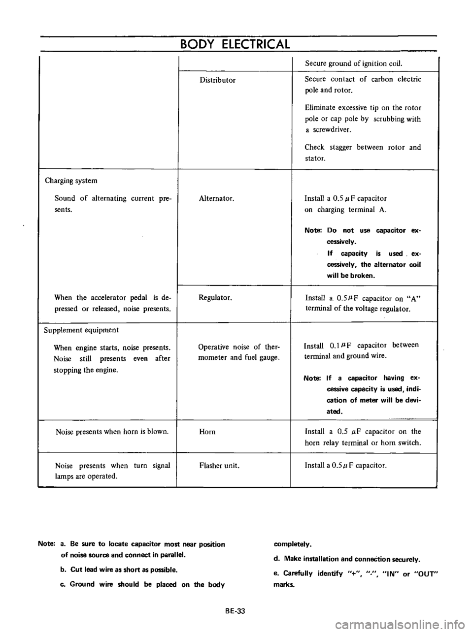
Distributor
Secure
ground
of
ignition
coil
Secure
contact
of
carbon
electric
pole
and
rotor
Eliminate
excessive
tip
on
the
rotor
pole
or
cap
pole
by
scrubbing
with
a
screwdriver
Check
stagger
between
rotor
and
stator
Charging
system
Sound
of
alternating
current
pre
sents
Alternator
Install
a
0
5
l
F
capacitor
on
charging
terminal
A
Note
Do
not
use
capacitor
ex
cessively
If
capacity
is
used
ex
cessively
the
alternator
coil
will
be
broken
When
the
accelerator
pedal
is
de
pressed
or
released
noise
presents
Regulator
Install
a
0
5
l
F
capacitor
on
A
terrninal
of
the
voltage
regulator
Supplement
equipment
When
engine
starts
noise
presents
Noise
still
presents
even
after
stopping
the
engine
Operative
noise
of
ther
rnometer
and
fuel
gauge
Install
0
1
l
F
capacitor
between
terminal
and
ground
wire
Note
If
a
capacitor
having
ex
cessive
capacity
is
used
indi
cation
of
meter
will
be
devi
ated
Noise
presents
when
horn
is
blown
Horn
Install
a
0
5
IF
capacitor
on
the
horn
relay
terminal
or
horn
switch
Noise
presents
when
turn
signal
lamps
are
operated
Flasher
unit
Install
a
0
5
l
F
capacitor
Note
a
Be
sure
to
locate
capacitor
most
near
position
of
noise
source
and
connect
in
parallel
completely
d
Make
installation
and
conneCtion
securely
b
Cut
lead
wire
as
short
as
possible
c
Ground
wire
should
be
placed
on
the
body
e
Carefully
identify
marks
IN
or
OUT
BE
33
Page 318 of 513
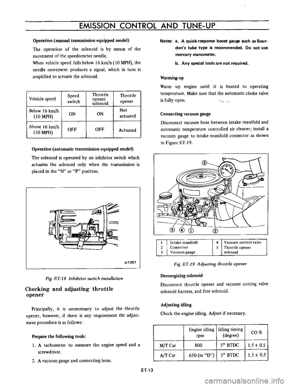
EMISSION
CONTROL
AND
TUNE
UP
Operation
manual
transmission
equipped
model
The
operation
of
the
solenoid
is
by
means
of
the
movement
of
the
speedometer
needle
When
vehicle
speed
falls
below
16
km
h
10
MPH
the
needle
movement
produces
a
signal
which
in
turn
is
amplified
to
actuate
the
solenoid
I
Vehicle
speed
Speed
Throttle
Throttle
switch
opener
opener
solenoid
Below
16
km
h
Not
10
MPH
ON
ON
actuated
Above
16
km
h
OFF
OFF
Actuated
10
MPH
Operation
automatic
transmission
equipped
model
The
solenoid
is
operated
by
an
inhibitor
switch
which
actuates
the
solenoid
only
when
the
transmission
is
placed
in
the
N
or
P
position
c
fil
rn
AT057
Fig
ET
18
Inhibitor
switch
installation
Checking
and
adjusting
throttle
opener
Principally
it
is
unnecessary
to
adjust
the
throttle
opener
however
if
there
is
any
requirement
the
adjust
ment
procedure
is
as
follows
Prepare
the
following
tools
1
A
tachometer
to
measure
the
engine
speed
and
a
screwdriver
2
A
vacuum
gauge
and
connecting
hose
ET
13
Notes
a
A
quick
response
boost
gauge
such
as
Bour
don
s
tube
type
is
recommended
Do
not
use
mercury
manometer
b
Any
special
tools
are
not
required
Warming
up
Warm
up
engine
until
it
is
heated
to
operating
temperature
Make
sure
that
the
automatic
choke
valve
is
fully
open
Connecting
vacuum
gauge
Disconnect
vacuum
hose
between
intake
manifold
and
automatic
temperature
controlled
air
cleaner
install
a
vacuum
gauge
to
intake
manifold
connector
as
shown
in
Figure
ET
19
1
Intake
manifold
2
Connector
3
Vacuum
gauge
4
Vacuum
control
valve
5
Throttle
opener
solenoid
Fig
ET
19
Adjusting
throttle
opener
Deenergizing
solenoid
Disconnect
throttle
opener
and
vacuum
cutting
valve
solenoid
harness
and
free
solenoid
Adjusting
idling
Check
the
engine
idling
Adjust
if
necessary
Engine
idling
rpm
Idling
timing
I
CO
degree
SO
BTDC
I
L51c0
5
SO
BTDC
I
I
S
1c
0
5
M
T
Car
A
TCar
800
6S0
in
D
Page 504 of 513

TRANSMISSION
COLUMN
SHIFT
CONTROL
SYSTEM
Removal
Remove
the
steering
wheel
assembly
Fig
TM
54
Rem01
ing
steering
wheel
2
Remove
the
steering
column
shell
cover
turn
signal
and
lighting
switch
completely
Fig
TM
55
Removing
steering
column
shell
cover
Fig
TM
56
Removing
turn
signal
and
lighting
switch
3
Remove
the
snap
ring
and
control
lever
pivot
pin
and
withdraw
the
hand
lever
A
A
V
l
Y
e
f
I
1
I
V
e
tl
f
r
4
2i
L
1
I
Snap
ring
2
Control
lever
pivot
pin
I
3
I
C
washer
Fig
TM
57
Withdrawing
hand
ever
4
Remove
the
C
washer
TM
17
i
MI
ig
r
M
5J
emOVing
change
lever
J
y
Ji
1
r
oJ