1973 DATSUN B110 turn signal
[x] Cancel search: turn signalPage 7 of 513

AUTOMATIC
TRANSMISSION
Manual
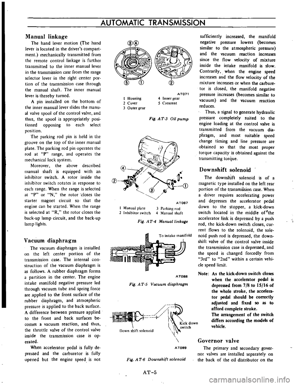
linkage
The
hand
lever
motion
The
hand
lever
is
located
in
the
driver
s
com
part
men
mechanically
transmitted
from
the
remote
control
linkage
is
further
transmitted
to
the
inner
manual
lever
in
the
transmission
case
from
the
range
selector
lever
in
the
right
center
poc
tion
of
the
transmission
case
through
the
manual
shaft
The
inner
manual
lever
is
thereby
turned
A
pin
installed
on
the
bottom
of
the
inner
manual
lever
slides
the
manu
al
valve
spool
of
the
control
valve
and
thus
the
spool
is
appropriately
posi
lioned
opposing
to
each
select
position
The
parking
rod
pin
is
held
in
the
groove
on
the
top
of
the
inner
manual
plate
The
parking
rod
pin
operates
the
rod
at
p
range
and
operates
the
mechanical
lock
system
Moreover
the
above
described
manual
shaft
is
equipped
with
an
inhibitor
switch
A
rotor
inside
the
inhibitor
switch
rotates
in
response
to
each
range
When
the
range
is
selected
at
p
or
N
the
rotor
closes
the
starter
magnet
circuit
so
that
the
engine
can
be
started
When
the
range
is
selected
at
R
the
rotor
closes
the
back
up
lamp
circuit
and
the
back
up
lamp
lights
Vacuum
diaphragm
The
vacuum
diaphragm
is
installed
un
the
left
center
portion
of
the
transmission
case
The
internal
con
struction
of
the
vacuum
diaphragm
is
as
follows
A
rubber
diaphragm
forms
a
partition
in
the
center
The
engine
intake
manifold
negative
pressure
led
through
vacuum
tube
and
spring
force
are
applied
to
the
front
surface
of
the
rubber
diaphragm
and
atmospheric
pressure
is
applied
to
the
back
surface
A
difference
between
pressure
applied
to
the
front
and
back
surfaces
be
comes
a
vacuum
reaction
and
thus
the
throttle
valve
of
the
control
valve
inside
the
transmission
case
is
op
erated
When
accelerator
pedal
is
fully
de
pressed
and
the
carburetor
is
fully
upened
but
the
engine
speed
is
not
1
Housing
2
Cover
3
Outer
gear
AT071
4
Inner
gear
5
Crescent
Fig
AT
3
Oil
pump
1
Manual
plate
2
Inhibitor
switch
A
TOB7
3
Parking
rod
4
Manual
shaft
Fig
AT
4
Manuallinhage
To
intake
manifold
A
TOBB
Fig
A
T
5
Vacuum
diaphragm
iV
Down
shift
solenoid
i
KiCk
down
switch
A
TOB9
Fig
A
T
6
Downshift
solenoid
AT
5
sufficiently
increased
the
manifold
negative
pressure
lowers
becomes
similar
to
the
atmospheric
pressure
and
the
vacuum
reaction
increases
since
the
flow
velocity
of
mixture
inside
the
intake
manifold
is
slow
Contrarily
when
the
engine
speed
increases
and
the
flow
velocity
of
the
mixture
increases
or
when
the
carbure
tor
is
closed
the
manifold
negative
pressure
increases
becomes
similar
to
vacuum
and
the
vacuum
reaction
reduces
Thus
a
signal
to
generate
hydraulic
pressure
completely
suited
to
the
engine
loading
at
the
control
valve
is
transmitted
from
the
vacuum
dia
phragm
and
most
suitable
speed
change
timing
and
line
pressure
are
obtained
so
that
the
most
proper
torque
capacity
is
obtained
against
the
transmitting
torque
Downshift
solenoid
The
downshift
solenoid
is
of
a
magnetic
type
installed
on
the
left
rear
portion
of
the
transmiSsion
case
When
a
driver
requires
accelerating
power
and
depresses
the
accelerator
pedal
down
to
the
stopper
a
kick
down
switch
located
in
the
middle
of
the
accelerator
link
is
depressed
by
a
push
rod
the
kick
down
switch
closes
cur
rent
flows
to
the
solenoid
the
sole
noid
push
rod
is
depressed
the
down
shift
valve
of
the
control
valve
inside
the
transmission
case
is
depressed
and
the
speed
is
changed
forcedly
from
3rd
to
2nd
within
a
certain
vehi
cle
speed
limit
Note
As
the
kick
own
switch
closes
when
the
accelerator
pedal
is
depressed
from
7
8
to
IS
16
of
the
whole
stroke
the
accelera
tor
pedal
should
be
correctly
adjusted
and
fixed
so
as
to
afford
complete
stroke
The
arrangement
of
the
switch
differs
according
the
models
of
vehicle
Governor
valve
The
primary
and
secondary
gover
nor
valves
are
installed
separately
on
the
back
of
the
oil
distributor
on
the
Page 113 of 513

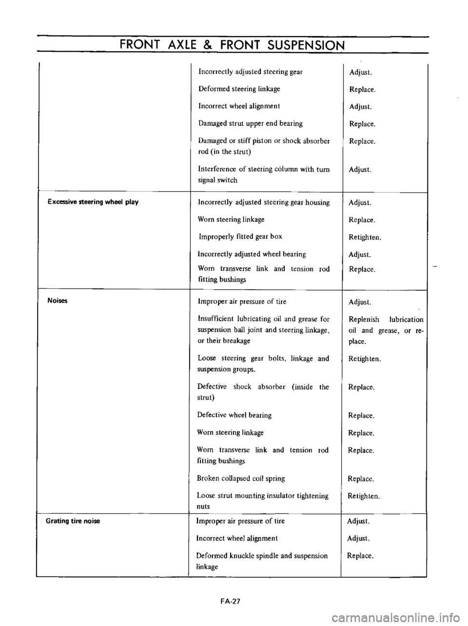
FRONT
AXLE
FRONT
SUSPENSION
Incorrectly
adjusted
steering
gear
Deformed
steering
linkage
Incorrect
wheel
alignment
Damaged
strut
upper
end
bearing
Damaged
or
stiff
piston
or
shock
absorber
rod
in
the
strut
Interference
of
steering
column
with
turn
signal
switch
Excessive
steering
wheel
play
Noises
Grating
tire
noise
Incorrectly
adjusted
steering
gear
housing
Worn
steering
linkage
Improperly
fitted
gear
box
Incorrectly
adjusted
wheel
bearing
Worn
transverse
link
and
tension
rod
fitting
bushings
Improper
air
pressure
of
tire
Insufficient
lubricating
oil
and
grease
for
suspension
ball
joint
and
steering
linkage
or
their
breakage
Loose
steering
gear
bolts
linkage
and
suspension
groups
Defective
shock
absorber
inside
the
strut
Defective
wheel
bearing
Worn
steering
linkage
Worn
transverse
link
and
tension
rod
fitting
bushings
Broken
collapsed
coil
spring
Loose
strut
mounting
insulator
tightening
nuts
Improper
air
pressure
of
tire
Incorrect
wheel
alignment
Deformed
knuckle
spindle
and
suspension
linkage
FA
27
Adjust
Replace
Adjust
Replace
Replace
Adjust
Adjust
Replace
Retighlen
Adjust
Replace
Adjust
Replenish
lubrication
oil
and
grease
or
re
place
Retighten
Replace
Replace
Replace
Replace
Replace
Retighten
Adjust
Adjust
Replace
Page 162 of 513

Iii
I
o
t
I
I
CHASSIS
Fig
ST
2
Steering
wheel
REMOVAL
1
Remove
the
horn
ring
and
remove
the
steering
wheel
nut
and
pull
out
the
steering
wheel
by
the
use
of
a
Steer
ing
wheel
puller
ST27180000
3
Remove
the
turn
signal
and
lighting
switch
com
pletely
4
Remove
the
hand
lever
assembly
from
the
control
rod
assembly
by
unscrewing
the
fIxing
bolts
5
Remove
two
fIxing
bolts
used
to
secure
the
steering
column
to
the
instrument
panel
ST27180000
Fig
ST
3
Removing
steering
wheel
lock
nut
Note
The
horn
ring
can
be
easily
removed
by
two
bolts
2
Remove
the
steering
column
shell
Fig
ST
4
Removing
steering
column
upper
side
ST
2
Page 232 of 513

BODY
INSTRUMENT
PANEL
CONTENTS
REMOVAL
BF
42
REMOVAL
Fig
BF
88
Removing
instrument
panel
Note
There
are
two
types
of
instrument
panel
square
type
and
round
type
However
both
of
them
are
removed
and
reinstalled
in
the
same
manner
Disconnect
the
battery
cable
at
the
battery
terminal
2
Disconnect
the
wiring
harness
connector
units
Disconnect
the
instrument
harness
from
the
engine
compartment
harness
Disconnect
the
instrument
harness
from
the
turn
signal
switch
Disconnect
the
instrument
harness
frorn
the
body
harness
Disconnect
the
instrumen
t
harness
connected
to
the
door
switch
stop
lamp
switch
flasher
unit
and
passing
light
relay
option
REINSTALLATION
BF
43
Note
When
disconnecting
the
wiring
harness
recom
mend
to
use
tags
for
identifying
their
relationship
3
Disconnect
cables
for
radio
antenna
and
speaker
4
Remove
the
package
tray
the
shell
cover
and
turn
signal
switch
Note
Work
may
be
carried
out
without
removing
die
steering
wheel
However
it
is
recommended
to
remove
the
steering
wheel
50
that
work
can
be
carried
out
more
easily
5
Disconnect
the
speedometer
cable
from
the
speedometer
unit
6
Disconnect
the
heater
control
cable
at
the
heater
side
Fig
BF
89
Removing
imtrument
panel
Ii
BF
42
Page 242 of 513

BODY
ELECTRICAL
Note
8
When
a
fuse
is
blown
off
be
sure
to
correct
the
cause
before
installing
new
fuse
b
Be
sure
to
use
fuse
having
the
rated
capacity
Do
not
use
fuse
having
larger
capacity
i
e
20A
JOA
etc
c
Particularly
when
the
fusible
link
is
fused
replace
with
a
designated
fusible
link
Green
color
link
for
model
8110
In
comparison
with
fuse
much
higher
current
flows
through
the
fusible
link
Moreover
it
is
important
to
eliminate
the
cause
of
blown
off
fusible
link
before
replacing
d
When
fuse
is
connected
incorrectly
and
the
contact
is
loose
voltage
drops
and
heat
are
gener
ated
resulting
abnormally
operated
electrical
equip
ment
Remove
dust
or
when
oxidized
polish
with
a
fine
emery
paper
so
that
the
contact
is
improved
LlGHTING
SYSTEM
CONTENTS
HEAD
LAMP
Descri
ption
Sealed
beam
replacement
Aiming
adjustment
FRONT
PARKING
AND
TURN
SIGNAL
SIDE
FLASHER
IMARKER
LAMP
AN
D
LICENSE
LAMP
REAR
COMBINATION
LAMPS
BULB
SPECIFICATIONS
TURN
SIGNAL
AND
DIMMER
COMBINATION
SWITCH
BE
7
BE
7
BE
7
BE
8
LAMP
BE
8
BE
9
BE10
BE10
HEAD
LAMP
Description
All
weather
type
sealed
beam
2
light
system
front
lamps
are
adopted
Each
lamp
of
both
side
head
lamps
is
provided
with
high
beam
filament
for
long
range
SOW
and
low
beam
filarnent
for
dipping
40W
In
other
words
the
lamp
is
of
a
double
filament
type
Sealed
beam
replacement
I
Rernove
the
wiring
socket
from
back
of
the
head
lamp
2
Remove
the
screws
attaching
the
front
grille
to
the
radiator
core
support
Coupe
only
Remove
three
retaining
screws
and
remove
the
head
lamp
rim
All
other
than
coupe
3
Loosen
three
screws
used
to
install
the
retaining
ring
on
the
sealed
bearn
mounting
ring
and
remove
the
sealed
Removal
LIGHTING
SWITCH
Removal
HAZARD
WARNING
SWITCH
PASSING
LIGHT
SWITCH
TROUBLE
DIAGNOSES
AND
CORRECTIONS
Head
lamp
Turn
signal
lamps
Tail
and
stop
lamp
license
lamp
back
up
lamp
BE
10
BE
11
BE
11
BE
11
BE
12
BE
12
BE
12
BE
13
BE
15
i
Ii
beam
unit
4
When
installing
a
new
unit
be
sure
to
position
the
Top
mark
to
the
top
of
ring
1
2
Sealed
beam
unit
Sealed
beam
mounting
ring
3
Retaining
ring
4
Aiming
adjusting
screws
Fig
BE
18
Replacing
sealed
beam
BE
7
Page 243 of 513

n
YR
f
f1
JC
1
r
8bD
l
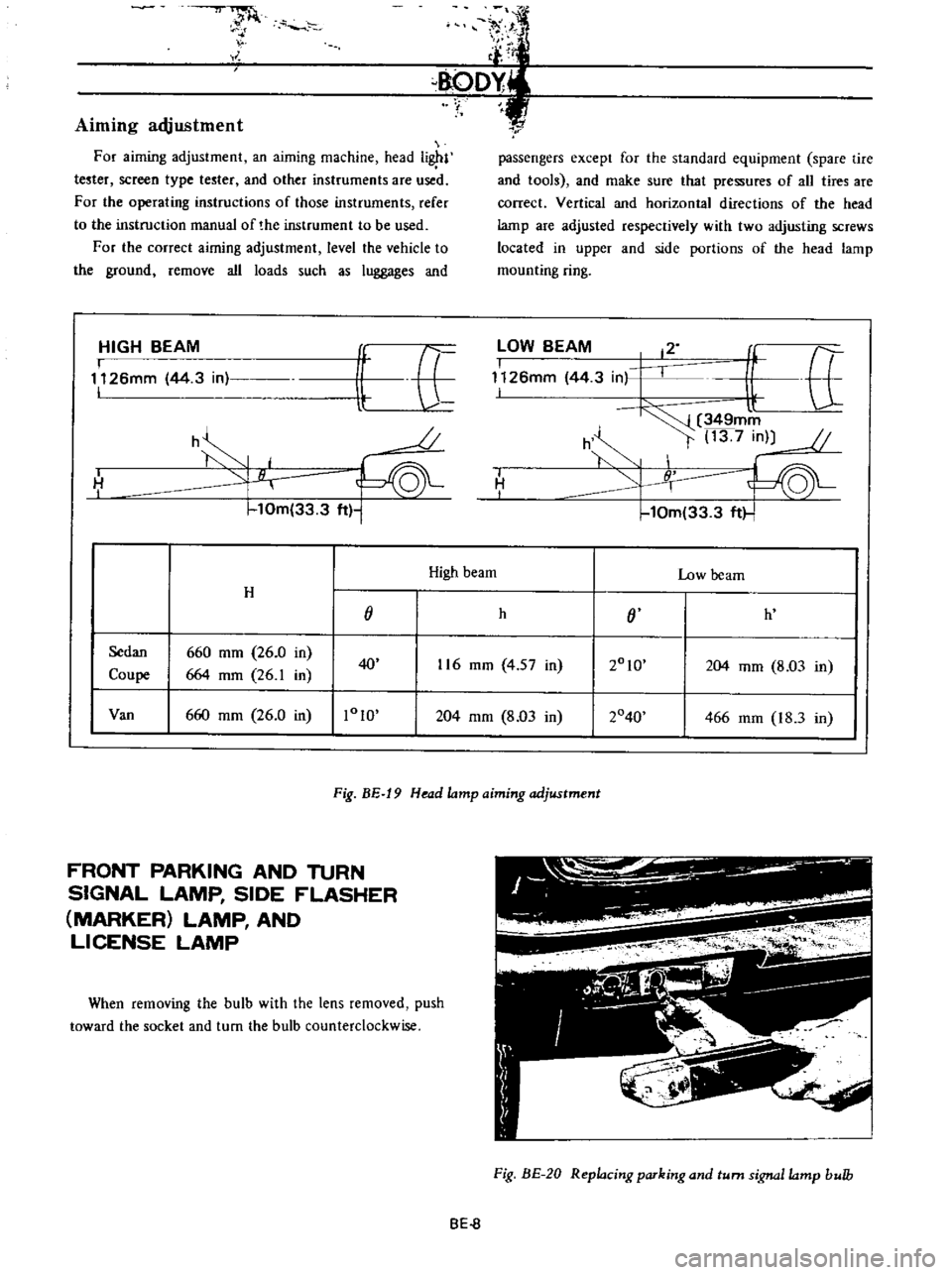
Aiming
adjustment
For
aiming
adjustment
an
aiming
machine
head
i
l
tester
screen
type
tester
and
other
instruments
are
used
For
the
operating
instructions
of
those
instruments
refer
to
the
instruction
manual
of
the
instrument
to
be
used
For
the
correct
airning
adjustment
level
the
vehicle
to
the
ground
remove
all
loads
such
as
luggages
and
HIGH
BEAM
I
1126mm
44
3
in
I
it
E
U
o
h
H
I
10m
33
3
ft
1
r
passengers
except
for
the
standard
equipment
spare
tire
and
tools
and
make
sure
that
pressures
of
all
tires
are
correct
Vertical
and
horizontal
directions
of
the
head
lamp
are
adjusted
respectively
with
two
adjusting
screws
located
in
upper
and
side
portions
of
the
head
lamp
mounting
ring
lOW
BEAM
12
I
f
tt
1126mm
44
3
in
I
l
349mm
h
t
13
7
in
10m
33
3
ft
I
H
I
High
beam
Low
beam
H
j
h
j
h
Sedan
660
mm
26
0
in
2010
Coupe
664
mm
26
1
in
40
116
mm
4
57
in
204
mm
8
03
in
Van
660
mm
26
0
in
1010
204
mm
8
03
in
2040
466
mm
18
3
in
Fig
BE
19
Head
lamp
aiming
adjustment
FRONT
PARKING
AND
TURN
SIGNAL
LAMP
SIDE
FLASHER
MARKER
LAMP
AND
LICENSE
LAMP
When
removing
the
bulb
with
the
lens
removed
push
toward
the
socket
and
turn
the
bulb
counterclockwise
Fig
BE
20
Replacing
parking
and
turn
signa
lamp
bulb
BE
8
Page 245 of 513

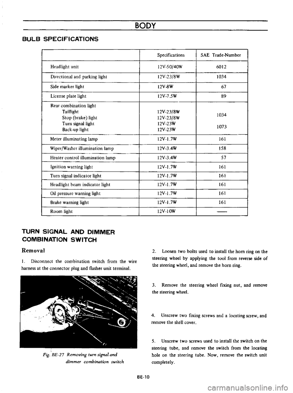
BULB
SPECIFICATIONS
Headlight
unit
Directional
and
parking
light
Side
marker
light
License
plate
light
Rear
combination
light
Taillight
Stop
brake
light
Turn
signal
light
Back
up
light
Meter
illuminating
lamp
Wiper
Washer
illumination
lamp
Heater
control
illumination
lamp
Ignition
warning
light
Turn
signal
indicator
light
Headlight
beam
indicator
light
Oil
pressure
warning
light
Brake
warning
ligh
t
Room
light
TURN
SIGNAL
AND
DIMMER
COMBINATION
SWITCH
Removal
Disconnect
the
combination
switch
from
the
wire
harness
at
the
connector
plug
and
flasher
unit
terrninal
Fig
BE
27
Removing
turn
signal
and
dimmer
combination
switch
BODY
Specifications
SAE
Trade
Number
12V
SO
40W
6012
12V
23
8W
1034
12V
8W
67
l2V
7
5W
89
12V
23
8W
1034
l2V
23
8W
l2V
23W
1073
l2V
23W
12V
I
7W
161
l2V
3
4W
158
l2V
3
4W
57
l2V
17W
161
l2V
17W
161
l2V
17W
161
l2V
17W
161
l2V
17W
161
l2V
IOW
2
Loosen
two
bolts
used
to
install
the
horn
ring
on
the
steering
wheel
by
applying
the
tool
from
reverse
side
of
the
steering
wheel
and
remove
the
horn
ring
3
Remove
the
steering
wheel
fixing
nut
and
remove
the
steering
wheel
4
Unscrew
two
fixing
screws
and
a
locating
screw
and
remove
the
shell
cover
5
Unscrew
two
screws
used
to
install
the
switch
on
the
steering
tube
and
remove
the
switch
from
the
locating
hole
on
the
steering
tube
Now
remove
the
switch
unit
completely
BE
10
Page 246 of 513

BODY
ELECTRICAL
8
G
J
r
ICENSE
LAMPS
10
0
I
I
g
N
Ap
KING
10
00
01
2
I
NATION
J
J
r
j
a
iii
a
g
Lv
F
a
G
G
Lo
o
0
I
I
m
L
J
HER
UNIT
DIMMER
SWITCH
TURN
SIONAl
SWITCH
I
I
Fig
BE
28
Circuit
diagram
for
turn
signal
and
dimmer
switch
system
LIGHTING
SWITCH
HAZARD
WARNING
SWITCH
Removal
The
hazard
lamp
system
4
way
flasher
consists
of
hazard
warning
switch
and
flasher
unit
When
the
hazard
warning
switch
is
turned
on
all
signal
lamps
flash
simultaneously
telling
other
drivers
that
the
vehicle
is
stopped
When
the
turn
signal
lamps
flash
the
pilot
lamps
on
the
instrument
panel
also
flash
telling
you
of
hazard
lamp
operation
1
Rernove
the
connector
from
back
of
the
lighting
switch
2
Depressing
the
lighting
switch
knob
turn
it
counter
clockwise
and
remove
it
3
Loosen
the
escutcheon
switch
frorn
the
cluster
lid
and
remove
the
lighting
IGNITION
SWITCH
EZ
L
I
U
I
JJ
u
HAZARD
UNIT
Ip
FLASHER
UNIT
HAZARD
WARNING
SWITCH
161
6
6
g
Q
a
ll
Zll
Zll
CE
O
a
We
a
l
e
rY
1
LEFT
SiDE
RIGHT
SIDE
Fig
BE
29
Circuit
diagram
for
hazard
lamp
system
BE
11