1973 DATSUN B110 cooling
[x] Cancel search: coolingPage 308 of 513
EMISSION
CONTROL
AND
TUNE
UP
Capacity
Maximum
3
3
L
X
US
gal
y
Imp
gal
2
3
L
US
gal
f
Imp
gal
Minimum
Make
sure
that
engine
oil
is
not
deteriorated
with
cooling
water
or
gasoline
Drain
and
refill
the
oil
if
necessary
Notes
a
A
milky
oil
indicates
the
presence
of
cooling
water
Find
the
cause
for
necessary
corrective
action
b
Oil
with
extremely
low
viscosity
indicates
dilution
with
gasoline
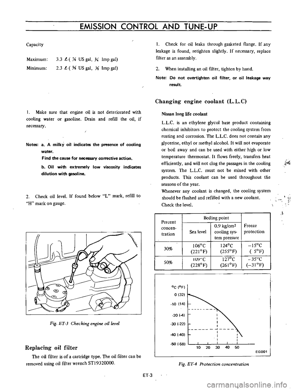
2
Check
oil
level
If
found
below
L
mark
refill
to
H
mark
on
gauge
Fig
ET
3
Checking
engine
oil
level
Replacing
oil
filter
The
oil
ftIter
is
of
a
cartridge
type
The
oil
filter
can
be
removed
using
oil
ftIter
wrench
STl9320000
Check
for
oil
leaks
through
gasketed
flange
If
any
leakage
is
found
retighten
slightly
If
necessary
replace
filter
as
an
assembly
2
When
installing
an
oil
filter
tighten
by
hand
Note
Do
not
overtighten
oil
filter
or
oil
leakage
way
result
Changing
engine
coolant
L
L
C
Nissan
long
life
coolant
LLC
is
an
ethylene
glycol
base
product
containing
chemical
inhibitors
to
protect
the
cooling
system
from
rusting
and
corrosion
The
L
L
C
does
not
contain
any
glycerine
ethyl
or
methyl
alcohol
It
will
not
evaporate
or
boil
away
and
can
be
used
with
either
high
or
low
temperature
thermostat
It
flows
freely
transfers
heat
efficiently
and
will
not
clog
the
passages
in
the
cooling
system
The
LL
C
must
not
be
mixed
with
other
products
This
coolant
can
be
used
throughout
tlie
seasons
of
the
year
Whenever
any
coolant
is
changed
the
cooling
system
should
be
flushed
and
refilled
with
a
new
coolant
Check
the
level
J
Percent
Boiling
point
0
9
kgfcm2
Freeze
concen
tration
Sea
level
cooling
sys
protection
tern
pressure
30
1060
C
I
240C
15OC
221OF
255OF
5OF
50
IUY
C
1270C
35
C
2280
F
2610F
3IOF
DC
OF
0
321
10
14
20141
50
58
I
I
I
I
1
I
I
1
30
1
22
40
401
40
10
30
50
20
EGOOl
Fig
ET
4
Protection
concentration
ET
3
Page 309 of 513

ENGINE
Checking
cooling
system
hoses
and
connections
Check
cooling
system
hoses
and
fiHings
for
loose
connections
and
deterioration
Retighten
or
replace
as
necessary
Inspection
of
radiator
cap
Apply
reference
pressure
0
9
kg
cm1
13
psi
to
radiator
cap
by
means
of
a
cap
tester
to
see
if
it
is
in
good
condition
Replace
cap
assembly
if
necessary
ET012
Fig
ET
5
Testing
radiator
cap
Cooling
system
pressure
test
With
radiator
cap
removed
apply
reference
pressure
1
6
kg
cm1
23
psi
to
the
cooling
system
bv
means
of
a
tester
to
check
for
leaks
at
the
system
compo
nents
Water
capacity
with
heater
4
9
l
I
Y
US
gal
l
i
Imp
gal
without
heater
4
2
l
I
i
US
gal
i
Imp
gal
Fig
ET
6
Testing
cooling
system
pressure
Checking
vaccum
fittings
hoses
and
connections
Check
vacuum
system
fittings
and
hoses
for
loose
connections
and
deterioration
Retighten
if
necessary
replace
any
deteriorated
parts
Checking
engine
compression
Compression
pressure
test
Note
To
test
cylinder
compression
remove
all
spark
plugs
and
hold
tester
fitting
tightly
in
spark
plug
hole
of
cylinder
The
tester
is
used
to
determine
whether
cylinder
can
hold
compression
or
whether
there
is
excessive
leakage
past
rings
etc
I
Td10
l
y
Fig
ET
7
Testing
compression
pressure
Test
compression
with
engine
warm
all
spark
plugs
removed
and
throttle
and
choke
valve
opened
No
cylinder
compression
should
be
less
than
80
of
highest
cylinder
s
Excessive
variation
between
cyl
inders
accompanied
by
low
speed
missing
of
the
cylinder
usually
indicates
a
valve
not
properly
seating
or
a
broken
piston
ring
Low
pressures
even
though
uniform
may
indicate
worn
rings
This
may
be
accompanied
by
excessive
oil
consumption
Test
conclusion
If
one
or
more
cylinders
read
low
inject
about
one
tablespoon
of
enigne
oil
on
top
of
the
pistons
in
low
ET
4
Page 330 of 513

EMISSION
CONTROL
AND
TUNE
UP
SERVICE
DATA
AND
SPECIFICATIONS
Valve
clearance
Hot
Intake
Exhaust
mm
in
rom
in
rom
in
kg
lb
0
35
0
014
0
35
0
014
10
to
15
0
394
to
0
591
10
22
Fan
belt
tension
Tightening
torque
Cold
Cylinder
head
bolts
kg
m
ft
lb
1st
turn
2nd
turn
Re
tightening
torque
Hot
Manifold
nuts
Carburetor
nuts
4
0
to
4
5
29
to
33
5
5
to
6
0
40
to
43
6
0
to
6
5
43
to
47
0
9
to
I
4
6
5
to
10
0
5
to
1
0
3
6
to
7
2
1
5
to
2
0
II
to
14
Spark
plugs
Oil
capacity
of
engine
including
oil
ftIter
Maximum
L
US
gal
Imp
gal
L
US
gal
Imp
gal
3
3
U
14
2
3
Ii
Minimum
Water
capacity
of
cooling
system
Without
heater
L
US
gal
Imp
gal
With
heater
L
US
gal
Imp
gal
4
2
1
U
4
9
I
4
11
12
5
to
14
5
I78
to
206
350
Compression
pressure
at
rpm
kg
em
psi
Battery
specific
gravity
Permissible
value
Fully
charged
value
at
200C
680F
Frigid
climates
Tropical
climates
Other
elima
tes
Over
1
22
Over
1
18
Over
1
20
1
28
1
23
1
26
Ignition
timing
degree
Distributor
50
B
T
D
C
Condenser
capacity
mm
in
degrees
IlF
Micro
Farad
0
45
to
0
55
0
018
to
0
022
49
to
55
0
22
5
Point
gap
Dwell
angle
Condenser
insulation
resistance
Mil
Mega
ohms
ET
25
Page 335 of 513
Air
intake
system
in
trouble
Overheating
Overcooling
Others
NOISY
ENGINE
Car
knocking
Car
knock
when
coasting
ENGINE
Diny
ur
clogged
fuel
strainer
Fuel
pump
will
not
work
properly
Clogged
carburetor
jets
Clogged
air
cleaner
Air
inhaling
from
manifold
gasket
or
carbu
retor
gasket
Insufficient
coolant
Loosened
fan
belt
Worn
or
defective
fan
belt
Defective
thermostat
Defective
water
pump
Clogged
or
leaky
radiator
Defective
radiator
filler
cap
Air
mixing
into
cooling
system
Improper
grade
engine
oil
Incorrect
ignition
timing
Defective
carburetor
lean
mixture
Defective
thermostat
Low
octane
fuel
Improper
tire
pressure
Dragging
brake
Slipping
clutch
Overloading
to
engine
Carbon
knocking
Timing
knocking
Fuel
knocking
Preignition
misusing
of
spark
plug
Incorrect
throttle
opener
adjustment
Trouble
in
PCV
valve
ET
30
Replace
Repair
or
replace
Disassemble
and
clean
Replace
element
Replace
gasket
Replenish
Adjust
Replace
Replace
Replace
Flush
repair
or
replace
Replace
Retighten
each
part
of
cooling
system
Replace
with
proper
grade
oil
Adjust
Overhaul
carburetor
Replace
Replace
with
specified
octane
fuel
Adjust
to
the
specified
pressure
Adjust
Adjust
Use
right
gear
in
driving
Disassemble
cylinder
head
and
remove
carbon
Adjust
ignition
timing
Use
specified
octane
fuel
Use
specified
spark
plug
Adjust
throttle
opener
Replace
PCV
valve
Page 342 of 513
ENGINE
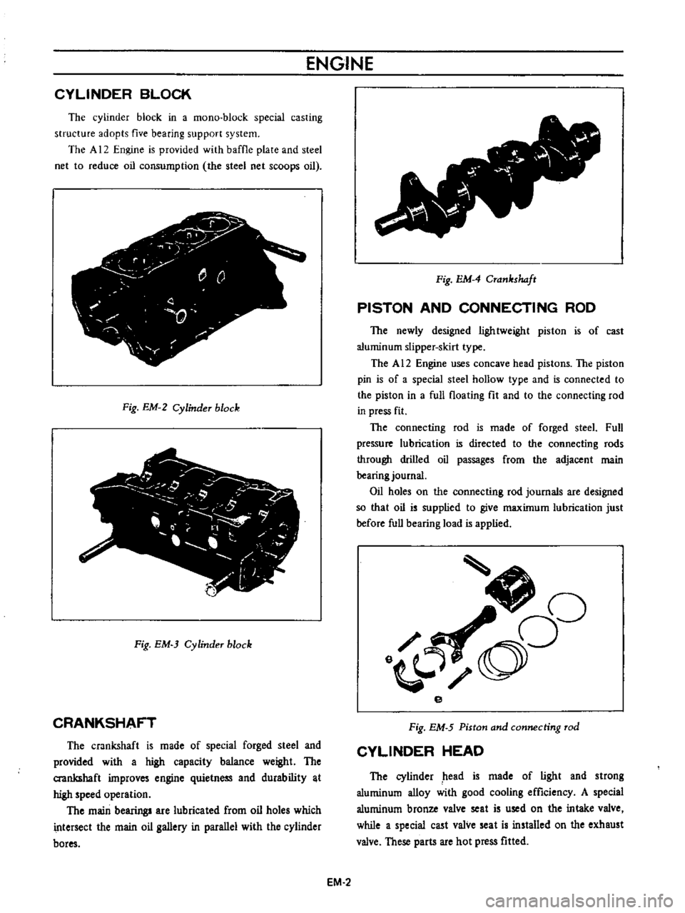
CYLINDER
BLOCK
The
cylinder
block
in
a
mono
block
special
casting
structure
adopts
five
bearing
support
system
The
A
12
Engine
is
provided
with
baffle
plate
and
steel
net
to
reduce
oil
consumption
the
steel
net
scoops
oil
j
y
r
0
Q
0
T
Fig
EM
2
Cylinder
block
Fig
EM
3
Cylinder
block
CRANKSHAFT
The
crankshaft
is
made
of
special
forged
steel
and
provided
with
a
high
capacity
balance
weight
The
crankshaft
improves
engine
quietness
and
durability
t
high
speed
operation
The
main
bearing
are
lubricated
from
oil
holes
which
intersect
the
main
oil
gallery
in
parallel
with
the
cylinder
bores
v
Fig
EM
4
Crankshaft
PISTON
AND
CONNECTING
ROD
The
newly
designed
lightweight
piston
is
of
cast
aluminum
slipper
skirt
type
The
A
12
Engine
uses
concave
head
pistons
The
piston
pin
is
of
a
special
steel
hollow
type
and
is
connected
to
the
piston
in
a
full
floating
fit
and
to
the
connecting
rod
in
press
fit
The
connecting
rod
is
made
of
forged
steeL
Full
pressure
lubrication
is
directed
to
the
connecting
rods
through
drilled
oil
passages
from
the
adjacent
main
bearing
journal
Oil
holes
on
the
connecting
rod
journals
are
designed
so
that
oil
is
supplied
to
give
maximum
lubrication
just
before
full
bearing
load
is
applied
J
oO
o
e
Fig
EM
5
Piston
and
connecting
rod
CYLINDER
HEAD
The
cylinder
head
is
made
of
light
and
strong
aluminum
alloy
with
good
cooling
efficiency
A
special
aluminum
bronze
valve
seat
is
used
on
the
intake
valve
while
a
special
cast
valve
seat
is
installed
on
the
exhaust
valve
These
parts
are
hot
press
fitted
EM
2
Page 386 of 513
r
r
J
j
r
I
1
Bi
l
it
1
J
f
J
f
f
r
c
i
I
i
f
4
Y
fj
r
i
SER
V
E
o
r
irJ
fl
i
rt
r
f
c
V
A
M
I
I
U
I
L
WI
F
or
i
7
v
I
1II
i
r
JIt
l
W
1
pI
r
r
1
r
0
j
j
j
t
r
7
f
of
JI
p
Xjlf
ii
i
t
oI
c
J
SECTION
CO
DATSUN
1200
MODEL
8110
SERIES
COOLING
SYSTEM
LNISSAN
I
NI55AN
MOTOR
CO
LTD
TOKYO
JAPAN
COOLING
SYSTEM
co
1
Page 387 of 513
COOLING
SYSTEM
COOLING
SYSTEM
CONTENTS
DESCRIPTION
WATER
PUMP
Removal
THERMOSTAT
Removal
Inspection
CO
1
CO
2
CO
2
CO
2
CO
2
CO
2
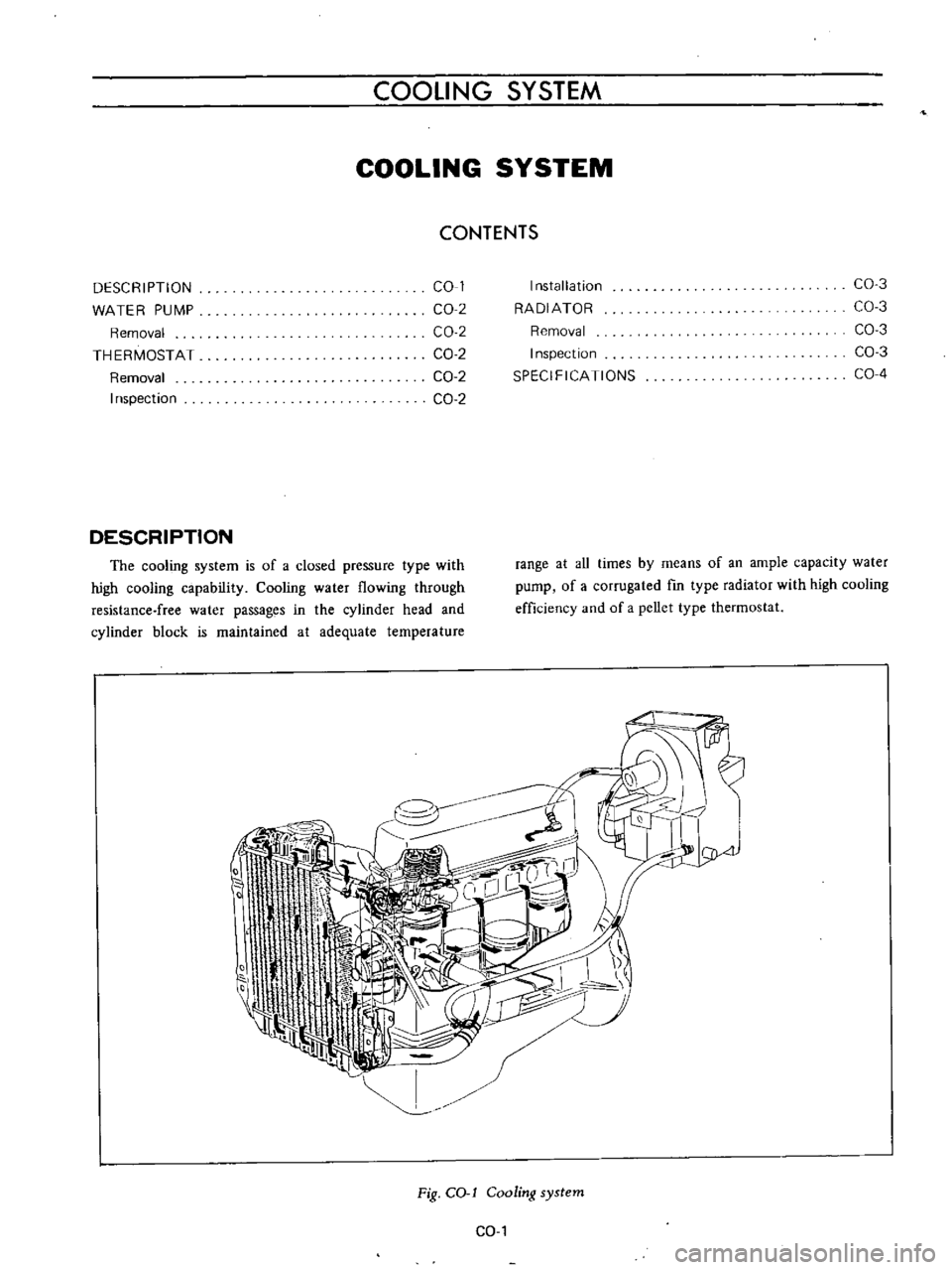
DESCRIPTION
The
cooling
system
is
of
a
closed
pressure
type
with
high
cooling
capability
Cooling
water
flowing
through
resistance
free
water
passages
in
the
cylinder
head
and
cylinder
block
is
maintained
at
adequate
temperature
Installation
RADIATOR
Removal
Inspection
SPECIFICATIONS
CO
3
CO
3
CO
3
CO
3
CO
4
range
at
aU
times
by
means
of
an
ample
capacity
water
pump
of
a
corrugated
fm
type
radiator
with
high
cooling
efficiency
and
of
a
pellet
type
thermostat
I
I
I
0
Jrl
oA
Fig
COol
Cooling
system
CO
I
Page 388 of 513
ENGINE
WATER
PUMP
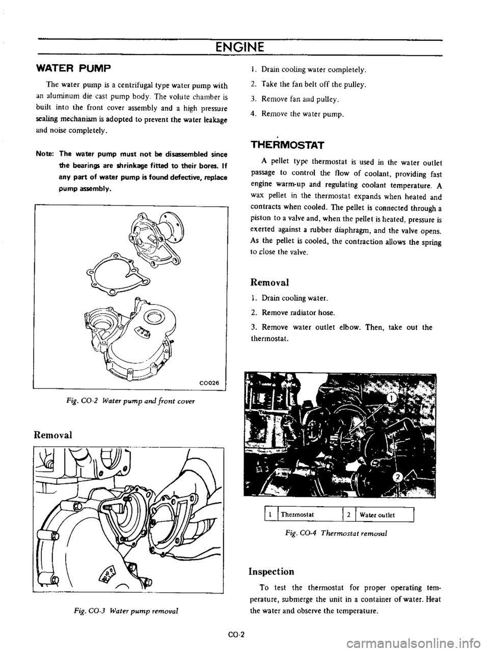
The
water
pump
is
a
centrifugal
type
water
pump
with
an
aluminum
die
cast
pump
body
The
volute
chamber
is
built
into
the
front
cover
assembly
and
a
high
pressure
sealing
mechanism
is
adopted
to
prevent
the
water
leakage
and
noise
completely
Note
The
water
pump
must
not
be
disassembled
since
the
bearings
are
shrinkage
fitted
to
their
bores
If
any
part
of
water
pump
is
found
defective
replace
pump
assembly
o
C0026
Fig
CO
2
Water
pump
and
front
cover
Removal
Fig
CO
3
Water
pump
removal
Drain
cooling
water
completely
2
Take
the
fan
belt
off
the
pulley
3
Remove
fan
and
pulley
4
Remove
the
water
pump
THERMOSTAT
A
pellet
type
thermostat
is
used
in
the
wa
ter
outlet
passage
to
control
the
flow
of
coolant
providing
fast
engine
warm
up
and
regulating
coolant
temperature
A
wax
pellet
in
the
thermostat
expands
when
heated
and
contracts
when
cooled
The
pellet
is
connected
through
a
piston
to
a
valve
and
when
the
peUet
is
heated
pressure
is
exerted
against
a
rubber
diaphragm
and
the
valve
opens
As
the
pellet
is
cooled
the
contraction
allows
the
spring
to
close
the
valve
Removal
Drain
cooling
water
2
Remove
radiator
hose
3
Remove
water
outlet
elbow
Then
take
out
the
thermostat
11
I
Thermostat
12
Water
outlet
Fig
CO
4
Thermostat
removal
Inspection
To
test
the
thermostat
for
proper
operating
tern
perature
submerge
the
unit
in
a
container
of
water
Heat
the
water
and
observe
the
temperature
CO
2