1973 DATSUN B110 ESP
[x] Cancel search: ESPPage 56 of 513

and
band
are
adversely
af
fected
Sufficient
cooling
time
should
be
given
between
each
test
for
the
four
ranges
0
2
I
and
R
Judgement
I
High
stall
revolution
more
than
standard
revolution
If
the
engine
revolution
in
staU
condition
is
higher
than
the
standard
values
it
indicates
that
one
or
more
clutches
in
the
transmission
are
slip
ping
and
therefore
nO
further
test
is
required
For
the
following
abnormalities
the
respective
causes
3re
presumed
High
rpm
in
all
ranges
Low
line
pre
ure
High
rpm
in
D
2
and
I
and
normal
rpm
in
R
Rear
clutch
slipping
High
pm
in
D
and
2
and
normal
rpm
in
lOne
way
clutch
slipping
High
rpm
in
R
only
Front
clutch
or
low
and
reverse
brake
slipping
To
determine
which
is
slipping
either
front
clutch
or
low
and
reverse
brake
a
road
test
is
needed
If
while
coasting
after
starting
with
the
lever
in
I
range
engine
braking
does
not
work
properly
it
is
deter
mined
the
low
and
reverse
brake
is
slipping
Otherwise
the
front
clutch
is
slipping
The
slipping
of
the
band
brake
is
difficult
to
ascertain
However
if
it
occurs
with
the
lever
in
2
range
the
enigne
revolution
increases
up
to
the
same
level
as
in
1st
speed
and
therefore
it
can
be
found
out
by
careful
observation
It
is
impossible
to
check
it
in
the
stall
test
Z
Standard
stall
revolution
If
the
enigne
revolution
in
stall
condition
is
within
the
standard
values
the
control
elements
are
nor
mally
operating
in
the
ranges
0
2
I
and
R
Also
the
engine
and
one
way
clutch
of
the
torque
converter
are
normal
in
perfonnance
and
operation
The
one
way
clutch
of
the
torque
Gear
shift
Propeller
shaft
rpm
D
D
1
840
to
2
340
D
DJ
3
340
to
3
840
DJ
D
3
460
to
2
960
D
0
1
790
to
1
290
D
D
330
to
830
D
OJ
l
720
to
2
220
DJ
D2
or
1
350
to
850
DJ
D
D
0
700
Max
I
I
1
860
to
1
360
CHASSIS
converter
however
sometimes
sticks
This
should
be
determined
in
the
road
test
3
Low
stall
revolution
less
than
standard
revolution
If
the
engine
revolution
in
stall
condition
is
lower
than
the
standard
values
it
indicates
that
the
engine
is
in
abnormal
condition
or
the
torque
con
verter
s
one
way
clutch
is
slipping
4
Other
I
If
the
accelerating
performance
is
poor
until
vehicle
speed
of
approxi
mately
50
km
h
30
MPH
is
attained
and
then
normal
beyond
that
speed
it
can
be
judged
that
the
torque
con
verter
s
one
way
dutch
is
slipping
2
If
the
torque
converter
s
one
way
clutch
sticks
vehicle
speed
can
not
exceed
approximately
80
km
h
Car
speed
at
gear
shift
Throttle
opening
mmHg
Kick
down
0
Half
throttle
200
Full
throttle
0
Minimum
throttle
450
I
50
MPH
in
the
road
test
In
such
a
case
the
torque
converter
oH
tempera
ture
rises
up
abnormally
and
s
o
s
pecial
care
is
required
13
If
the
transmission
does
not
operate
properly
in
all
vehicle
speeds
it
indicates
poor
engine
perfonnance
ROAD
TEST
An
accurate
knowledge
of
the
auto
matic
transmission
is
prerequisite
to
its
exact
diagnosis
by
a
road
test
It
is
recommended
to
prepare
a
diagnosis
guide
chart
in
which
are
written
the
standard
vehicle
speeds
for
each
stage
of
the
up
and
down
shiftings
Measured
vehicle
speeds
are
to
be
filled
in
the
adjoining
column
in
each
testing
Also
it
is
advisable
to
mount
a
stopper
for
positioning
the
throttle
opening
I
I
1
860
to
1
360
I
Reduce
the
speed
by
shifting
to
range
from
D
range
output
shaft
2
000
rpm
Note
Car
speed
can
be
calculated
by
the
following
fonnula
2
x
7r
x
r
x
Npx
60
v
RF
X
1
000
where
V
Car
speed
km
h
Np
Propeller
shaft
revolution
rpm
RF
Final
gear
ratio
r
Tire
effective
radius
m
11
The
ratio
of
circumference
of
a
circle
to
its
diameter
3
14
AT
52
Page 57 of 513

Checking
speed
changing
condition
The
driver
s
feeling
during
gear
changes
should
also
be
checked
at
tentively
1
A
sharp
shock
or
unsmoothness
are
felt
during
a
gear
change
2
A
gear
change
is
made
with
a
long
and
dragging
feeling
These
indicate
that
the
throttle
pressure
is
too
low
or
some
valve
connected
to
the
throttle
is
defective
Checking
items
during
speed
change
1
In
D
range
gear
changes
DI
o
D2
D3
are
effected
In
R
range
the
speed
does
not
increase
2
The
kick
down
operates
properly
3
By
moving
the
lever
from
D
into
I
gear
changes
D3
2
12
II
are
effected
In
the
ranges
12
and
II
the
engine
braking
works
properly
4
In
the
speed
does
not
in
crease
5
Should
be
quickly
fixed
at
2
range
6
In
P
vehicle
can
be
parked
properly
If
any
malfunction
occurs
in
the
second
gear
during
the
road
test
that
is
if
vehicle
shakes
drags
or
sling
in
shifting
up
from
DI
directly
to
D3
or
in
shifting
up
from
D
to
W
I
r
I
1
1
I
2
31
I
I
I
I
I
t
Lh
I
I
I
I
1000
lsOo
2000
2500
Output
shaft
speed
rpm
AUTOMATIC
TRANSMISSION
D2
the
brake
band
should
be
ad
justed
If
these
troubles
remain
after
Shift
schedule
o
Full
throttlell
e
2100
E
E
200
is
Z
cu
300
mmHg
soo
o
soo
LINE
PRESSURE
TEST
When
any
slipping
occurs
in
clutch
or
brake
or
the
feeling
during
a
speed
change
is
not
correct
the
line
pressure
must
be
checked
Measuring
the
line
pressure
is
done
by
a
pressu
re
gauge
attached
to
two
pressure
measuring
holes
after
re
moving
blind
plugs
located
at
trans
mission
case
See
Figure
AT
112
The
line
pressure
measurement
is
begun
at
idling
and
taken
step
by
step
by
enlarging
the
throttle
opening
1
A
sharp
shock
in
up
shifting
or
too
high
changing
speeds
are
caused
mostly
by
too
high
throttle
pressure
2
Slipping
or
incapability
of
opera
Line
pressure
governor
feed
pressure
At
cut
back
point
After
cut
back
Throttle
opening
under
approximately
over
approximately
15
kmfh
9
MPH
35
kmfh
22
MPH
Unit
mmHg
Unit
kg
cm2
psi
Unit
kg
cm2
psi
Full
throttle
0
94
to
11
0
134
to
156
5
5
to
6
5
78
to
92
Minimum
throttle
450
3
0
to
4
0
43
to
57
3
0
to
4
0
43
to
57
Full
throttle
0
10
0
to
12
0
142
to
171
5
5
to
7
0
78
to
100
Minimum
throttle
450
6
0
to
12
0
85toI71
5
5
to
7
0
78
to
100
Full
throttle
0
14
0
to
16
0
199
to
228
14
0
to
16
0
199
to
228
Minimum
throttle
450
3
0
to
5
5
4310
78
3
0
to
5
5
43
to
78
Range
D
2
R
the
brake
band
is
adjusted
check
the
servo
piston
seal
for
oil
leakage
3
30ixI
3500
000
AT110
Fig
A
T
llI
Shift
schedule
tion
is
mostly
due
to
oil
pressure
leakage
within
the
gear
trains
or
spool
valve
AT113
I
Line
pressure
2
Governor
reed
3
Servo
release
pressure
Fig
A
T
112
MeCJ8uring
line
pressure
Notes
a
The
line
pressure
during
idling
corresponds
to
the
oil
pressure
before
cut
down
at
minimum
throttle
b
The
oil
pressure
After
cut
back
means
that
after
the
pressure
modifier
valve
has
operated
AT
53
Page 58 of 513
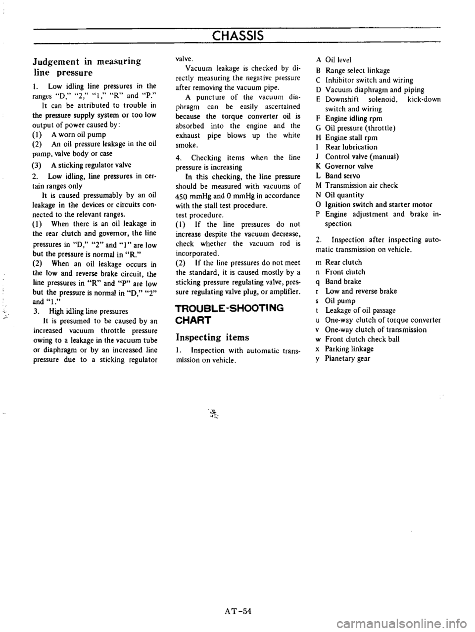
Judgement
in
measurmg
line
pressure
I
Low
idling
line
pressures
in
the
ranges
D
2
loR
and
P
It
can
be
artributed
to
trouble
in
the
pressure
supply
system
or
too
low
output
of
power
caused
by
1
A
worn
oil
pump
2
An
oil
pressure
leakage
in
the
oil
pump
valve
body
or
case
3
A
sticking
regulator
valve
2
Low
idling
line
pressures
in
cer
tain
ranges
only
It
is
caused
pressumabIy
by
an
oil
leakage
in
the
devices
or
circuits
con
nected
to
the
relevant
ranges
1
When
there
is
an
oil
leakage
in
the
rear
clutch
and
governor
the
line
pressures
in
D
2
and
I
are
low
but
the
pressure
is
normal
in
R
2
When
an
oil
leakage
occurs
in
the
low
and
reverse
brake
circuit
the
line
pressures
in
R
and
p
are
low
but
the
pressure
is
normal
in
0
2
and
I
3
High
idling
line
pressures
It
is
presumed
to
be
caused
by
an
increased
vacuum
throttle
pressure
owing
to
a
leakage
in
the
vacuum
tube
or
diaphragm
or
by
an
increased
line
pressure
due
to
a
sticking
regulator
CHASSIS
valve
Vacuum
leakage
is
checked
by
di
reetly
measuring
the
negative
pressure
after
removing
the
vacuum
pipe
A
puncture
of
the
vacuum
dia
phragm
can
be
easily
ascertained
because
the
torque
converter
oil
is
absorbed
into
the
engine
and
the
exhaust
pipe
blows
up
the
white
smoke
4
Checking
items
when
the
line
pressure
is
increasing
In
trJs
checking
the
line
pressure
should
be
measured
with
vacuums
of
450
mmHg
and
0
mmHg
in
accordance
with
the
stall
test
procedure
test
procedure
1
If
the
line
pressures
do
not
increase
despite
the
vacuum
decrease
check
whether
the
vacuum
rod
is
incorporated
2
If
the
line
pressures
do
not
meet
the
standard
it
is
caused
mostly
by
a
sticking
pressure
regulating
valve
pres
sure
regulating
valve
plug
or
amptifier
TROUBLE
SHOOTING
CHART
Inspecting
items
1
Inspection
with
automatic
trans
mission
on
vehicle
J
AT
54
A
Oil
level
B
Range
selecr
linkage
C
Inhibitor
switch
and
wiring
D
Vacuum
diaphragm
and
piping
E
Downshift
solenoid
kick
down
switch
and
wiring
F
Engine
idling
rpm
G
Oil
pressure
throttle
H
Engine
stall
rpm
I
Rear
lubrication
J
Control
valve
manual
K
Governor
valve
L
Band
servo
M
Transmission
air
check
N
Oil
quantity
o
Ignition
switch
and
starter
motor
P
Engine
adjustment
and
brake
in
spection
2
Inspection
after
inspecting
auto
matic
transmission
on
vehicle
m
Rear
clutch
n
Front
clutch
q
Band
brake
r
Low
and
reverse
brake
s
Oil
pump
Leakage
of
oil
passage
u
One
way
clutch
of
torque
converter
v
One
way
clutch
of
transmission
w
Front
clutch
check
ball
x
Parking
linkage
y
Planetary
gear
Page 80 of 513
PROPELLER
SHAFT
DIFFERENTIAL
CARRIER
C
DMark
Unit
mm
in
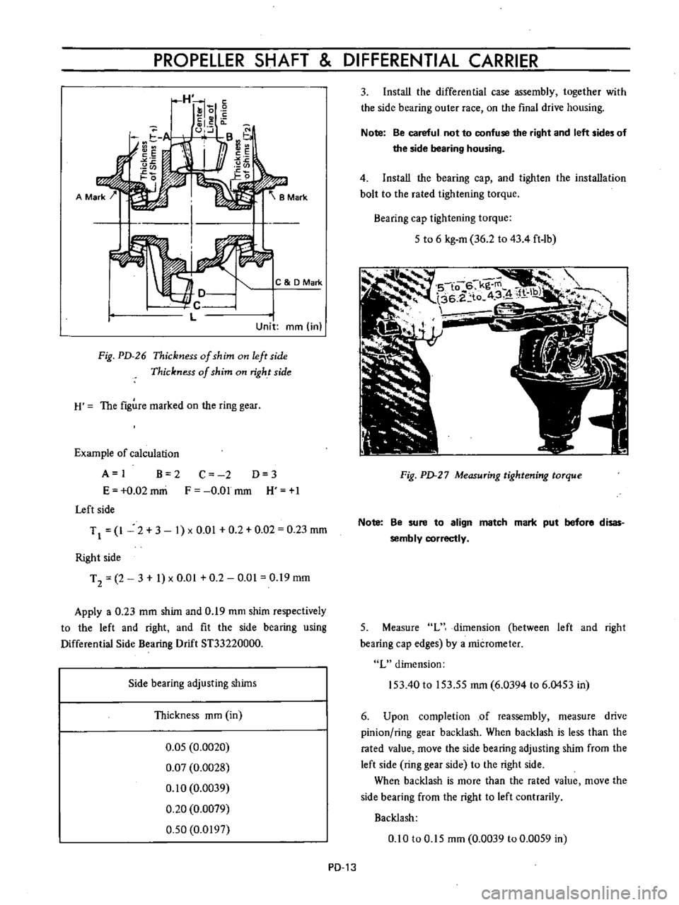
Fig
PD
26
Thickness
of
shim
on
left
side
Thickness
of
shim
on
right
side
H
The
figure
marked
on
the
ring
gear
Example
of
calculation
A
I
B
2
E
0
02
mni
Left
side
C
2
D
3
F
O
Olmm
H
1
TJ
1
2
3
1
xO
01
0
2
0
02
0
23
mm
Right
side
T
2
2
3
1
x
0
01
0
2
0
01
0
19
mm
Apply
a
0
23
mm
shim
and
0
19
mm
shim
respectively
to
the
left
and
right
and
fit
the
side
bearing
using
Differential
Side
Bearing
Drift
ST33220000
Side
bearing
adjusting
shims
Thickness
mm
in
0
05
0
0020
0
07
0
0028
0
10
0
0039
0
20
0
0079
0
50
0
0197
PD
13
3
Install
the
differential
case
assembly
together
with
the
side
bearing
outer
race
on
the
final
drive
housing
Note
Be
careful
not
to
confuse
the
right
and
left
sides
of
the
side
bearing
housing
4
Install
the
bearing
cap
and
tighten
the
installation
bolt
to
the
rated
tightening
torque
Bearing
cap
tightening
torque
5
to
6
kg
m
36
2
to
43
4
ft
1b
Fig
PD
27
Measuring
tightening
torque
Note
Be
sure
to
align
match
mark
put
before
disas
sembly
correctly
5
Measure
L
dimension
between
left
and
right
bearing
cap
edges
by
a
micrometer
L
dimension
153
40
to
153
55
mm
6
0394
to
6
0453
in
6
Upon
completion
of
reassembly
measure
drive
pinion
ring
gear
backlash
When
backlash
is
less
than
the
rated
value
move
the
side
bearing
adjusting
shim
from
the
left
side
ring
gear
side
to
the
right
side
When
backlash
is
more
than
the
rated
value
move
the
side
bearing
from
the
right
to
left
contrarily
Backlash
0
10
to
0
15
mm
0
0039
to
0
0059
in
Page 100 of 513
CHASSIS
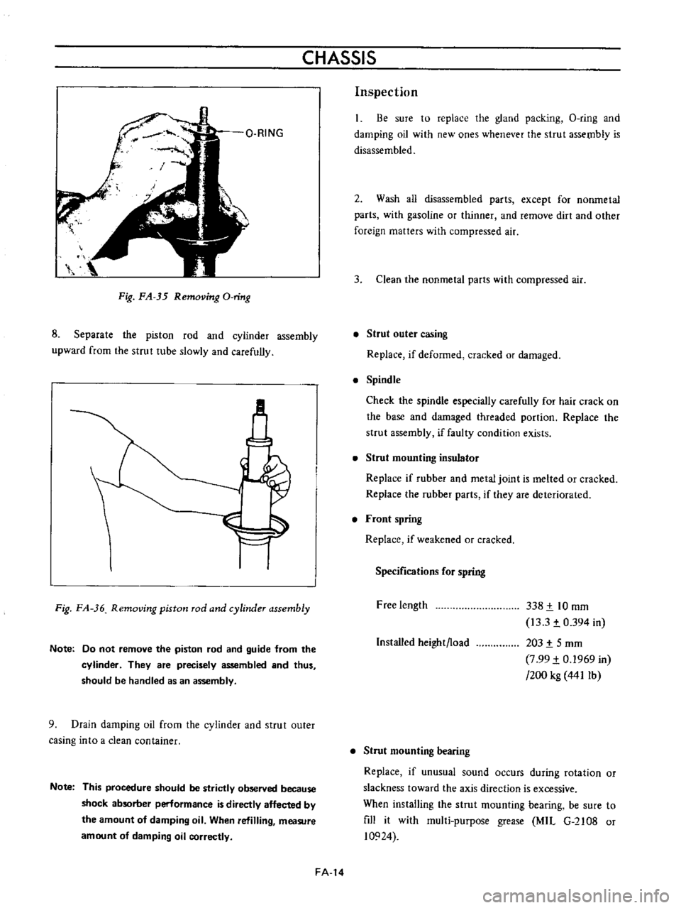
Fig
FA
35
Removing
O
ring
8
Separate
the
piston
rod
and
cyiinder
assembly
upward
from
the
strut
tube
slowly
and
carefully
M
Fig
FA
36
Removing
piston
rod
and
cylinder
assembly
Note
Do
not
remove
the
piston
rod
and
guide
from
the
cylinder
They
are
precisely
assembled
and
thus
should
be
handled
as
an
assembly
9
Drain
damping
oil
from
the
cylinder
and
strut
outer
casing
into
a
clean
container
Note
This
procedure
should
be
strictly
observed
because
shock
absorber
perlormance
is
directly
affected
by
the
amount
of
damping
oil
When
refilling
measure
amount
of
damping
oil
correctly
FA
14
Inspection
Be
sure
to
replace
the
gland
packing
O
ring
and
damping
oil
with
new
ones
whenever
the
strut
assetnb1y
is
disassembled
2
Wash
all
disassembled
parts
except
for
nonmetal
parts
with
gasoline
or
thinner
and
remove
dirt
and
other
foreign
matters
with
compressed
air
3
Clean
the
nonmetal
parts
with
compressed
air
Strut
outer
casing
Replace
if
deformed
cracked
or
damaged
Spindle
Check
the
spindle
especially
carefully
for
hair
crack
on
the
base
and
damaged
threaded
portion
Replace
the
strut
assembly
if
faulty
condition
exists
Strut
mounting
insulator
Replace
if
rubber
and
metal
joint
is
melted
or
cracked
Replace
the
rubber
parts
if
they
are
deteriorated
Front
spring
Replace
if
weakened
or
cracked
Specifications
for
spring
Free
length
338
t
10
mm
13
3
t
0
394
in
203
t
5
mm
7
99
t
0
1969
in
200
kg
441Ib
Installed
height
load
Strut
mounting
bearing
Replace
if
unusual
sound
occurs
during
rotation
or
slackness
toward
the
axis
direction
is
excessive
When
installing
the
strut
mounting
bearing
be
sure
to
fill
it
with
mul1i
purpose
grease
MIL
G
2108
or
10924
Page 111 of 513
FRONT
AXLE
FRONT
SUSPENSION
joint
Transverse
link
mounting
bolt
Tension
rod
Transverse
link
side
Body
side
Stabilizer
bar
Connecting
rod
and
transverse
link
installation
nut
Connecting
rod
and
stabilizer
bar
installation
nut
Stabilizer
bar
and
body
installation
bolt
2
2
to
3
0
15
9
to
21
7
4
0
to
5
0
28
9
to
36
2
2
2
to
3
0
15
9
to
217
5
5
to
6
5
39
7
to
47
0
0
9
to
1
2
6
5
to
8
7
0
9
to
1
2
6
5
to
8
7
0
9
to
1
2
6
5
to
8
7
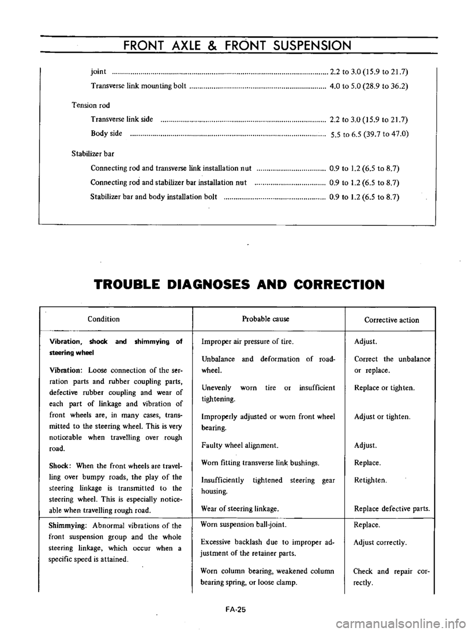
TROUBLE
DIAGNOSES
AND
CORRECTION
Condition
Vibration
shock
and
shimmying
of
steering
wheel
Vibmtion
Loose
connection
of
the
ser
ration
parts
and
rubber
coupling
parts
defective
rubber
coupling
and
wear
of
each
part
of
linkage
and
vibration
of
front
wheels
are
in
many
cases
trans
mitted
to
the
steering
wheeL
This
is
very
noticeable
when
travelling
over
rough
road
Shock
When
the
front
wheels
are
travel
ling
over
bumpy
roads
the
play
of
the
steering
linkage
is
transmitted
to
the
steering
wheeL
This
is
especially
notice
able
when
travelling
rough
road
Shimmying
Abnormal
vibrations
of
the
front
suspension
group
and
the
whole
steering
linkage
which
occur
when
a
specific
speed
is
attained
Probable
cause
Improper
air
pressure
of
tire
Unbalance
and
deformation
of
road
wheeL
Unevenly
worn
tire
or
insufficient
tightening
Improperly
adjusted
or
worn
front
wheel
bearing
Faulty
wheel
alignment
Worn
fitting
transverse
link
bushings
Insufficiently
tightened
steering
gear
housing
Wear
of
steering
linkage
Worn
suspension
ball
joint
Excessive
backlash
due
to
improper
ad
justment
of
the
retainer
parts
Worn
column
bearing
weakened
column
bearing
spring
or
loose
clamp
FA
25
Corrective
action
Adjust
Correct
the
unbalance
or
replace
Replace
or
tighten
Adjust
or
tighten
Adjust
Replace
Retighten
Replace
defective
parts
Replace
Adjust
correctly
Check
and
repair
cor
rectly
Page 157 of 513

CHASSIS
Tire
rotation
Tires
wear
unevenly
and
become
unbalanced
according
to
running
distance
Uneven
tire
wear
often
results
in
tire
noise
whkh
is
attributed
to
rear
axle
gears
bearing
ell
Meanwhile
the
front
tires
tend
to
wear
unevenly
because
of
front
wheel
alignment
Accordingly
to
equalize
tire
wear
it
is
necessary
to
rotate
tires
every
10
000
km
6
000
miles
of
operation
RIGHT
FRONT
RIGHT
REAR
r
1
Xl
L
J
LEFT
FRONT
LEFT
REAR
Fig
WT
2
Tire
rotation
The
tires
are
provided
with
tread
wear
indicator
at
six
places
around
tire
circumference
indicating
1
6
nun
0
16
in
tread
depth
When
the
tires
wear
and
then
the
marks
a
ppear
replace
them
with
new
ones
TREAD
WEAR
INDICATOR
7
TREAD
m
Y
X
W
X
v
w
WH024
Fig
WI
3
Tread
wear
illdicator
To
change
tire
with
wheel
using
a
jack
in
the
safe
manner
observe
the
following
procedures
I
Apply
parking
brake
and
block
front
wheels
when
rear
wheel
is
being
changed
2
Remove
wheel
cap
and
loosen
wheel
nuts
3
Place
jack
at
jacking
point
instructed
under
General
Information
and
raise
car
until
wheel
clears
ground
4
Remove
wheel
nuts
and
whed
from
drum
5
To
install
wheel
reverse
the
above
steps
Tighten
whed
nuts
in
criss
cross
fashion
to
8
0
to
9
0
kg
m
58
to
65
ft
lb
Note
Never
get
under
the
car
while
it
is
supported
only
by
the
jack
Always
use
safety
stands
to
support
the
side
member
of
body
construction
when
you
must
get
beneath
the
car
INSPECTION
Wheel
balance
The
wheel
and
tire
assembly
should
be
kept
balanced
statically
and
dynamically
Proper
tire
balance
is
necessary
when
driving
the
car
at
high
speeds
Consequently
the
wheel
and
tire
assembly
should
be
properly
rebalanced
whenever
puncture
is
repaired
The
wheel
and
tire
assembly
becomes
out
of
balance
according
to
uneven
tire
wear
Severe
acceleration
and
braking
or
fast
cornering
is
the
cause
of
wear
on
tire
resulting
in
unbalance
of
tire
and
wheel
assembly
The
symptom
of
unbalance
appears
as
tramp
car
shake
and
steering
trouble
To
correct
unbalance
use
proper
wheel
balancer
Maximum
allowable
unbalance
165
gr
cm
2
3
in
ol
at
rim
circumferences
Balance
weight
10
to
70
gr
0
35
to
2
47
Ol
at
10
gr
0
35
Ol
interval
Note
Be
sure
to
place
the
correct
balance
weights
on
the
inner
edge
of
rim
as
shown
in
Figure
WT
4
Wheel
and
tire
In
order
to
ensure
satisfactory
steering
condition
as
well
as
maximum
tire
life
proceed
as
follows
I
Check
wheel
rim
especially
rim
flange
and
bead
seat
for
rust
distortion
cracks
or
other
defects
which
might
cause
air
leaks
Function
of
tubeless
tire
depends
on
a
good
seal
between
tire
bead
and
wheel
rim
Thoroughly
remove
rust
dust
oxidized
rubber
or
sand
from
wheel
rim
with
wire
brush
emery
cloth
or
paper
Use
dial
gauge
to
examine
wheel
rim
for
lateral
and
diametral
run
out
WT
4
Page 161 of 513
STEERING
DESCRIPTION
The
steering
system
consists
of
recirculating
ball
type
gear
box
and
parallelogram
linkage
These
systems
give
good
response
light
handling
and
utmost
durability
Moreover
the
steering
linkage
is
equipped
with
a
torsion
rubber
system
idler
arm
which
absorbs
shock
from
the
wheel
Check
the
lubricant
of
gear
box
every
10
000
km
6
000
miles
and
replenish
recommended
oil
as
required
The
steering
linkage
should
be
greased
up
with
wheel
bearing
grease
every
50
000
km
30
000
miles
All
necessary
service
procedures
for
the
steering
lock
system
are
described
in
the
BODY
ELECTRICAL
SECTION
of
this
manual
and
therefore
no
instruction
is
given
here
STEERING
CONTENTS
REMOVAL
DISASSEMBL
Y
Ball
nut
assembly
ST
2
ST
3
ST
4
INSPECTION
AND
REPAIR
ASSEMBL
Y
AND
ADJUSTMENT
INSTALLATION
ST
4
ST
5
ST
7
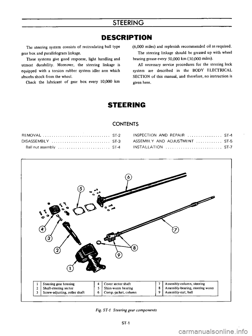
1
Steering
gear
housing
2
Shaft
steering
sector
3
Screw
adjusting
roller
shaft
4
Cover
sector
shaft
5
Shim
worm
bearing
6
Comp
jacket
column
7
Assembly
column
steering
8
Assembly
bearing
steering
worm
9
Assembly
nut
ball
Fig
ST
1
Steering
gear
components
ST
1