Page 25 of 171

liB
Oversizes
Ring
groove
width
Top
ring
Second
ring
Oil
ring
Piston
to
bore
clearanl
e
Pin
diameter
I
ength
Ll4
Ll6
Ll8
Pin
to
piston
clearance
Pin
interference
fit
in
small
end
bush
Piston
ring
height
Top
Second
Side
clearance
Ll4
Ll6
Top
ring
LI8
Top
ring
Second
ring
Ring
gap
U4
Top
ring
U4
Second
ring
Ll6
Top
ring
L
16
Second
ring
U8
Top
ring
U8
Second
ring
Oil
ring
Oil
pump
Oearance
between
inner
and
outer
rotor
Rotor
tip
clearance
Oearance
between
outer
rotor
and
body
Rotor
to
bottom
cover
clearance
Oil
pressure
at
idling
Oil
pressure
relief
valve
spring
Free
length
Fitted
length
Relief
valve
opening
pressure
24
85465485
515
mm
3
648
667
ill
86
065
86
015
mm
13
3844
33864
in
0
mm
CO
0787
in
0
mm
0
0787
in
4
0
mm
0
1
q
c
in
0
025
0
045
mm
0
0010
0
0018
in
PISTON
PIN
20
995
1
000
mm
0
8266
0
8168
in
72
00
72
25
0
001
0
Dl5
72
25
mm
2
8346
2
8445
in
73
00
mm
2
8445
2
8740
in
0
013
mm
0
00004
0
00051
in
0
033
mm
0
0006
0
0013
in
PISTON
RING
1
977
mm
0
0778
in
1
977
mm
0
0778
in
0
040
0
080
mm
0
0016
0
0031
in
0
045
0
080
mm
0
0018
0
0031
in
0
030
0
070
mm
0
0012
0
0028
in
0
23
0
38
mm
0
0091
0
0150
in
0
15
0
30
mm
0
0059
0
0118
in
0
25
0
40
mm
0
0098
0
0157
in
0
15
0
30
mm
0
0059
0
0118
in
0
35
0
55
mm
0
0138
0
0217
in
0
30
0
50mm
0
0118
0
0197
in
0
30
0
90
mm
0
0118
0
0354
in
LUBRICATION
SYSTEM
Rotor
Pump
0
05
0
12
mm
0
0020
0
0047
in
less
than
0
12
mm
0
0047
in
0
15
0
21
mm
0
0059
0
0083
in
0
03
0
13
mm
0
0012
0
0051
in
0
8
2
8
kg
sq
cm
11
40
Ib
sq
ln
52
5
mm
2
067
in
34
8
mm
1
370
in
3
5
5
0
kg
sq
cm
50
71
Ib
sq
ln
Page 26 of 171

CoolIng
System
GENERAL
FAN
BELT
TENSION
FLUSHING
AND
DRAINING
THE
SYSTEM
THERMOSTAT
Testing
RADlA
TOR
Removal
GENERAL
The
cooling
system
is
pressurised
and
incorporates
a
water
pump
corrugated
fin
type
radiator
fan
and
a
pellet
type
thermostat
The
water
pump
is
of
the
centrifugal
type
and
has
an
aluminium
die
cast
body
The
volute
chamber
is
built
into
the
front
cover
assembly
and
a
high
pressure
sealing
mechanism
prevents
water
leakage
and
noise
The
fan
pulley
is
driven
by
the
V
belt
from
a
pulley
on
the
crankshaft
he
pellct
type
thermostat
enables
the
engine
to
warm
up
rapidlY
and
also
regulates
the
temperature
of
the
coolant
When
the
wax
pellet
in
the
thermostat
is
heated
it
expands
and
exerts
pressure
against
a
rubber
diaphragm
causing
the
valve
to
open
and
allow
the
coolant
to
flow
from
the
cylinder
head
back
to
the
radiator
As
the
pellet
is
cooled
itcontractsand
allows
the
spring
to
close
the
valve
thereby
preventing
coolant
from
leaving
the
cylinder
head
The
rad
ator
is
of
the
down
flow
type
with
an
expansion
tank
The
relIef
valve
in
the
radiator
filler
cap
controls
the
pressure
at
approximately
0
9
kg
sq
cm
l3Ib
sq
in
Always
try
to
avoid
removing
the
filler
cap
when
the
engine
is
hot
as
coolant
may
spray
out
and
cause
scalding
If
the
cap
must
be
removed
in
these
circumstances
use
a
lar
e
pic
c
of
cloth
to
hold
the
cap
and
turn
the
cap
sli
htlY
Walt
until
all
pressure
has
been
released
before
lifting
off
the
cap
F
AN
BELT
TENSION
The
fan
belt
drives
the
water
pump
and
alternator
as
well
as
the
fan
and
its
correct
adjustment
is
most
essential
A
loose
fan
belt
will
sl
ip
and
Y
e
r
and
most
probably
cause
overheating
alternatively
If
the
belt
IS
too
tight
the
pump
and
alternator
bearings
will
be
overloaded
The
belt
is
correctly
tensioned
if
it
can
be
depressed
by
approximately
10
mm
1
2
in
at
a
point
midway
between
the
fan
and
alternator
pulleys
See
Fig
R2
If
adjustment
is
neces
ary
slacken
the
alternator
mounting
and
adjustment
bolts
and
pivot
the
alternator
away
from
the
engine
to
tighten
the
belt
to
towards
the
engine
if
the
belt
is
to
be
slackened
NOTE
Always
apply
leverage
to
the
drive
end
housing
when
pivoting
the
alternator
and
never
to
the
diode
end
housing
or
the
alternator
will
be
damaged
Retighten
the
alternator
bolts
and
make
SUfe
that
the
belt
is
correctly
tensioned
FLUSHING
AND
DRAINING
THE
SYSTEM
The
radiator
and
water
passages
should
be
flushed
out
periodically
to
remove
the
accumulated
scale
or
sediment
Reverse
flushing
equipment
should
be
used
to
carry
out
a
completely
thorough
flushing
operation
but
the
owner
drivef
not
possessing
this
type
of
equipment
can
flush
out
the
system
in
the
following
manner
Drain
the
system
by
removing
the
radiator
filler
cap
and
opening
the
radiator
and
cylinder
block
drain
taps
Close
the
taps
again
and
refill
the
radiator
Run
the
engine
for
a
ShOft
period
and
then
rc
open
the
drain
taps
Continue
this
sequence
until
the
water
flowing
from
the
taps
is
clean
then
close
the
taps
and
refill
the
radiator
An
anti
freeze
mixture
should
always
be
used
in
Winter
time
The
Niss3n
long
life
coolant
L
L
c
is
an
ethylene
glycol
solution
containing
a
corrosion
preventative
which
can
remain
in
the
vehicle
throughout
the
year
but
must
not
be
mixed
with
other
products
It
is
advisable
to
check
the
radiator
and
heater
hoses
when
filling
with
anti
freeze
and
renew
them
if
signs
of
deterioration
are
apparent
WATER
PUMP
Replacement
The
water
pump
must
not
be
dismantled
and
should
be
renewed
if
it
becomes
faulty
The
pump
can
be
removed
in
the
following
manner
Drain
the
cooling
system
2
Take
the
fan
belt
off
the
pulley
3
Remove
the
fan
and
pulley
4
Remove
the
retaining
nuts
and
withdraw
the
water
pump
See
Fig
B
3
lnstallation
of
the
pump
is
a
reversal
of
the
removal
procedures
rERMOST
ATTesting
The
thermostat
is
located
in
the
water
outlet
passage
See
Fig
B
4
To
remove
the
unit
drain
the
cooling
system
remove
the
radiator
hose
and
the
water
outlet
elbow
Take
out
the
thermostat
25
Page 27 of 171
inter
illIl
@
Pl
i
i
n
i
II
L
Vi
It
q
n
lli
J
j
tr
rl
t
lli
3
t
11
1
i
l
Wt
r
till
I
cj
L
f0
co
7
Fig
B
l
The
cooling
system
Fig
8
2
Olecking
the
fan
belt
tension
Fig
B
3
Removing
the
water
pump
Fig
B
4
Removing
the
thermostat
26
Page 28 of 171

The
thermostat
can
be
tested
by
suspending
it
with
a
thermometer
in
a
container
ftlled
with
water
Heat
the
water
gradually
and
stir
it
to
obtain
a
uniform
temperature
Maintain
a
constant
check
of
the
temperature
and
make
sure
that
neither
the
thermostat
or
thermometer
touch
the
sides
of
the
container
or
false
readings
will
be
obtained
The
thermostat
should
begin
to
open
at
a
temperature
of
820C
1
50C
179
60F
2
70Fj
and
should
be
fully
open
with
a
maximum
valve
lift
of
8
mm
0
315
in
at
a
temperature
of
950C
2030F
When
installing
the
thermostat
apply
adhesive
to
both
sides
of
the
gasket
before
refitting
the
water
outlet
elbow
RADIATOR
Removal
Drain
the
cooling
system
as
previously
described
and
remove
the
front
grille
2
Disconnect
the
radiator
upper
hose
lower
hose
and
hose
to
the
reservoir
tank
3
Remove
the
radiator
securing
bolts
and
lift
out
the
radiator
Fig
B
4
It
should
be
noted
that
cars
fitted
with
automatic
transmission
incorporate
a
transmission
oil
cooler
which
must
be
disconnected
Installation
is
a
reversal
of
the
removal
procedure
refill
the
system
as
previously
described
FLUID
COUPLING
The
water
pump
is
equipped
with
a
fluid
coupling
on
vehicles
fitted
with
an
air
conditioner
The
fluid
coupling
Limits
the
maximum
fan
speed
to
approximately
3000
r
p
ro
and
eliminates
noise
and
loss
of
power
at
high
engine
speeds
A
fault
in
the
coupling
may
be
caused
by
the
entry
of
foreign
matter
If
a
fault
developes
the
oupling
must
be
removed
and
dismantled
and
the
interior
cleaned
by
washing
in
solvent
The
condition
of
the
seal
and
bearing
must
be
care
fully
checked
and
the
coupling
replaced
if
the
latter
items
have
become
blackened
If
oil
leaks
occur
it
will
be
necessary
to
replace
the
water
pump
assembly
with
the
coupling
After
cleaning
the
unit
refill
with
11
5
cc
silicon
oil
using
a
suitable
syringe
TechnIcal
Data
Radiator
Radiator
cap
working
pressure
Radiator
core
heightxwidth
x
thickness
1400
and
1600
cc
engines
510
body
1600
and
1800
cc
engines
610
body
Corrugated
fin
type
0
9
kg
sq
cm
13Ib
sq
in
280x488x38mm
I
LOx
19
2x
1
49
in
360x502x32mm
l4
2x19
8x1
26
in
Thermostat
valve
opening
temperature
Standard
B20C
l
BOOF
Cold
climates
880C
1900F
Tropical
climates
76
50C
l700F
Max
valve
lift
Cooling
system
capacity
With
heater
Without
heater
Cooling
system
capacity
With
heater
Above
8
mm
0
31
in
6
8litres
1
75
US
gall
1
5
Imp
gall
6
4litres
1
75
US
gall
1
375
Imp
gall
1600
and
1800
cc
engines
610
body
6
5litres
l
7
US
gall
1
375
Imp
gall
6
0
Iitres
1
625
US
gall
1
375
Imp
gall
Without
heater
27
Page 29 of 171
inter
lW
j
@lPX
TT
Y
Gw
PRIMARY
COIL
RESISTOR
I
I
l1@
l
I
IGNITION
U
SECONDARY
COIL
COIL
IS
AK
R
POIN
i
1
1
DISTRISUTOR
I
1
J
ISI
V
nl
N
I
TO
STARTER
l
1
ROTOR
HEAD
r
SPARK
PLUG
Fig
C
t
Ignition
sys
em
circuit
diagram
i
II
@
1
1
@
J
i
9
28
l
I
i
1
I
I
@
@
G
N
7
Fig
C
2lgnition
distributor
1
Shaft
assembly
2
Collar
assembly
3
Cam
assembly
4
Governor
weights
5
Governor
spring
6
Rowr
head
7
Breaker
plate
8
Contact
set
9
Tennirtal
assembly
10
Vacuum
control
J
1
Condenser
12
Distributor
cap
13
Carbon
point
14
Plate
15
CIilmp
Page 30 of 171

IgnItIon
System
DESCRII
TION
IGNITION
TIMING
IGNITION
DISTRIBUTOR
Maintenance
ADJUSTING
THE
CONTACT
BREAKER
GAP
CENTRIFUGAL
ADVANCE
MECHANISM
VACUUM
ADVANCE
MECHANISM
IGNITION
DISTRIBUTOR
Removal
and
Dismantling
IGNITION
DISTRIBUTOR
Assembling
and
Installation
SPARKING
PLUGS
DESCRII
TION
The
ignition
circuit
comprises
the
distributor
ignition
coil
ignition
switch
spark
plugs
high
tension
lead
and
the
battery
See
Fig
C
1
The
Hitachi
distributor
is
shown
in
exploded
form
in
Fig
C
2
19niton
timing
is
automatically
regulated
by
the
distributor
centrifugal
advance
mechanism
or
vacuum
advance
mechanism
depending
upon
the
demand
made
on
the
engine
The
vacuum
advance
mechanism
operates
under
part
throttle
only
and
uses
intake
manifold
depression
to
advance
the
ignition
timing
When
the
engine
speed
is
increased
the
vacuum
is
inoperative
and
ignition
timing
is
regulated
by
the
centrifugal
advance
mechanism
The
centrifugal
advance
mechanism
uses
a
system
of
governor
weights
and
springs
which
turn
the
carn
assembly
in
on
anti
clockwise
direction
to
advance
the
ignition
timing
As
the
engine
speed
is
decreased
the
weights
move
back
and
allow
the
cam
to
return
thereby
retarding
the
ignition
timing
The
ignition
coil
is
an
oil
filled
unit
comprising
a
coil
around
which
is
wound
the
secondary
and
primary
windings
The
number
of
turns
in
the
primary
winding
provide
a
high
secondary
voltage
throughout
the
speed
range
The
resistor
is
automatically
by
passed
at
the
moment
of
starting
and
allows
the
ignition
coil
to
be
directly
connected
to
the
battery
This
applies
the
full
battery
voltage
to
the
coil
to
give
the
necessary
staTting
boost
When
the
starter
switch
is
released
the
current
flows
through
the
resistor
and
the
voltage
through
the
coil
is
dropped
for
normal
running
purposes
IGNITION
TIMING
The
ignition
timing
can
be
accurately
checked
using
a
stroboscopic
timing
light
which
should
be
connected
in
accor
dance
with
the
manufacturers
instructions
Make
sure
that
the
timing
marks
on
the
crankshaft
pulley
are
visible
if
they
are
not
visible
mark
them
with
chalk
or
white
paint
Each
mark
represents
a
50
division
of
the
crank
angle
Disconnect
the
distributor
vacuum
line
start
the
engine
and
allow
it
to
run
at
normal
idling
speed
or
slightly
below
Point
the
timing
light
at
the
timing
pointer
on
the
front
cover
Fig
C
3
The
crankshaft
pulley
groove
should
appear
to
be
stationery
and
aligned
with
the
pointer
on
the
front
cover
The
top
dead
centre
mark
is
located
at
the
extreme
right
as
shown
in
the
illustration
If
the
setting
requires
adjustment
the
distributor
flange
bolts
must
be
slackened
and
the
distributor
body
turned
clockwise
to
advance
or
anti
clockwise
to
retard
the
timing
See
Technical
Data
for
timing
settings
After
adjusting
the
timing
tighten
the
distributor
flange
bolts
and
recheck
the
timing
IGNITION
DISTRIBUTOR
Maintenance
Remove
the
distributor
cap
by
easing
away
the
two
clamps
and
examine
the
points
for
signs
of
burning
or
pitting
The
points
can
be
cleaned
if
necessary
using
a
fine
grade
of
oilstone
or
file
The
faces
of
the
points
must
be
completely
flat
and
parallel
and
all
abrasive
dust
removed
with
compressed
air
If
the
points
are
excessively
pitted
they
must
be
renewed
and
grease
applied
to
the
moving
contact
pivot
and
the
surface
of
the
cam
Ensure
that
the
distributor
cap
is
thoroughly
clean
both
inside
and
outside
A
contaminated
cap
will
promote
tracking
indicated
by
black
lines
and
caused
by
electrical
leakage
between
the
segments
on
the
inside
of
the
cap
Make
sure
that
the
carbon
button
is
not
worn
Both
the
distributor
cap
and
rotor
must
be
renewed
if
they
are
cracked
or
damaged
IGNITION
DISTRIBUTOR
Adjusting
the
contact
breaker
gap
To
adjust
the
contact
breaker
points
remove
the
distributor
cap
and
pull
the
rotor
off
the
cam
spindle
Turn
the
engine
until
the
heel
of
the
contact
breaker
arm
is
positioned
on
the
cam
lobe
the
contact
breaker
gap
is
set
to
the
maximum
in
this
position
Slacken
the
adjusting
screw
Fig
CA
insert
a
feeler
gauge
between
the
points
and
adjust
the
breaker
plate
until
the
re
quired
gap
of
0
45
0
55
mm
0
0177
0
0217
in
is
obtained
Tighten
the
adjusting
screw
and
recheck
the
setting
After
the
contact
breaker
gap
has
been
adjusted
check
the
ignition
timing
as
previously
described
The
tension
of
the
contact
breaker
should
be
0
5
0
65
kg
I
I
I
4
lb
Measure
the
tension
with
a
gauge
and
at
900
to
the
contact
breaker
arm
29
Page 31 of 171
inter
i
D
j
@
2l
Fig
C
3
Checking
the
ignition
timing
J
EARTH
LEAD
WIRE
SET
SCREW
OAmER
Fig
C
5
View
of
the
distributor
without
cap
Fig
C
7
Removing
the
retaining
pin
30
J
Fig
C
4
Adjusting
the
contact
points
gap
L
Fig
C
6
Removing
the
earn
2
1
1
I
7
V
J
J
1
Governor
weight
2
Oearance
for
start
and
nd
of
advanc
angle
1
Hook
4
GOllernor
spring
B
5
Com
plate
6
F7YWt
ight
pin
7
Hook
8
Goverrwrspring
A
9
Rotor
positioning
tip
@
Fig
C
8
Centrifugal
advance
mechanism
Page 32 of 171

CENTRIFUGAL
ADVANCE
MECHANISM
Special
equipment
is
required
to
check
the
advance
characteristics
It
is
possible
however
to
carry
out
an
exam
ination
of
the
caffi
assembly
and
the
weights
and
springs
to
ensure
that
the
earn
is
not
seizing
Lift
off
the
distributor
cap
and
turn
the
rotor
anti
clock
wise
When
the
rotor
is
released
is
should
return
to
the
fully
retarded
position
without
sticking
If
it
does
not
return
to
the
fully
retarded
position
it
will
be
necessary
to
check
for
dirt
and
weak
springs
It
should
be
noted
that
any
wear
in
the
mechanism
or
lose
of
spring
tension
will
upset
the
advance
characteristics
and
cause
unsatisfactory
engine
running
performance
over
the
speed
range
VACUUM
ADVANCE
MECHANISM
The
diaphragm
of
the
vacuum
advance
mechanism
is
mechanically
connected
to
the
contact
breaker
plate
The
rise
and
fall
of
inlet
manifold
depression
causes
the
diaphragm
to
move
the
contact
breaker
plate
to
advance
or
retard
the
ignition
If
the
vacuum
control
unit
fails
to
function
correctly
a
check
can
be
carried
out
to
ensure
that
the
contact
breaker
plate
is
moving
freely
and
that
the
three
steel
balls
at
the
top
and
oottom
of
the
plate
are
adequately
lubricated
Also
make
sure
that
the
vacuum
inlet
pipe
is
not
blocked
or
leaking
and
is
securely
tightened
Leakage
may
be
due
to
a
defective
diaphragm
which
should
be
renewed
along
with
any
other
faulty
part
of
the
mechanism
IGNITION
DlSTRffiUTOR
Removal
and
Dismantling
Disconnect
the
battery
leads
2
Disconnect
the
high
tension
lead
at
the
coil
3
Withdraw
the
high
tension
leads
from
the
distributor
cap
4
Detach
the
suction
pipe
from
the
vacuum
control
unit
5
Mark
the
position
of
the
distributor
and
rotor
remove
the
flange
mounting
bolts
and
withdraw
the
distributor
To
dismantle
the
distributor
proceed
as
follows
Take
off
the
distributor
cap
and
remove
the
rotor
Slacken
the
two
set
screws
holding
the
contact
breaker
upper
plate
Remove
the
primary
cable
terminals
and
withdraw
the
contact
set
from
the
distributor
Fig
C
S
Remove
the
vacuum
control
unit
c
Remove
the
two
screws
and
lift
out
the
contact
breaker
plate
detach
the
clamp
the
terminal
and
the
lead
To
remove
the
cam
take
out
the
centre
screw
as
shown
in
Fig
e
6
Drive
out
the
drive
pinion
retaining
pin
with
a
drift
and
hammer
Fig
e
and
remove
the
pinion
and
washer
Take
care
not
to
stretch
or
deform
the
governor
springs
when
detaching
them
from
the
weights
IGNITION
DISTRIBUTOR
Assembling
and
Installing
Assembly
is
a
reversal
of
the
dismantling
procedure
Lubricate
the
moving
contact
pivot
and
smear
the
lobes
of
the
cam
with
multi
purpose
grease
If
the
centrifugal
advance
mechanism
has
been
dismantled
the
governor
springs
and
cams
must
be
refitted
as
shown
in
Fig
e
8
The
governor
weight
pin
6
should
be
fitted
into
the
longer
of
the
two
slots
leaving
a
certain
amount
of
clearance
for
the
start
and
end
of
the
centrifugal
advance
movement
When
installing
the
distributor
take
care
to
align
the
body
and
rotor
with
the
marks
made
during
removal
The
rotor
must
be
positioned
in
its
original
location
it
will
turn
slightly
when
the
distributor
is
inserted
and
the
gear
teeth
mesh
Remove
and
replace
the
distributor
if
the
rotor
does
not
point
to
the
align
ment
mark
until
both
distributor
body
and
rotor
are
correctly
aligned
SPARKING
PLUGS
The
sparking
plugs
should
be
inspected
and
cleaned
at
regular
intervals
not
exceeding
every
10
000
km
6000
miles
New
sparking
plugs
should
be
fitted
at
approximately
20
000
km
12
000
miles
Remove
the
plugs
and
check
the
amount
of
electrode
wear
and
type
of
deposits
Brown
to
greyish
tan
deposits
with
slight
electrode
wear
indicate
that
the
plugs
are
satisfactory
and
working
in
the
correct
heat
range
Dry
fluffy
carbon
deposits
are
caused
by
too
rich
a
mixture
dirty
air
cleaner
excessive
idling
or
faulty
ignition
In
this
case
it
is
advisable
to
replace
the
plugs
with
plugs
having
a
higher
heat
range
Oily
wet
black
deposits
are
an
indication
of
oil
in
the
combustion
chambers
through
worn
pistons
and
rings
or
excessive
clearance
between
valve
guides
and
stems
The
engine
should
be
overhauled
and
hotter
plugs
installed
A
white
or
light
grey
centre
electrode
and
bluish
burned
side
electrode
indicates
engine
overheating
incorrect
ignition
timing
loose
plugs
low
fuel
pump
pressure
or
incorrect
grade
of
fuel
Colder
sparking
plugs
should
be
fitted
The
plugs
should
be
cleaned
on
a
blasting
machine
and
tested
Dress
the
electrodes
with
a
small
file
so
that
the
surfaces
of
both
electrodes
are
flat
and
parallel
Adjust
the
spark
plug
gap
to
0
8
0
9
mm
0
031
0
035
in
by
bending
the
earth
electrode
Refit
the
plugs
and
tighten
them
to
a
torque
reading
of
1
5
2
5
kgm
II
15Ib
ft
31
 1
1 2
2 3
3 4
4 5
5 6
6 7
7 8
8 9
9 10
10 11
11 12
12 13
13 14
14 15
15 16
16 17
17 18
18 19
19 20
20 21
21 22
22 23
23 24
24 25
25 26
26 27
27 28
28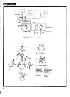 29
29 30
30 31
31 32
32 33
33 34
34 35
35 36
36 37
37 38
38 39
39 40
40 41
41 42
42 43
43 44
44 45
45 46
46 47
47 48
48 49
49 50
50 51
51 52
52 53
53 54
54 55
55 56
56 57
57 58
58 59
59 60
60 61
61 62
62 63
63 64
64 65
65 66
66 67
67 68
68 69
69 70
70 71
71 72
72 73
73 74
74 75
75 76
76 77
77 78
78 79
79 80
80 81
81 82
82 83
83 84
84 85
85 86
86 87
87 88
88 89
89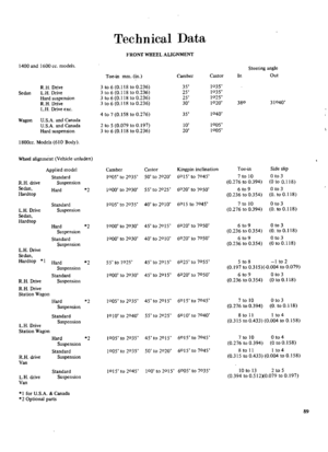 90
90 91
91 92
92 93
93 94
94 95
95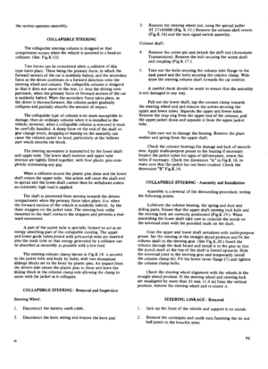 96
96 97
97 98
98 99
99 100
100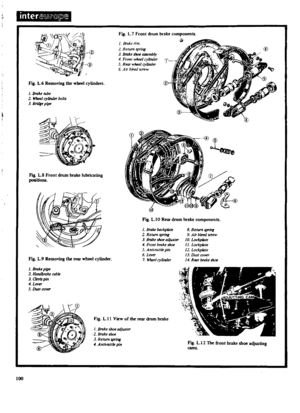 101
101 102
102 103
103 104
104 105
105 106
106 107
107 108
108 109
109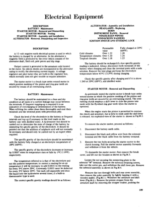 110
110 111
111 112
112 113
113 114
114 115
115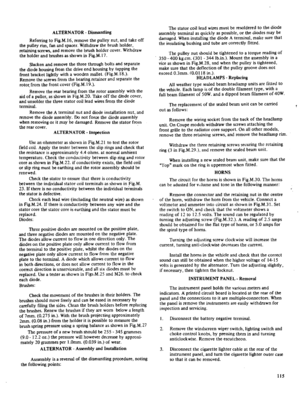 116
116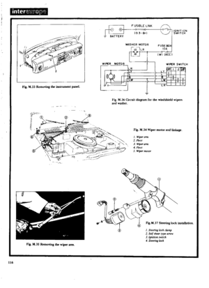 117
117 118
118 119
119 120
120 121
121 122
122 123
123 124
124 125
125 126
126 127
127 128
128 129
129 130
130 131
131 132
132 133
133 134
134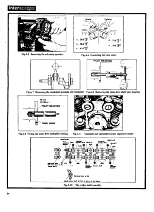 135
135 136
136 137
137 138
138 139
139 140
140 141
141 142
142 143
143 144
144 145
145 146
146 147
147 148
148 149
149 150
150 151
151 152
152 153
153 154
154 155
155 156
156 157
157 158
158 159
159 160
160 161
161 162
162 163
163 164
164 165
165 166
166 167
167 168
168 169
169 170
170

