Page 129 of 171
S
er
S
S
OfJ
e
o
2
JJ
o
t
I
I
0
a
1
t
s
i
i
1
t
t
c
t
i
6
l
w
c
a
wr
a
1
1
5
ej
J
l
r
r
el
v
p
i
i
0
L
i
1
i
i
B
s
uS
i
C
S
vI
l
r
P
ee
c
0
0
lit
l
1
i
t
i
te
ll
2
i
B
6
1
StSg
i
d
C
C
t
a
e
a
g
s
i
i
sJ
E
t
t
t
Z
ep
2
et
ai
5
i
i
g
ir
6
I
a
2
s
oi
0
11
60
l
i
i
I
l
O
ol
0
II
o
Joo
7
00
l
t
Cl1
Z
oJ
t1
1
7
r
i
5
g
t
e
H
t
i
H
o
i2
loW
z
c
I
F
J
5
i
l
7
O
10
l
H
g
a
c
G
c
t
01
JIll
z
I
Oz
V
z
J
i
lJ
0
z
z
i
S
i
l
t
tr
u
So
lZ
aII
I
v
i
n
iH
1i
1
i
t
lto
l
s
u
Ot
58
T
sfl
t
i
t
i
ii
i
t
i
O
li
J
i
i
e
P
3
o
1
P
E
a
Ii
i
Q
i
g
t
Q
11
a
5
oc
D
j
ll
g
g
l
S
B
oS
0
1
p
oj
Of
i
i
fi
e
o
d8
e
1
po
t
t
g
t
0
Q
Q
u
al
iD
3
c
ci
E
g
t
if
l
OfJ
e
v
i
ll
9
M1Ol
l
t
l
l
t
i
l
c
o
G
lo
I
6
g
lo
I
Gl
z
l
ca
VI
1
t
i
5
l
i
a
a
a
i
i
i
i
l
i
t
1
c
t
0
5
H
1
H
g
11
c5
0
1
o
rlt
i
i
g
p
E
1l
1
l
1
a
i
t
oe
Ii
t
1l
l
i
z
i
d
llC
O
5
a
1
5
lt
i
1t
i
P
ll
ep
P
S
pe
p
r
i
ii
1
1111ii
1
il
1
il
p
P
15
Page 130 of 171

TIghtenIng
Torques
LIB
engines
Three
speed
geabox
ENGINE
2
5
4
0
kgm
18
29
Ib
ft
0
3
0
4
kgm
8
13
IbJI
Ll
1
8
kgm
8
0
12
llbJt
1
6
2
5
kgm
12
18Ib
ft
I
I
1
8
kgm
8
0
12
llbJt
0
7
I
I
kgm
5
1
8
0
IbJt
17
2
lkgm
l2
15IbJI
7
0
12
0
kgm
51
87IbJI
0
8
1
0
kgm
5
8
7
2
IbJI
0
3
0
4
kgm
2
2
2
9Ib
ft
2
3
kgm
14
22IbJI
J
9
2
2
kgm
14
16IbJI
Gearbox
to
engine
Dust
cover
Front
cover
Rear
extension
Bottom
cover
Reverse
idler
shaft
Detent
ball
plug
Mainshaft
nut
Mainshaft
bearing
retainer
Speedometer
pinion
sleeve
lock
plate
Reverse
lamp
switch
Control
lever
nut
Cylinder
head
bolts
1st
stage
2nd
stage
3rd
slage
4
0
kgm
28
9Ib
ft
6
0
kgm
43
4lb
ft
6
5
8
5
kgm
47
0
61
5
Ib
ft
Connecting
rod
big
end
nuts
Ll4
Ll8
engines
Ll6
engine
Flywheel
bolls
Main
bearing
cap
bolts
Camshaft
sprocket
bolt
4
5
5
5
kgm
33
40
Ib
fl
3
2
3
8
kgm
23
27
lb
ft
14
16
kgm
l01
106Ib
ft
4
5
5
5
kgm
33
40Ib
ft
12
16
kgm
86
8
116IbJt
0
6
0
9
kgm
4
3
6
5IbJt
I
I
1
5
kgm
8
0
10
8
Ib
fl
2
3
kgm
14
5
21
7Ib
ft
5
6
kgm
36
43
Ib
ft
0
6
0
9
kgm
4
3
6
5
Ib
ft
12
16kgm
86
8
115
7
IbJt
LIB
engines
Four
speed
gearbox
Oil
sump
bolts
Oil
pump
bolts
Oil
drain
plug
Rocker
pivot
locknuts
Camshaft
locating
plate
bolts
2
5
4
0
kgm
18
29
IbJt
0
8
1
0
kgm
5
8
7
2Ib
ft
Ll
l
7kgm
8
12IbJt
Ll
I
7kgm
8
12Ib
ft
3
3
44
kgm
24
32IbJI
1
7
2
1
kgm
12
15
IbJt
2
3
kgm
14
22Ib
ft
0
5
0
7
kgm
3
6
5
IlbJI
0
8
I
I
kgm
5
8
8
0Ib
ft
0
8
Ll
kgm
5
8
8
01b
ft
0
8
1
0
kgm
5
8
7
2Ib
ft
Gearbox
to
engine
Dust
cover
Front
cover
Bottom
cover
Rear
extension
Detent
ball
plug
Reverse
lamp
switch
Lower
bracket
bolt
Shift
rod
nut
Cross
shaft
bracket
bolt
Gear
change
lever
mounting
bolt
Crankshaft
pulley
nut
Outch
mounting
bolts
L14
Ll6
Ll8
2
4
2
6kgm
174
18
8
Ib
ft
1
6
2
2
kgm
12
16Ib
fl
PROPELLER
SHAFf
AND
DIFFERENTIAL
GEARBOX
17
20kgm
l22
145IbJI
14
17
kgm
101
123Ib
ft
13
20
kgm
94
145Ib
fI
Drive
pinion
nuts
Saloon
Drive
pinion
nuts
Estate
car
Drive
pinion
nuts
Van
Ll4
and
L16
engines
Three
speed
Gearbox
Rear
extension
to
case
bolts
2
8
4
4
kgm
20
32lb
ft
Gearbox
10
engine
2
5
4
0
kgm
18
29Ib
fI
Bnttom
cover
L1
1
7
kgm
8
0
12
3
lb
ft
Ll
1
7
kgm
8
0
12
3
lb
fl
3
5
5
0
kgm
25
3
36
2
Ib
ft
1
8
2
1
kgm
13
0
15
2
Ib
ft
2
4
kgm
14
5
29
Ib
ft
0
7
L1
kgm
5
1
8
0
lb
ft
0
7
Ll
kgm
5
1
8
0
lb
fl
9
11
kgm
65
1
79
51b
ft
Crown
wheel
bolts
1400
and
1600
cc
Saloon
1400
and
1600
cc
Eslale
1800ce
Saloon
I800cc
Estate
1800cc
Van
7
8
kgm
51
58Ib
ft
4
8
5
5
kgm
35
40
Ib
ft
7
8
kgm
51
58Ib
ft
7
8
kgm
51
58Ib
ft
4
8
5
5
kgm
35
40
Ib
ft
0
9
1
2
kgm
6
5
8
7Ib
ft
1
9
2
6
kgm
13
7
18
8
IbJI
1
9
2
6
kgm
13
7
18
8
Ib
f
Front
cover
Drain
plug
Selector
lever
bolts
Side
retainer
bolts
Saloon
Drive
flange
bolts
Saloon
Reverse
lamp
switch
Idler
shaft
screw
Rear
cover
bolts
Cross
shaft
lock
pin
Final
drive
to
mounting
member
1400
and
1600cc
models
6
8
kgm
43
4
57
8IbJI
1800cc
models
5
7
kgm
36
2
50
6Ib
fI
Final
drive
to
suspension
member
6
7
kgm
43
4
51
0
Ib
ft
Final
drive
to
drive
shafls
5
6
kgm
36
431b
ft
Final
drive
flange
to
propeller
shaft
1
6
2
4
kgm
12
17
Ib
ft
Final
drive
flange
to
propeller
shaft
Eslale
1
6
2
4
kgm
l2
17Ib
ft
Mainshafl
locknut
Ll4
and
L16
engines
Four
speed
gearbox
Rearexlension
to
case
bolts
1
6
2
5
kgm
12
18Ib
ft
Gearbox
to
engine
2
5
4
0
kgm
18
29Ib
ft
Bottnm
cnver
L1
1
8
kgm
8
13
Ib
ft
Fronl
cover
L1
1
8
kgm
8
13
IbJI
Drain
plug
3
5
5
0
kgm
25
3
36
2
Ib
f
2
4
kgm
14
5
28
9IbJt
9
11
kgm
65
1
79
5Ib
ft
Final
drive
flange
to
propeller
shaft
l800cc
610
only
Reverse
lamp
switch
Mainshaft
nut
2
0
2
7
kgm
14
5
19
5
lb
ft
4
6
kgm
29
43
Ib
ft
Oil
drain
and
flller
plug
Saloon
129
Page 131 of 171

REAR
AXLE
AND
REAR
SUSPENSION
Rear
wheel
bearing
nut
Brake
backplate
25
33
kgm
181
239
IbJt
7
3
7
kgm
19
5
26
8
lb
ft
1400
1600
Shock
absorber
upper
mounting
3
kgm
l6
61b
ft
Shock
absorber
lower
mounting
3
kgm
16
6
Ih
ft
1800cc
Shock
absorber
mountings
1
6
2
2
kgm
12
161b
ft
Drive
shaft
to
differential
nuts
5
6
kgm
36
2
4341b
ft
Drive
shaft
to
rear
axle
flange
5
6
kgm
36
2
43
4lb
ft
Bump
rubber
nuts
2
8
4
0
kgm
20
29
Ib
ft
Bump
rubber
nuts
180Occ
1
6
2
2
kgm
12
16
Ib
ft
Wheel
nuts
Rear
suspension
member
mounting
nuts
8
9
kgm
58
651b
ft
10
kgm
72
Ib
ft
Differential
member
mounting
nuts
8
5
kgm
61
5Ib
ft
Suspension
arm
to
suspension
member
nuts
10
kgm
58
72
Ib
ft
Differential
to
differential
member
6
8
kgm
43
581b
fl
Propeller
shaft
flange
nuts
4
0
8
5
kgm
29
62
Ib
ft
Propeller
shaft
flange
nuts
I
800cc
2
0
2
7
kgm
14
201b
fl
Differential
to
suspension
member
6
8
kgm
43
58Ib
ft
1800cc
Estate
car
and
Van
610
Body
Shock
absorber
upper
mounting
0
9
1
2
kgm
6
5
8
7Ih
fl
Shock
absorber
lower
mounting
3
5
4
5
kgm
25
33Ib
ft
Rear
spring
U
bolt
clip
6
0
6
5
kgm
43
47
Ib
ft
Shackle
spring
6
0
6
5
kgm
43
47Ib
ft
Spring
front
pin
6
0
6
5
kgm
43
47Ib
ft
Brake
back
plate
Estate
car
Van
Differential
gear
carrier
to
axle
case
Propeller
shaft
flange
Bump
rubber
Wheel
nut
Drain
and
filler
plug
2
2
2
7
kgm
16
20IbJt
L5
2
0
kgm
II
14
Ib
ft
2
0
2
5
kgm
14
18Ib
ft
2
0
2
7kgm
14
20Ib
ft
0
9
1
2
kgm
6
5
8
7Ib
ft
9
kgm
58
65Ib
ft
4
2
6
9
kgm
30
4
49
9
lb
ft
FRONT
SUSPENSION
Front
hub
nut
3
0
3
5
kgm
21
7
25
3
Ib
ft
Disc
brake
backplate
to
strut
2
7
3
7
kgm
19
5
26
7
Ib
ft
Brake
ca1liper
bolts
7
3
9
9
kgm
52
8
71
6
Ib
ft
Brake
disc
bolts
3
9
5
3
kgm
28
381b
ft
Stabilizer
bolts
suspension
arm
side
1
2
I
7kgm
8
7
12
3
Ib
ft
130
Tension
rod
to
frame
Tension
rod
to
transverse
link
Strut
assembly
upper
nuts
Steering
lever
to
strut
Ball
joint
to
transverse
link
Ball
joint
to
knuckle
ann
Piston
rod
nut
Gland
packing
1400
and
1600
CC
models
Flange
mounting
bolts
Bali
stud
nut
Gear
ann
nut
Idler
ann
nut
Adjusting
screw
nut
Steering
gear
mounting
bolts
Idler
arm
bolts
1800cc
models
610
Body
Gear
ann
nut
Rear
cover
bolts
Sector
shaft
cover
Sector
shaft
adjusting
screw
locknut
Steering
gear
mounting
bolts
Steering
linkage
Idler
arm
to
frame
Ball
stud
nuts
Side
rod
locknuts
Column
shaft
Steering
wheel
nut
Column
clamp
COll
piing
worm
shaft
Coupling
mounting
bolts
Brake
pedal
pivot
Brake
pipe
connection
Brake
disc
bolts
Bridge
pipe
Brake
hose
to
cylinder
Brake
calliper
bolts
Wheel
cylinder
bolts
Stud
side
Hexagon
side
4
5
5
5
kgm
33
40Ib
ft
4
9
6
3
kgm
35
4
45
6
Ib
ft
3
9
5
2
kgm
28
2
37
6
Ib
fr
6
8
kgm
43
581b
ft
1
9
5
kgm
14
18Ib
fL
5
5
7
6
kgm
40
55Ib
ft
6
7
5
kgm
43
54Ib
ft
7
13
kgm
51
94Ib
ft
STEERING
1
8
2
5
kgm
13
18Ib
ft
5
5
7
6
kgm
40
55Ib
ft
12
5
14
0
kgm
90
101
lb
ft
5
5
7
6
kgm
40
55Ib
ft
1
8
2
5
kgm
13
18Ib
ft
10
kgm
72
Ib
ft
4
4
6
1
kgm
32
44Ib
ft
14
kgm
lOllb
ft
L5
2
5
kgm
II
18Ib
ft
1
5
2
5
kgm
II
18Ib
ft
2
0
2
5
kgm
14
5
18Ib
ft
6
8
kgm
43
4
57
8Ib
ft
4
4
6
1
kgm
32
44Ib
ft
5
5
7
6
kgm
40
55Ib
ft
4
4
6
1
kgm
32
44lb
ft
4
5
kgm
29
36
Ib
ft
1
3
1
8
kgm
9
4
13
0
lb
ft
4
5
kgm
29
36Ib
ft
L5
2
2
kgm
II
16Ib
ft
BRAKES
3
5
4
0
kgm
25
3
28
9
Ib
ft
1
5
1
8
kgm
10
8
13
0
lb
ft
3
9
5
3
kgm
28
2
38
3
IbJt
1
7
2
0
kgm
12
3
14
51b
fl
1
7
2
0
kgm
12
3
14
5lb
ft
7
3
9
0
kgm
52
8
65
llb
ft
0
5
0
7
kgm
3
6
5
llb
ft
1
4
1
8
kgm
10
13
Ib
ft
Page 132 of 171
inter
QDu
w
P1
SUPPLEMENT
for
the
DATSUN
1800
SERIES
C
30
MODEL
WITH
G
18
ENGINE
Contents
INTRODUCTION
G
18
ENGINE
FUEL
SYSTEM
FRONT
SUSPENSION
STEERING
BRAKING
SYSTEM
TIGhlGJ
u
GTORQUES
SI
S2
SI7
S22
S30
S36
IntroductIon
This
supplement
has
been
added
to
include
Series
C
30
model
with
the
G
18
engine
Main
changes
only
are
detailed
in
the
following
pages
and
for
aU
other
information
please
CI
to
the
Manual
s
parent
sections
SI
Page 133 of 171
interl
lli
f@
j
0
11
General
view
of
G
18
engine
Engine
installation
2
5
mm
0
0787
0
1969
n
l
Engine
nstatlstion
8
15
mm
0
3150
0
5906
1
i
1
1
1
Fig
A
3
Remo
Ying
the
canuohaft
sprocket
Fig
A
1
Front
mounting
insulator
f
A
J
A
0
0
L
I
o
i
r
1
m
if
0
1
l
r
t
I
IJ
t
o
ll
gf
Ii
o
unted
Vi
6
mm
10
2362
1
t
more
than
6
mrn
0
2362
in
Fig
A
2
Rear
mounting
insulator
Fig
A
4
Removing
the
cylinder
head
52
Page 134 of 171

GIS
DESCRIYfION
ENGINE
Removal
and
Installation
ENGINE
MOUNTING
INSULATORS
ENGINE
Dismantling
Inspection
and
Overhaul
CHAMSHAFT
AND
CAMSHAFT
BEARINGS
CYLINDER
BLOCK
PISTONS
CONNECTING
RODS
CRANKSHAFT
ENGINE
Assembling
VALVE
CLEARANCE
Adjusting
DESCRIYfION
The
G
18
engine
is
a
short
stroke
unit
with
a
displacement
of
1
815
ce
The
aluminium
alloy
cylinder
head
has
cross
flow
ports
and
a
V
shaped
valve
layout
The
single
overhead
camshaft
is
driven
from
the
crankshaft
by
a
double
row
roller
chain
at
a
reduction
ratio
of
2
I
The
crankshaft
is
a
carbon
steel
forging
and
is
provided
with
five
main
bearings
and
four
balancing
weights
Aluminium
thrust
bearings
are
located
at
the
No
2
journal
The
cast
aluminium
alloy
pistons
have
two
comp
ression
rings
and
one
oil
ring
Gudgeon
pins
are
fully
floating
in
the
piston
bores
and
are
equipped
with
circlips
at
each
end
to
limit
the
amount
of
their
travel
The
forged
steel
connecting
rods
have
weight
adjusting
bosses
at
both
large
and
small
ends
to
insure
that
the
rods
are
correctly
balanced
during
operation
The
lubricating
system
is
of
the
pressure
feed
type
with
the
oil
pump
driven
by
a
gear
on
the
crankshaft
Oil
is
delivered
to
the
main
gallery
via
a
full
flow
ftlter
ENGINE
Removal
and
Installation
Although
the
engine
can
be
removed
as
a
single
unit
it
will
prove
an
easier
operation
to
remove
the
engine
with
the
transmission
Proceed
as
follows
Fit
the
engine
slingers
ST49760000
to
the
engine
Disconnect
the
battery
cables
and
lift
out
the
battery
Drain
the
coolant
and
engine
oil
2
Place
alignment
marks
on
the
bonnet
and
hinges
remove
the
bonnet
from
the
vehicle
3
Remove
the
blow
by
hose
from
the
rocker
cover
and
take
off
the
air
cleaner
4
Disconnect
the
accelerator
linkage
and
choke
cable
from
the
carburettor
S
Detach
the
upper
and
lower
radiator
hoses
remove
the
two
brackets
from
the
core
support
and
lift
the
radia
tor
away
from
the
vehicle
The
torque
convertor
oil
pipes
must
be
disconnected
from
the
oil
cooler
if
the
vehicle
is
equip
ped
with
automatic
transmission
Detach
the
fuel
pipe
if
fitted
from
the
engine
and
heater
hose
6
Disconnect
the
electrical
wires
from
the
alternator
thennal
EngIne
OIL
PUMP
OIL
PRESSURE
RELIEF
VALVE
OIL
FILTER
EMISSION
CONTROL
SYSTEM
IGNITION
TIMING
AND
IDLING
SPEED
Emission
control
system
EMISSION
CONTROL
SYSTEM
Maintenance
IGNITION
SYSTEM
IGNITION
TIMING
IGNITION
DISTRIBUTOR
Maintenance
SPARKING
PLUGS
transmitter
the
primary
side
of
the
distributor
oil
pressure
switch
starter
motor
and
reverse
light
switch
7
Remove
the
clutch
slave
cylinder
and
its
return
spring
from
the
transmission
as
described
in
the
section
CLUTCH
8
Disconnect
the
shift
rods
and
selector
rods
then
remove
the
cross
shaft
assembly
by
detaching
the
bracket
from
the
side
member
See
GEARBOX
section
9
Disconnect
the
speedometer
cable
and
detach
the
front
exhaust
pipe
from
the
exhaust
manifold
10
Disconnect
the
propeller
shaft
and
plug
the
gearbox
rear
extension
to
prevent
the
loss
of
oil
11
Jack
up
the
gearbox
slightly
and
remove
the
rear
engine
mounting
support
Take
out
the
bolts
which
secure
the
front
mounting
insulators
to
the
cross
member
12
Attach
chains
or
wire
rope
to
the
engine
Gradually
lower
the
jack
under
the
gearbox
and
carefully
lift
and
tilt
the
engine
and
gear
box
to
clear
the
compartment
Withdraw
the
unit
making
sure
that
it
does
not
foul
the
accessories
Installation
is
a
reversal
of
the
removal
procedure
RefIll
with
the
correct
quantities
of
oil
and
coolant
when
the
engine
is
installed
ENGINE
MOUNTING
INSULATORS
Replacing
The
front
and
rear
mounting
insulators
should
be
checked
with
the
engine
installed
to
make
sure
that
the
dimensions
conform
with
those
given
in
Figs
A
I
and
A
2
To
remove
the
front
insulator
proceed
as
follows
Position
a
jack
under
the
oil
sump
Make
sure
that
the
jack
is
clear
of
the
drain
plug
and
insert
a
wooden
block
between
the
jack
and
sump
to
prevent
the
sump
from
being
damaged
Remove
the
bolts
securing
the
insulator
to
the
front
suspension
member
and
the
nut
attaching
the
insulator
to
the
engine
mounting
bracket
Raise
the
jack
slightly
and
remove
the
insulator
To
remove
the
rear
mounting
insulator
proceed
as
follows
Position
a
jack
to
take
the
weight
of
the
gearbox
and
take
out
the
bolts
connecting
the
insulator
to
the
transmission
rear
extension
housing
Remove
the
bolts
attaching
the
cross
member
to
the
underside
of
the
body
and
withdraw
the
insulator
Installation
of
both
insulators
is
a
reversal
of
the
removal
procedures
S3
Page 135 of 171
inter
l
iIJ
1lJLW
Fig
A
5
Removing
the
oil
pump
sprocket
y
x
A
S
AB10
a
1
yZ
rt
f
1
D
v
J
r
totl
35
0
1
v
J
v
0
d
3101
1
b
380
g
1
e
410
8
3
a
340
g
3
Fig
A
6
Lm
g
the
valve
seats
11
n
PILOT
BEARING
L
I
I
1
c
t
l
Fig
A
7
Measuring
the
ctankshaft
journals
and
crankpins
Fig
A
g
Removing
the
main
drive
shaft
pilot
hearing
16mm
0
236
in
PILOT
BEARING
Apply
grease
Fig
A
9
Fitting
the
main
drive
shaftpilot
hearing
Fig
A
11
Camshaft
and
camshaft
bracket
alignment
marl
s
i
IRScIItIon
Olrllole
ton
front
r
or
tM
rocbr
ft
IIWI
e
No
a
I
j
OIM
kImIII
roa
lIfIaft
oiIl
1or
nshclwn
in
tM
fil
In
Fig
A
lO
the
rocker
shaft
assembly
54
Page 136 of 171

ENGINE
Dismantling
Remove
the
engine
from
the
vehicle
as
previously
described
and
carefully
clean
the
exterior
surfaces
The
alternator
distribu
tor
and
starter
motor
should
be
removed
before
washing
Plug
the
carhurettor
air
horn
to
prevent
the
ingress
of
foreign
matter
Place
the
engine
and
transmission
on
the
engine
carrier
ST4797
0000
if
available
and
dismantle
as
follows
Remove
the
gearbox
from
the
engine
Disconnect
the
intake
manifold
water
hose
the
vacuum
hose
and
the
intake
manifold
to
oil
separator
hose
Remove
the
intake
manifold
with
the
carburettor
Fit
the
engine
attachment
ST3720OG18
to
the
cylin
der
block
and
place
tre
engine
on
the
stand
ST371
00000
Remove
the
clutch
@
Ssembly
as
described
in
the
section
CLUTCH
Remove
the
exhaust
manifold
and
heat
baffle
plate
Take
off
the
fan
blades
and
remove
the
water
pump
pulley
and
fan
belt
Remove
the
rocker
cover
hose
manifold
heat
hose
and
by
pass
hoses
Remove
the
generator
bracket
and
the
oil
fIlter
Extract
the
engine
breather
assembly
from
above
Note
that
the
breather
is
fitted
to
the
guide
and
is
installed
with
a
O
ring
which
is
pressed
into
the
cylinder
block
Flatten
the
10ckwasher
and
unscrew
the
crankshaft
pulley
nut
Withdraw
the
pulley
with
the
puller
ST44820000
if
available
but
do
not
hook
it
in
the
V
groove
of
the
pulley
Remove
the
rocker
cover
and
take
off
the
rubber
plug
located
on
the
front
of
the
cylinder
head
Straighten
the
lock
ing
washer
and
remove
the
bolt
securing
the
distributor
drive
gear
and
camshaft
sprocket
to
the
camshaft
Remove
the
drive
gear
and
take
off
the
sprocket
See
Fig
A
3
Remove
the
cylinder
head
bolts
in
reverse
order
to
the
tightening
sequence
sOOwn
in
Fig
A
18
and
lift
off
the
cylinder
head
as
an
assembly
See
Fig
A
4
Note
that
in
addition
to
the
ten
cylinder
head
bolts
there
are
also
two
bolts
securing
the
chain
cover
to
the
head
Invert
the
engine
and
remove
the
oil
sump
Remove
the
chain
cover
and
oil
flinger
Take
off
the
nut
securing
the
oil
pump
sprocket
and
withdraw
the
sprocket
with
the
chain
in
position
as
shown
in
Fig
A5
Remove
the
oil
pump
and
stramer
Note
that
two
of
the
pump
mounting
bolts
are
pipe
guides
Remove
the
timing
chain
crankshaft
sprocket
chain
ten
sioner
and
chain
stop
Remove
the
connecting
rod
caps
and
push
the
piston
and
connecting
rod
assemblies
through
the
tops
of
the
bores
Keep
all
parts
in
order
so
they
can
be
assembled
in
their
original
posi
tions
Take
out
the
flywheel
retaining
bolts
and
withdraw
the
flywheel
Remove
the
main
bearing
caps
but
take
care
not
to
damage
the
pipe
guides
Lift
out
the
crankshaft
and
main
bear
ings
noting
that
the
bearings
must
be
reassembled
in
their
original
positions
Remove
the
piston
rings
with
a
suitable
expander
and
take
off
the
gudgeon
pin
clips
The
piston
should
be
heated
to
a
temperature
of
50
to
600
122
to
1400F
before
extracting
the
gudgeon
pin
Keep
the
dismantled
parts
in
order
so
they
can
be
reassembled
in
their
original
positions
Remove
the
camshaft
rocker
ann
shaft
and
rocker
ann
assemblies
from
the
head
by
taking
off
the
cam
bracket
clamp
ing
nuts
It
is
advisable
to
insert
disused
bolts
in
the
No
1
and
No
5
bracket
holes
as
the
cam
bracket
will
fall
from
the
rocker
ann
shaft
when
it
is
removed
Remove
the
valve
cotters
using
the
special
tool
ST47450000
and
dismantle
the
valve
assemblies
Keep
the
parts
together
so
they
can
be
installed
in
their
original
order
ENGINE
Inspection
and
Overhaul
Cylinder
head
and
valves
Inspection
and
overhaul
procedures
can
be
carried
out
by
following
the
instructions
previously
given
for
the
L14
LI6
and
LIB
engines
noting
the
following
points
Measure
the
joint
face
of
the
cylinder
head
using
a
straight
edge
and
feeler
gauge
The
permissible
amount
of
distortion
is
0
03
mm
0
0012
in
or
less
The
surface
of
the
head
must
be
reground
if
the
maximum
limit
of
0
1
mm
0
0039
in
is
exceeded
Oean
each
valve
by
washing
in
petrol
then
carefully
examine
the
stems
and
heads
Discard
any
valves
with
worn
or
damaged
stems
Use
a
micrometer
to
check
the
diameter
of
the
stems
which
should
be
8
0
mm
0
315
in
for
both
intake
and
exhaust
valves
If
the
seating
face
of
the
valve
is
excessively
burned
damaged
or
distorted
the
valve
must
be
discarded
The
valve
seating
face
and
valve
tip
can
be
refaced
if
necessary
but
only
the
minimum
amount
of
metal
should
be
removed
Check
the
free
length
and
tension
of
each
valve
spring
and
compare
the
figures
obtained
with
those
given
in
Technical
Data
at
the
end
of
this
section
Use
a
square
to
check
the
springs
for
deformation
and
replace
any
spring
with
a
deflection
of
1
6
mm
0
0630
in
or
more
Valve
guides
Measure
the
clearance
between
the
valve
guide
and
valve
stern
The
stem
to
guide
clearance
should
be
0
025
0
055
mm
0
0010
0
0022
in
for
the
intake
valves
and
0
04
0
077
mm
0
0016
0
0030
in
for
the
exhaust
valves
The
maximum
clear
ance
limit
is
0
1
mm
0
0039
in
The
valve
guides
are
held
in
position
with
an
interference
fit
of
0
040
0
069
mm
0
0016
0
0027
in
and
can
be
removed
using
a
press
and
valve
guide
replacer
set
ST49730000
under
2
ton
pressure
This
operation
can
be
carried
out
at
room
temperature
but
will
be
more
effec
tively
performed
at
a
higher
temperature
Valve
guides
are
available
with
oversize
diameters
of
0
2
mm
0
0079
in
The
cylinder
head
guide
bore
must
be
reamed
out
at
normal
room
temperature
and
the
new
guides
pressed
in
after
heating
the
cylinder
head
to
a
temperature
of
approximately
800
C
1760F
The
standard
valve
guide
requires
a
bore
of
14
0
14
018
mm
0
551
0
552
in
and
the
oversize
valve
guide
a
bore
of
14
2
14
218
mm
0
559
0
560
in
Ream
out
the
bore
of
the
guides
to
obtain
the
desired
finish
and
clearance
Use
the
reamer
set
ST49710000
to
ream
the
bore
to
8
000
8
015
mm
0
3150
0
3156
in
The
valve
seat
surface
must
be
concentric
with
the
guide
bore
and
must
be
corrected
if
necessary
using
the
new
valve
guide
as
axis
Valve
seat
inserts
Check
the
valve
seat
inserts
for
signs
of
pitting
The
inserts
cannot
be
replaced
but
may
be
corrected
if
necessary
using
a
valve
seat
cutter
ST49720000
Scrape
the
seat
with
the
450
cutter
then
reduce
the
width
of
the
contacting
faces
using
the
150
and
600
cutters
for
the
intake
valve
inserts
and
150
cutter
for
the
exhaust
valve
inserts
Seat
correction
dimensions
are
shown
in
millimeters
in
Fig
A
6
Lap
each
valve
into
its
seat
after
correcting
the
seat
inserts
Place
a
small
quantity
of
fme
grinding
paste
on
the
seating
face
of
the
valve
and
lap
in
as
previously
described
for
the
Ll4
LI6
and
L
18
engines
S5
 1
1 2
2 3
3 4
4 5
5 6
6 7
7 8
8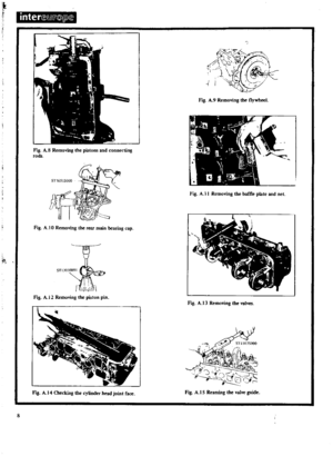 9
9 10
10 11
11 12
12 13
13 14
14 15
15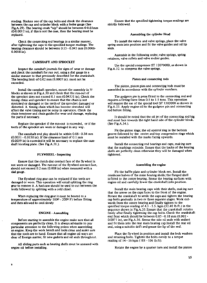 16
16 17
17 18
18 19
19 20
20 21
21 22
22 23
23 24
24 25
25 26
26 27
27 28
28 29
29 30
30 31
31 32
32 33
33 34
34 35
35 36
36 37
37 38
38 39
39 40
40 41
41 42
42 43
43 44
44 45
45 46
46 47
47 48
48 49
49 50
50 51
51 52
52 53
53 54
54 55
55 56
56 57
57 58
58 59
59 60
60 61
61 62
62 63
63 64
64 65
65 66
66 67
67 68
68 69
69 70
70 71
71 72
72 73
73 74
74 75
75 76
76 77
77 78
78 79
79 80
80 81
81 82
82 83
83 84
84 85
85 86
86 87
87 88
88 89
89 90
90 91
91 92
92 93
93 94
94 95
95 96
96 97
97 98
98 99
99 100
100 101
101 102
102 103
103 104
104 105
105 106
106 107
107 108
108 109
109 110
110 111
111 112
112 113
113 114
114 115
115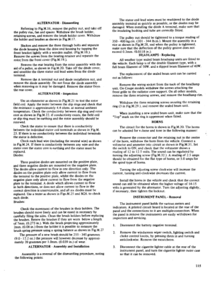 116
116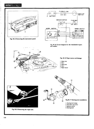 117
117 118
118 119
119 120
120 121
121 122
122 123
123 124
124 125
125 126
126 127
127 128
128 129
129 130
130 131
131 132
132 133
133 134
134 135
135 136
136 137
137 138
138 139
139 140
140 141
141 142
142 143
143 144
144 145
145 146
146 147
147 148
148 149
149 150
150 151
151 152
152 153
153 154
154 155
155 156
156 157
157 158
158 159
159 160
160 161
161 162
162 163
163 164
164 165
165 166
166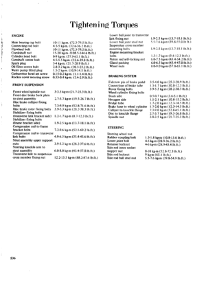 167
167 168
168 169
169 170
170


