Page 17 of 171
inter
Q1
jX
E
Fig
A
33
Installing
the
piston
pins
Fig
A
34
Piston
and
connecting
rod
cD
I
E
103470t
O
L
I
1
I
riC
J
lt
I
t
1
1
C
j
I
If
I
r
Fig
A
35
Bearing
cap
bolts
tightening
sequence
Fig
A
36
Installing
the
piston
and
connecting
rod
assembly
J
0
k2
CD
1
1
r
1
P
l
b
S
LM
J
Jr
T9T
J
I
J
@@@C@@
I
3
TimJn
mark
Lt
j
Location
hole
Oblonl
groon
I
I
Afteradju5tment
1
i
Before
adjustment
At
T
D
C
or
No
I
piston
Fig
A
37
Cylinder
head
bolts
tightening
sequence
Fig
A
38
Adjusting
the
camshaft
sprocket
Fig
A
39
Fitting
the
chain
tensioner
Fig
A
40
Valve
clearance
adjusting
16
Page 18 of 171

h
W
and
connecting
rod
assemblies
Use
a
piston
ring
compressor
to
install
the
pistons
through
the
top
of
the
cylbder
bore
Make
sure
that
the
pistons
and
rings
and
the
cylinder
bores
are
lubricated
with
clean
engine
oil
The
pistons
should
be
arranged
so
that
the
F
mark
faces
to
the
front
and
with
the
piston
ring
gaps
positioned
at
1800
to
each
other
Each
piston
must
be
refitted
into
its
original
bore
NOTE
Single
inlet
valve
springs
are
used
on
the
1400
cc
engine
double
valve
springs
are
used
on
the
1600cc
and
1800
cc
engines
Screw
the
valve
rocker
pivots
with
the
locknuts
into
the
pivot
bushing
Set
the
camshaft
locating
plate
and
install
the
camshaft
in
the
cylinder
head
with
the
groove
in
the
locating
plate
directed
to
the
front
of
the
engine
Install
the
camshaft
sprocket
and
tighten
it
together
with
the
fuel
pump
earn
to
a
torque
reading
of
12
16
kgm
86
116
IbJt
a
eck
that
the
camshaft
end
play
is
within
the
specified
limits
Install
the
rocker
arms
using
a
screwdriver
to
press
down
the
valve
springs
and
fit
the
valve
rocker
springs
Gean
the
joint
faces
of
the
cylinder
block
and
head
thoroughly
before
installing
the
cylinder
head
Turn
the
crank
shaft
until
the
No
1
piston
is
at
T
D
C
on
its
compression
stroke
and
make
sure
that
the
camshaft
sprocket
notch
and
the
oblong
groove
in
the
locating
plate
are
correctly
positioned
Care
should
be
taken
to
ensure
that
the
valves
are
clear
from
the
heads
of
the
pistons
The
crankshaft
and
camshaft
must
not
be
rotated
separately
or
the
valves
will
strike
the
heads
of
the
pistons
Temporarily
tighten
the
two
cylinder
head
bolts
1
and
2
in
Fig
A
37
to
a
torque
reading
of
2
kgm
14
5
lb
ft
Fit
the
crankshaft
sprocket
and
distributor
drive
gear
and
install
the
oil
thrower
Ensure
that
the
mating
marks
on
the
crankshaft
sprocket
face
towards
the
front
Install
the
timing
chain
making
sure
that
the
crankshaft
and
camshaft
keys
are
XJinting
upwards
The
marks
on
the
timing
chain
must
be
aligned
with
the
marks
on
the
right
hand
side
of
the
crankshaft
and
camshaft
sprockets
It
should
be
noted
that
three
location
holes
are
provided
in
the
camshaft
sprocket
See
Fig
A
38
The
camshaft
sprocket
being
set
to
the
No
2
location
hole
by
the
manufacturers
A
stretched
chain
will
however
affect
the
valve
timing
and
if
this
occurs
it
will
be
necessary
to
set
the
camshaft
to
the
No
3
location
hole
in
the
camshaft
sprocket
The
chain
can
be
checked
by
turning
the
engine
until
the
No
1
piston
is
at
T
D
C
on
its
compression
stroke
In
this
position
adjustment
will
be
required
if
the
location
notch
on
the
camshaft
sprocket
is
to
the
left
of
the
groove
on
the
camshaft
locating
plate
as
shown
in
the
illustration
The
correction
is
made
by
setting
the
camshaft
on
the
No
3
location
hole
in
the
camshaft
sprocket
the
No
3
notch
should
then
be
to
the
right
of
the
groove
and
the
valve
timing
will
have
to
be
set
using
the
No
3
timing
mark
Install
the
chain
guide
and
chain
tensioner
when
the
chain
is
located
correctly
There
should
be
no
protrusion
of
the
chain
tensioner
spindle
See
Fig
A
39
A
new
tensioner
must
be
fitted
if
the
spindle
protrudes
Press
a
new
oil
seal
into
the
timing
cover
and
fit
the
cover
into
position
using
a
new
gasket
Apply
sealing
compound
to
the
front
of
the
cylinder
block
and
to
the
gasket
and
to
the
top
of
the
timing
cover
Ensure
that
the
difference
in
height
between
the
top
of
the
timing
cover
and
the
upper
face
of
the
cylinder
block
does
not
exceed
0
15
mm
0
006
in
Two
sizes
of
timing
cover
bolts
are
used
the
size
M8
0
315
in
must
be
tightened
to
a
torque
reading
of
1
0
1
6
kgm
7
2
17
Ib
ft
and
the
size
M6
0
236
in
to
a
torque
reading
of
0
4
0
8
kgm
2
9
81b
ft
Install
the
crankshaft
pulley
and
water
pump
tighten
the
pulley
nut
to
a
torque
reading
of
12
16
kgm
86
8
115
7Ib
ft
then
set
the
No
1
piston
at
T
D
C
on
its
compression
stroke
Finally
tighten
the
cylinder
head
bolts
to
the
specified
torque
reading
in
accordance
with
the
tightening
sequence
shown
in
Fig
A
3
The
bolts
should
be
tightened
in
three
stages
as
follows
First
stage
Second
stage
Third
stage
4
kgm
28
9
lbJt
6
kgm
43
4
IbJ
t
6
5
85
kgm
47
0
61
5lb
ft
The
cylinder
head
bolts
should
be
retightened
if
necessary
after
the
engine
has
been
run
for
several
minutes
Install
the
oil
pump
and
distributor
drive
spindle
into
the
front
cover
as
described
under
Engine
Lubrication
System
r
rf
i
Install
the
fuel
pump
water
inlet
elbow
and
front
engine
slinger
Fit
the
oil
strainer
into
position
coat
the
oil
sump
gasket
with
sealing
compound
and
fit
the
gasket
and
oil
sump
to
the
cylinder
block
Tighten
the
oil
sump
bolts
in
a
diagonal
pattern
to
a
torque
reading
of
0
6
0
9
kgm
4
3
6
5
IbJt
Adjust
the
valve
clearances
to
the
specified
cold
engine
ftgures
following
the
procedures
described
under
the
appropriate
heading
Final
adjustments
will
be
carried
out
after
the
engine
has
been
assembled
completely
and
warmed
up
to
its
nonnal
temperature
Install
the
rear
engine
slinger
exhaust
manifold
and
inlet
manifold
Refit
the
distributor
and
carburettor
assemblies
as
described
in
their
relevant
sections
Install
the
fuel
pipes
and
vacuum
hose
making
sure
that
they
are
securely
cl
ped
Refit
the
thermostat
housing
thermostat
and
water
outlet
together
with
the
gasket
Bond
the
rocker
cover
gasket
to
the
rocker
cover
using
sealant
and
fit
the
rocker
cover
to
the
cylinder
head
Install
the
spark
plugs
and
connect
the
high
tension
leads
Fit
the
left
hand
engine
mounting
bracket
and
install
the
clutch
assembly
using
the
alignment
tool
ST20600000
to
fit
the
clutch
to
the
flywheel
as
described
in
the
section
ClUfCR
Lift
the
engine
away
from
the
mounting
stand
and
into
the
engine
compartment
Install
the
alternator
bracket
adjusting
bar
alternator
fan
pulley
fan
and
fan
belt
in
the
order
given
Check
the
tension
of
the
fan
belt
by
depressing
the
belt
at
a
point
midw
y
between
the
pulleys
The
tension
is
correct
if
the
belt
is
deflected
by
8
12
mm
0
3
0
4
in
under
thumb
pressure
Fit
the
right
hand
engine
mounting
bracket
the
oil
filter
oil
pressure
switch
oil
level
gauge
and
water
drain
plug
Take
care
not
to
overtighten
the
oil
nIter
or
leakage
will
occur
Fill
the
engine
and
gearbox
to
the
correct
levels
with
recommended
lubricant
and
refill
the
cooling
system
Adjust
the
ignition
timing
and
carburettor
as
described
in
the
appro
priate
sections
17
Page 19 of 171
inter
lmi
@
jl
Fig
A
41
Engine
lubrication
circuit
i
Punch
rmrk
Oil
hole
L
Fig
A
44
Aligning
the
oil
pump
spindle
18
II
l
o
CD
I
Fig
A
42
Component
parts
of
the
oil
pump
L
Pump
body
2
Inner
rotor
and
wft
3
OutO
rotor
4
Pump
coper
5
Reliefvalve
6
Relief
valve
Jpring
7
Washer
8
S
alp
9
ConT
613ut
I
Sideclruance
2
TIp
clearance
3
Guier
10
00
body
clearance
t
4
Rotor
to
bottom
cover
cleatance
Fig
A
43
Checking
the
rotor
clearance
Page 20 of 171

VALVE
CLEARANCES
Adjusting
Incorrect
valve
clearance
will
affect
the
performance
of
the
engine
and
may
damage
the
valves
and
valve
seats
Insuf
ficient
valve
clearance
will
result
in
loss
of
power
and
may
prevent
the
valve
from
seating
properly
Excessive
clearance
causes
the
valve
to
seat
and
reduces
the
amount
of
valve
lift
This
will
result
in
noisy
operation
with
damage
to
the
valves
and
seats
Adjustment
is
made
with
the
engine
switched
off
and
should
be
carried
out
initially
with
the
engine
cold
to
allow
the
engine
to
run
Final
adjustments
are
made
after
wanning
up
the
engine
to
its
Donnal
operating
temperature
The
engine
can
be
rotated
by
removing
the
sparking
plugs
to
release
the
cylinder
compressions
then
selecting
top
gear
and
pushing
the
vehicle
backwards
and
forwards
The
cold
valve
clearances
should
be
set
to
0
20
mm
0
0079
in
for
the
inlet
valves
and
0
25
mm
0
0098
in
for
the
exhaust
valves
Check
the
clearance
between
the
valve
and
rocker
using
a
feeler
gauge
as
shown
in
Fig
A
40
Slacken
the
locknut
and
turn
the
adjusting
screw
until
the
specified
clearance
is
obtained
then
tighten
the
locknut
and
recheck
the
clearance
The
feeler
gauge
should
just
be
free
to
move
between
the
rocker
and
valve
When
the
cold
valve
clearances
have
been
set
run
the
engine
until
it
reaches
its
normal
operating
temperature
then
switch
off
and
adjust
the
valve
clearances
with
the
engine
warm
to
0
25
mm
0
0098
in
for
the
inlet
valves
and
0
30
mm
0
0118
in
for
the
exhaust
valves
ENGINE
LUBRICATION
SYSTEM
Fig
A
41
OIL
PUMP
Removal
and
Dismantling
The
rotor
type
oil
pump
is
mounted
at
the
bottom
of
the
front
timing
cover
and
driven
by
the
distributor
drive
shaft
assembly
Overhaul
of
the
pump
will
require
careful
measurement
of
the
various
clearances
to
determine
the
amount
of
wear
which
has
taken
place
If
any
part
is
found
to
be
worn
it
may
be
neces
sary
to
replace
the
entire
oil
pump
assembly
To
remove
the
oil
pump
from
the
engine
proceed
as
follows
1
Remove
the
distributor
assembly
as
described
in
the
section
IGNITION
SYSTEM
Remove
the
oil
sump
drain
plug
and
drain
off
the
engine
oil
See
under
the
heading
CHANGING
THE
ENGINE
OIL
2
Remove
the
front
stabiliser
and
the
splash
shield
board
3
Withdraw
the
securing
bolts
and
detach
the
oil
pump
body
together
with
the
drive
gear
spindle
Take
out
the
bolts
securing
the
pump
cover
to
the
pump
body
and
withdraw
the
rotors
and
drive
shaft
See
Fig
A
42
The
pin
securing
the
driven
shaft
and
inner
rotor
must
not
00
taken
out
as
the
shaft
is
press
fitted
to
the
rotor
and
the
pin
is
caulked
Unscrew
the
threaded
plug
and
withdraw
the
regulator
valve
and
spring
Oean
each
part
thoroughly
and
examine
for
signs
of
damage
or
wear
Use
a
feeler
gauge
to
check
the
side
clearances
between
the
outer
and
inner
rotors
the
clearances
at
the
tips
of
the
rotors
and
the
clearance
between
the
outer
rotor
and
the
pump
body
See
Technical
Data
for
the
relevant
clearances
The
clearances
can
be
checked
using
a
straight
edge
as
shown
in
Fig
A
43
OIL
PUMP
Assembly
and
Installation
Assembly
is
a
reversal
of
the
dismantling
procedure
Before
installing
the
oil
pump
in
the
engine
it
will
be
necessary
to
rotate
the
engine
until
the
No
1
piston
is
at
T
D
C
on
its
compression
stroke
Fill
the
pump
housing
with
engine
oil
and
align
the
punch
mark
on
the
spindle
with
the
hole
in
the
oil
pump
as
shown
in
Fig
A
44
Install
the
pump
with
a
new
gasket
and
tighten
the
securing
bolts
to
a
torque
reading
of
1
1
1
5
kgm
8
1
Ilb
ft
Replace
the
splash
shield
board
and
the
front
stabiliser
refill
the
engine
with
the
specified
amount
of
engine
oil
OIL
FILTER
The
cartridge
type
oil
filter
can
be
removed
with
the
special
tool
ST
19320000
or
a
suitable
filter
remover
Interior
cleaning
is
not
necessary
but
the
ftIter
body
and
element
must
be
repiaced
every
10
000
km
6000
miles
Be
care
ul
not
to
overtighten
the
filter
when
replacing
or
oil
leakage
may
occur
CHANGING
THE
ENGINE
OIL
After
the
fIrst
oil
change
which
should
take
place
at
1000
km
600
miles
the
oil
should
be
changed
regularly
at
5000
km
3000
miles
intervals
Draining
is
more
easily
accomplished
after
a
lengthy
run
when
the
oil
being
thoroughly
warm
will
flow
quite
freely
Stand
the
vehicle
on
level
ground
and
place
a
suitable
container
under
the
drain
plug
Remove
the
drain
plug
carefully
as
the
hot
oil
may
spurt
out
with
considerable
force
When
refIlling
the
engine
make
sure
that
the
oil
is
to
the
H
mark
on
the
dipstick
19
Page 21 of 171

Engine
model
Number
of
cylinders
Arrangement
of
cylinders
Cubic
capaci
ty
Bore
x
stroke
Arrangemen
t
of
valves
Max
B
H
P
Max
torque
Firing
order
eidlingspeed
Compression
ratio
Oil
pressure
Valve
clearance
hot
Inlet
Exhaust
Valve
clearance
cold
Inlet
Exhaust
Valve
head
diameter
Inlet
Exhaust
Valve
stem
diameter
Inlet
Exhaust
Valve
lift
Valve
spring
free
length
Valve
spring
fitted
length
Valve
spring
coil
diameter
Valve
guide
length
Inlet
Exhaust
Valve
guide
protrusion
rreclll11cal
ata
L
lJEngine
LI3
4
In
line
1296
83
0
x
59
9
3
2677
x
3583
in
Overhead
camshaft
77
at
6000
rpm
II
1
kgm
at
3600
rpm
I
342
600
rpm
8
5
1
3
8
4
2
kg
sq
em
54
60Ib
sq
in
VALVES
0
25
mm
0
010
in
0
30
mm
0
01
in
0
20
mm
0
008
in
0
25
mm
O
OIJ
in
38
mm
1
50
in
33
mm
1
30
in
8
0
mm
0
31
in
8
0
mm
0
31
in
10
0
mm
0
40
in
48
12
mm
1
89
in
40
0
mm
30
7
kg
1
57
in
67
7
lb
34
9
mm
1
37
in
59
0
mm
2
32
in
59
0
mm
2
32
in
10
4
10
6
mm
0
41
0
42
in
Valve
guide
inner
diameter
Inlet
8
00
8
l
8
mm
0
315
0
3154
in
Exhaust
8
00
8
018
mm
0
315
0
3154
in
Valve
guide
outer
diameter
Inlet
Exhaust
Valve
guide
to
stem
clearance
Inlet
Exhaust
20
11
985
11
996
mm
0
472
0
4723
in
11
985
11
996
mm
0
4172
0
4723
in
0
015
0
045
mm
0
0006
0
0018
in
0
040
0
070
mm
0
0016
0
0028
in
Valve
seat
width
Inlet
Exhaust
V
lve
seat
angle
Valve
seat
insert
interference
fit
Inlet
Exhaust
Valve
guide
interference
fit
Inlet
1
4
1
8
mm
0
055
0
071
in
1
6
2
0
mm
0
063
0
079
in
450
0
08
0
11
mm
0
0031
0
0043
in
0
06
0
10
mm
0
0024
0
0039
in
0
027
0
049
mm
0
0011
0
0019
in
CAMSHAFT
AND
TIMING
GEAR
Camshaft
end
play
Camshaft
lobe
lift
Camshaft
journal
diameter
Max
camshaft
run
out
Camshaft
bearing
to
journal
clearance
Camshaft
bearing
inner
diameter
0
08
0
38
mm
0
0011
0
0019
in
6
65
mm
0
261
in
47
949
47
962
mm
fI
8877
1
8883
in
0
05
mm
0
002
in
0
038
0
076
mm
0
0015
0
0026
in
48
000
48
016
mm
1
8898
1
8904
in
CONNECTING
RODS
Distance
from
centre
to
centre
132
97
133
03
mm
5
235
5
237
in
Bearing
shell
thickness
Standard
Big
end
side
play
Connecting
rod
bearing
running
clearance
Connecting
rod
rend
or
twist
1
498
1
506
mm
0
059
0
593
in
0
20
0
30
mm
0
008
0
012
in
0
014
0
056
mm
0
0006
0
0022
in
0
03
mm
per
100
mm
0
0012
in
per
3
937
in
CRANKSHAFT
AND
MAIN
BEARINGS
Crankshaft
material
Number
of
bearings
Main
journal
diameter
Max
journal
taper
Max
journal
out
of
round
Crankshaft
end
play
Special
forged
steel
5
54
942
54
955
mm
2
1631
2
1636
in
0
03
mm
0
0012
in
0
03
mm
0
0012
in
0
05
0
015
mm
0
002
0
0059
in
Page 22 of 171

Wear
limit
Crank
pin
journal
diameter
Max
crankpin
taper
Max
crankpin
out
of
round
Thickness
of
main
bearing
shells
0
3
mm
0
012
in
49
961
49
975
mm
1
967
1
9675
in
0
03
mm
0
012
in
0
03
mm
0
012
in
1
827
1
835
mm
0
072
0
0722
in
Main
bearing
running
clearance
0
020
0
062
mm
0
0008
0
0024
in
Max
main
bearing
running
clearance
Crankshaft
bend
limit
Material
Type
Piston
diameters
Standard
I
st
oversize
2nd
oversize
3rd
oversize
4th
oversize
5th
oversize
Width
of
ring
grooves
Top
and
second
Oil
control
Piston
running
clearance
0
12
mm
0
0047
in
0
05
mm
0
002
in
PISTONS
Cast
aluminium
Slipper
skirt
82
99
83
04
mm
3
267
3
269
in
83
22
83
27
mm
3
276
3
278
in
83
47
83
52
mm
3
286
3
288
in
83
72
83
77
mm
3
296
3
298
in
83
97
84
02
mm
3
305
3
308
in
84
47
84
52
mm
3
326
3
328
in
2
0
mm
0
08
in
4
0
mm
0
16
in
0
025
0
045
mm
0
001
0
002
in
PISTON
PIN
Pin
diameter
20
995
21
000
mm
0
8266
0
8268
in
Pin
length
72
00
72
25
mm
2
8346
2
8445
in
Pin
running
clearance
in
piston
0
008
0
010
mm
0
0003
0
0004
in
Pin
interference
fit
in
small
end
bush
0
015
0
033
mm
0
0006
0
0013
in
Piston
ring
height
Top
and
second
Oil
control
Side
clearance
in
grooves
Top
PISTON
RINGS
2
0
mm
0
08
in
4
0
mm
0
16
in
0
040
0
073
mm
0
0016
0
0029
in
Second
Oil
control
Piston
ring
gaps
Top
Second
Oil
control
Material
Distortion
of
sealing
face
Max
distortion
Valve
seat
insert
material
Inlet
Exhaust
Fit
Drive
Chain
Chain
tensioner
0
030
0
063
mm
0
0012
0
0025
in
0
025
0
063
mm
0
001
0
0025
in
0
23
0
38
mm
0
0091
0
0150
in
0
15
0
30
mm
0
006
0
012
in
0
15
0
30
mm
0
006
0
012
in
CYLINDER
HEAD
Aluminium
alloy
0
03
mm
0
0012
in
0
1
mm
0
004
in
Aluminium
bronze
Special
cast
Hot
pressed
CAMSHAFT
DRIVE
From
crankshaft
double
roller
type
Spring
and
oil
pressure
control
Engine
model
lWIN
CHOKE
CARBURE
ITOR
Outlet
diameter
Venturi
diameter
Main
jet
Main
air
bleed
Slow
running
jet
Power
jet
Float
level
Fuel
pressure
Weight
Altitude
setting
main
jet
1000
m
3300
ft
94
2000
m
6600
ft
92
3000
m
10
000
ft
89
4000
m
13
300
ft
87
5000
m
16
600
ft
85
PRIMARY
L13
SECONDARY
30mm
27x
12mm
150
90
180
26
mm
21
x
8
mm
96
80
43
40
23
I
mm
0
905
0
04
in
0
24
kg
sq
em
3
41b
sq
in
2
55
kg
5
61
lb
1
21
Page 23 of 171

TechnIcal
Data
L
14
16
and
18
Engine
GENERAL
SPECIFICATIONS
Cylinders
Displacement
L14
L16
L18
Bore
and
stroke
L14
L16
Ll8
Compression
ratio
L14
L16
single
carburettor
L16
SU
twin
carburettor
L18
single
carburettor
Ll8
SU
twin
carburettor
Valve
arrangement
Firing
order
e
idling
speed
Engine
idling
speed
with
automatic
transmission
Oil
pressure
Hot
at
2000
r
p
m
Valve
clearance
Hot
Intake
Exhaust
0
25
mm
0
0098
in
0
25
mm
0
0098
in
Valve
clearance
Cold
Intake
Exhaust
Va
head
diameter
L14
Intake
Exhaust
Vahoe
head
diameter
L16
Intake
Exhaust
0
20
mm
0
0079
in
0
20
mm
0
0079
in
38
mm
1
5361
in
33
mm
1
2992
in
42
mm
1
6535
in
33
rom
1
2992
in
Valve
head
diameter
L18
Intake
Exhaust
42
mm
1
6535
in
35
mm
1
3780
in
Valve
stem
diameter
Intake
7
965
7
980
mm
0
3136
0
3142
in
Exhaust
7
945
7
960
mm
0
3128
0
3134
in
Valve
length
L14
Intake
Exhaust
115
6
115
9mm
4
551
4
562in
115
7
116
0
mm
4
555
4
567
in
Valve
length
L16
LIB
Intake
114
9
115
2
mm
4
524
4
535
in
Exhaust
115
7
116
0
mm
4
555
4
567
in
22
4
in
line
1428
cc
87
1
cu
in
1595
cc
97
3
cu
in
1770
cc
108
0
cu
in
83
x
66
mm
3
27
x
2
60
in
83
x
73
7
mm
3
27
x
2
90
in
85
x
7B
mm
3
35
x
3
07
in
9
0
8
5
9
5
8
5
9
5
Overhead
valve
I
3
4
600
r
p
m
single
carburettor
650
r
p
m
twin
carburettor
650
r
p
m
single
carburettor
700
r
p
m
twin
carburettor
3
5
4
0
kg
sq
cm
50
57Ib
sq
in
VALVES
Valve
lift
Single
carburettor
Valve
lift
Twin
carburettor
10
0
mm
0
3946
in
10
5
mm
0
413
in
Valve
spring
free
length
LI4
Ll4
Intake
Ll4
Exhaust
outer
L14
Exhaust
inner
Valve
sprin8
free
length
L16
LIB
Outer
Inner
49
0
mm
1
929
in
49
98
mm
1
968
in
44
85
mm
1
766
in
49
98
mm
1
968
in
44
85
mm
1
766
in
59
0
mm
2
393
in
10
6
mm
0
417
in
Valve
guide
length
Valve
guide
height
from
head
surface
Valve
guide
diameter
inner
Intake
8
018
Exhaust
8
018
Valve
guide
diameter
outer
Intake
12
034
Exhaust
12
034
Valve
guide
to
stem
clearance
Intake
Exhaust
Valve
seat
width
L14
Intake
Exhaust
Valve
seat
width
L16
LIB
Intake
Exhaust
8
000
mm
0
3154
0
3150
in
clia
8
000
mm
0
3154
0
3150
in
clia
12
023
mm
0
4738
0
4733
in
clia
12
023
mm
0
4738
0
4733
in
clia
1
8
mm
1
1024
in
I
7
mm
1
0630
in
I
4
mm
0
0551
in
1
3
mm
0
0512
in
0
020
0
053
mm
0
0008
0
0021
in
0
040
0
073
mm
0
0016
0
0029
in
Page 24 of 171

Valve
seat
angle
Intake
Exhaust
Valve
seat
interference
fit
450
450
Valve
guide
interference
fit
Intake
0
027
0
049
mm
0
011
0
0019
in
Exhaust
0
027
0
049
mm
0
011
0
0019
in
Intake
Exhaust
0
081
0
113
mm
0
0032
0
0044
in
0
064
0
096
mm
0
0025
0
0038
in
CAMSHAFT
AND
TIMING
CHAIN
Camshaft
end
play
0
08
0
38
mm
0
0031
0
0150
in
Camshaft
lobe
lift
L14
Ll6
LIB
intake
with
single
carburettor
Ll6
LIB
Intake
with
twin
carburettor
L16
L18
Exhaust
6
65
mm
0
2618
in
6
65
mm
0
2618
in
7
00
mm
0
2753
in
7
00
mm
0
2753
in
47
949
47
962
mm
1
8877
1
8883
in
0
02
mm
0
0007
in
0
038
0
067
mm
0
0015
0
0026
in
Camshaft
journal
diameters
Camshaft
bend
Camshaft
journal
to
bearing
clearance
Rocker
arm
lever
ratio
L14
L16
L18
1
5
1
45
CONNECTING
RODS
Connecting
rod
centres
L14
L16
L18
136
6
mm
5
35
In
133
0
mm
5
24
in
130
35
mm
5
132
in
I
493
1
506
mm
0
0588
0
0593
in
0
20
0
30
mm
0
0079
0
0118
in
0
025
0
055
mm
0
0010
0
0022
in
less
than
0
025
mm
0
001
in
per
100
mm
2
937
in
Bearing
thickness
Big
end
play
Connecting
ro
d
bearing
clearance
Connecting
rod
bend
or
twist
CRANKSHAFI
AND
MAIN
BEARINGS
Journal
diameter
Journal
taper
and
out
of
round
Crankshaft
free
end
play
Wear
limit
Crank
pin
diameter
Crankpin
taper
and
out
of
round
Thickness
of
main
bearing
shells
Main
bearing
clearance
Wear
limit
of
clearance
Crankshaft
bend
limit
54
942
54
955
mm
2
1631
2
1636
in
less
than
0
0
I
mm
0
0004
in
0
05
0
18
mm
0
0020
0
0071
in
0
3
mm
0
0118
in
49
961
49
974
mm
1
9670
1
9675
in
less
than
0
01
mm
0
0004
in
1
822
1
835
mm
0
0717
0
0722
in
0
020
0
062
mm
0
0008
0
0024
in
0
12
mm
0
0047
in
0
05
mm
0
0019
in
PISTONS
Piston
diameter
L14
Piston
diameter
L14
L16
82
985
83
035
mm
3
2671
32691
in
84
985
85
035
mm
3
3459
3
3478
in
LI4andLl6
1
st
oversize
2nd
oversize
3rd
oversize
4th
oversize
5th
oversize
0
25
mm
0
0098
in
0
50
mm
0
0197
in
0
75
mm
0
0295
in
1
00
mm
0
0394
in
1
25
mm
0
0492
in
23
 1
1 2
2 3
3 4
4 5
5 6
6 7
7 8
8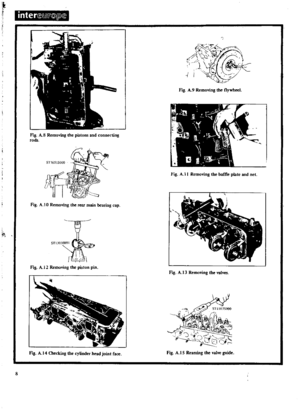 9
9 10
10 11
11 12
12 13
13 14
14 15
15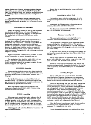 16
16 17
17 18
18 19
19 20
20 21
21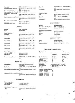 22
22 23
23 24
24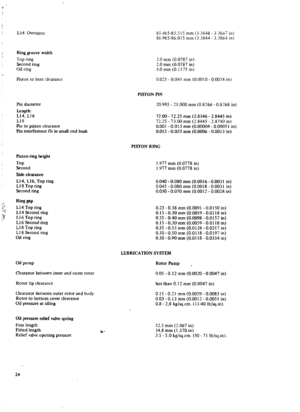 25
25 26
26 27
27 28
28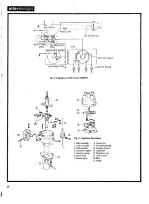 29
29 30
30 31
31 32
32 33
33 34
34 35
35 36
36 37
37 38
38 39
39 40
40 41
41 42
42 43
43 44
44 45
45 46
46 47
47 48
48 49
49 50
50 51
51 52
52 53
53 54
54 55
55 56
56 57
57 58
58 59
59 60
60 61
61 62
62 63
63 64
64 65
65 66
66 67
67 68
68 69
69 70
70 71
71 72
72 73
73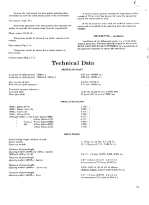 74
74 75
75 76
76 77
77 78
78 79
79 80
80 81
81 82
82 83
83 84
84 85
85 86
86 87
87 88
88 89
89 90
90 91
91 92
92 93
93 94
94 95
95 96
96 97
97 98
98 99
99 100
100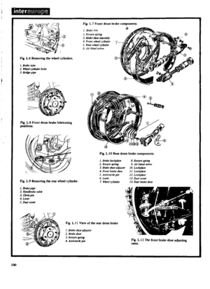 101
101 102
102 103
103 104
104 105
105 106
106 107
107 108
108 109
109 110
110 111
111 112
112 113
113 114
114 115
115 116
116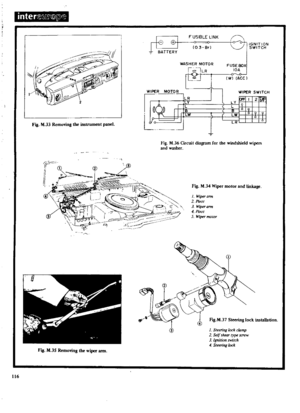 117
117 118
118 119
119 120
120 121
121 122
122 123
123 124
124 125
125 126
126 127
127 128
128 129
129 130
130 131
131 132
132 133
133 134
134 135
135 136
136 137
137 138
138 139
139 140
140 141
141 142
142 143
143 144
144 145
145 146
146 147
147 148
148 149
149 150
150 151
151 152
152 153
153 154
154 155
155 156
156 157
157 158
158 159
159 160
160 161
161 162
162 163
163 164
164 165
165 166
166 167
167 168
168 169
169 170
170
