Page 73 of 171
inter
Q1Ju@
j1l
J
Ikli
l1t
J
T
II
ill
4
LU
I
Il
lJr
I
I
II
Ii
wrllJ
I
l
Y
1iJ
u
r
1
o
77
1
I
l
0
L
J
Dm
hJtl
lllL
l
m
h
t
l
u
c
N
I
Fig
G
29
Measuring
the
clearance
between
the
height
gauge
and
dummy
shaft
3
i
T
O
O
1
L
Th
t
nn
mu
U
J
Fig
G
28
Location
of
the
dummy
shaft
and
drive
pinion
setting
gauge
Fig
G
JO
Measuring
the
width
of
the
side
bearing
under
load
j
Fig
G
32
Measuring
the
dimension
between
left
and
right
hand
bearing
caps
see
text
Fig
G
3
Calculating
the
differential
side
bearing
shims
Af
A
A
HEEL
DRIVE
HEEL
COAST
HEEL
DRIVE
HEEL
COAST
HEEL
DRIVE
HEEL
COAST
SIDE
SIDE
SlOE
SIDE
SIDE
SIDE
Fig
G
33
Heel
contact
Fig
G
34
Toe
contact
Fig
G
35
Flank
contact
TOE
TOE
A
A
HEEL
DRIVE
HEEL
COAST
HEEL
DRIVE
HEEL
COAST
SIDE
SIDE
SIDE
SIDE
Fig
G
36
Face
contact
Fig
G
37
Correct
contact
72
Page 74 of 171

increase
the
thickness
of
the
drive
pinion
adjusting
shim
and
washer
to
move
the
drive
pinion
closer
to
the
crown
wheel
A
correct
contact
pattern
showing
the
impressioll
ithill
a
range
of
2
3
to
4
of
the
distance
bct
l
en
t
h
tip
lllU
till
root
of
the
teeth
under
no
load
Toe
contact
Fig
G
34
Rcdu
e
the
thickness
of
the
drive
pinion
adjusting
shim
and
washer
to
move
the
drive
pinion
away
from
the
crown
wheel
It
will
be
neCL
ssary
to
rc
check
the
backlash
bl
tW
Cl1
drivt
pinion
and
crown
wheel
if
the
adjusting
shim
1l1d
washer
arc
changed
Flank
contact
Fig
G
35
DIFFERENTIAL
Installation
This
pattern
should
be
adjusted
in
a
similar
manner
to
toe
contact
Face
contact
Fig
G
36
Installation
of
the
differential
carrier
is
J
reversal
of
the
removal
procedure
Reference
should
be
made
to
the
section
REAR
AXLE
AND
REAR
SUSPENSION
for
a
dl
saipIion
of
the
operations
required
to
replace
the
axle
shafts
This
pattern
should
be
adjusted
in
a
similar
manner
to
heel
contact
Correct
contact
Fig
G
37
Technical
Data
PROPELLER
SHAFT
Axial
play
of
spider
journal
0800
Axial
play
of
spider
journal
1400
and
1600
cc
0
Q2
mm
0
0008
in
0
08
mm
0
003
in
Max
run
out
of
shaft
Wear
limit
of
spider
diameter
0
6
mm
0
024
in
0
15
mm
0
006
in
Permissible
dynamic
unbalance
Two
joint
shaft
Three
joint
sh
lft
15
gr
em
0
208
in
oz
at
4000
rpm
35
gr
cm
0
5
in
oz
at
5800
rpm
FINAL
GEAR
RATIOS
1800cc
Saloon
6101
ISOOcc
Estate
Car
610
1800cc
Van
610
1600cl
SJloon
610
1400
and
1600cc
510
4
Door
Saloon
RHO
4
Door
Saloon
LHD
De
Lu
e
4
Door
Saloon
RHO
SSS
4
Door
Saloon
RHO
Door
Saloon
LHO
3700
3
889
4
375
3
900
4375
4111
3
889
3
900
3
700
DRIVE
PINION
InitiJI
turning
torque
without
oil
sea
Saloon
modds
Estate
CJr
models
7
10
kg
em
0
506
0
723Ib
ft
10
13
kg
em
0
723
0
940Ib
ft
Thickness
of
pinion
height
adjusting
washers
1400
and
1600
CC
Saloon
1400
and
1600cc
510
Thickncss
of
pinion
height
adjusting
washers
0800
cc
Saloon
0
4
mm
0
078
0
086
0
094
in
3
09
3
66mm
0
1
17
0
1441
in
in
increments
of
0
03
mm
0
00
I
in
Thickness
of
pinion
height
adjusting
washers
0800
n
Estate
car
0
050
0
070
0
100
0
200
0
500mm
0
0020
0
0028
0
0039
0
0079
0
0197
in
Thickness
of
pinion
height
adjusting
washers
1800
CL
Van
37
97111m
0
0933
0
I
69
in
in
increments
of
0
03
mm
0
00
I
in
73
Page 75 of 171

J
Thickness
of
pinion
height
adjusting
shims
1400
and
160Occ
Saloon
Thickness
of
pinion
height
adjusting
shims
1400
and
1600
cc
Estate
Length
of
drive
pinion
bearing
adjusting
washers
Saloon
Estate
Length
of
drive
pinion
bearing
aqjusting
screws
Saloon
y
Length
of
drive
pinion
bearing
adjusting
spacers
1400
and
1600
cc
Estate
Length
of
drive
pinion
bearing
alljusting
spacer
1800cc
Estate
1800
cc
Van
Backlash
between
gears
Saloon
1400
1600
cc
Estate
1800
cc
Estate
Van
Run
out
at
rear
of
crown
wheel
1800
cc
1400
1600cc
Estate
1400
1600cc
Saloon
Thickness
of
side
gear
thrust
washers
Saloon
Estate
Qearance
between
side
gear
and
washer
Saloon
aearance
between
side
gear
and
washer
Estate
74
L09
1
27
mm
0
0429
0
0500
in
in
increments
of
0
02
mm
0
0008
in
0
75
0
50
0
25
0
125
mm
0
0295
0
0197
0
0098
0
0049
in
2
31
2
59mm
0
0909
0
1020
in
in
increments
of
0
02
mm
0
0008
in
56
20
57
20
mm
2
213
2
252
in
in
increments
of
0
02
mm
0
0008
in
59
25
59
50
597Omm
2
338
2
343
2
358
in
48
4
48
6
48
8
49
0
0
9055
1
9134
1
9213
1
9291
in
Non
adjustable
collapsible
SP3
O
L
CROWNWHEEL
0
10
0
20
mm
0
004
0
008
in
0
15
0
20
mm
0
006
0
008
in
0
13
0
18
mm
0
005
0
007
in
Less
than
0
05
mm
0
002
in
Less
than
0
08
mm
0
003
in
DIFFERENTIAL
GEARS
0
775
0
825
0
875
mm
0
0305
0
0325
0
0344
in
0
78
0
83
0
88
1
03
1
23
mm
0
10
0
20
mm
0
004
0
008
in
0
05
0
20
mm
0
002
0
008
in
Page 76 of 171

Rear
Axle
Rear
SuspensIon
DESCRIPTION
REAR
AXLE
AND
SUSPENSION
Removal
Saloons
COIL
SPRINGS
Saloons
REAR
SHOCK
ABSORBERS
Saloons
REAR
SUSPENSION
ARM
Saloons
DESCRIPTION
Saloon
models
are
fitted
with
independent
rear
suspension
with
semi
trailing
arms
suspension
arms
coil
springs
and
telescopic
hydraulic
double
acting
shock
absorbers
The
differ
ential
gear
carrier
and
suspension
member
is
mounted
directly
onto
the
body
structure
via
rubber
mountings
See
Fig
H
I
Estate
cars
and
1800
ce
Vans
are
fitted
with
a
semi
floating
rear
axle
with
semi
elliptic
leaf
springs
and
telescopic
hydraulic
shock
absorbers
mounted
on
rubrer
bushes
See
Fig
H
2
REAR
AXLE
AND
SUSPENSION
Removal
Saloon
models
I
Jack
up
the
rear
of
the
vehicle
and
support
it
on
stands
2
Remove
the
road
wheels
disconnect
the
hand
brake
linkage
and
the
return
spring
Fig
H
3
3
Remove
the
exhaust
tail
pipe
and
silencer
4
Disconnect
the
brake
hoses
and
plug
the
openings
to
prevent
the
ingress
of
dirt
5
Remove
the
propeller
shaft
assembly
as
described
in
the
relevant
section
after
marking
the
propeller
rear
flange
and
differential
pinion
flange
6
Jack
up
the
suspension
ann
and
remove
the
shock
absorber
lower
mountings
taking
care
not
to
lose
the
rubber
bushings
7
Place
ajack
under
the
centre
of
the
suspension
member
and
differential
carrier
and
remove
the
nuts
securing
the
suspension
member
to
the
body
7
in
Fig
H
3
Remove
the
differential
mounting
nuts
8
8
Carefully
lower
and
remove
the
suspension
assembly
REAR
SUSPENSION
Inspection
Saloons
Examine
all
parts
for
wear
and
damage
paying
particular
attention
to
the
rubber
bushes
in
the
suspension
arms
and
the
bump
rubbers
Check
the
condition
of
the
spring
rubber
insulators
in
the
suspension
member
and
differential
mounting
memrer
The
rubber
insulators
must
be
replaced
if
the
dimension
A
in
Fig
H
4
is
less
than
5mm
0
2
in
REAR
AXLE
SHAFTS
BEARINGS
AND
SEALS
Saloons
DRNE
SHAFTS
REAR
AXLE
Removal
Estate
cars
and
Vans
REAR
SPRING
Estate
cars
and
Vans
REAR
SHOCK
ABSORBERS
Estate
cars
and
Vans
REAR
SUSPENSION
Installation
Saloons
Installation
is
a
reversal
of
the
removal
procedures
noting
the
following
points
Ensure
that
the
suspension
member
and
differential
mount
ing
member
are
correctly
aligned
as
shown
in
Fig
U
5
and
insert
the
rubber
insulators
from
the
underside
of
the
vehicle
Tighten
the
differential
mounting
member
the
suspension
member
and
lower
shock
absorber
nuts
to
the
specified
tighten
ing
torques
COIL
SPRINGS
Removal
Saloons
Jack
up
the
rear
of
the
vehicle
and
support
it
on
stands
2
Remove
the
road
wheels
and
disconnect
the
handbrake
linkage
and
return
spring
3
Remove
the
drive
shaft
flange
nuts
at
the
wheel
side
Fig
H
6
and
the
bump
rubber
securing
nuts
4
Place
ajack
under
the
suspension
ann
and
remove
the
shock
absorber
from
the
lower
mounting
bracket
Carefully
lower
the
jack
and
remove
the
coil
spring
spring
scat
and
bump
rubber
Fig
H7
COIL
SPRINGS
Installation
Saloons
Oleck
the
coil
springs
for
signs
of
deformation
or
cracks
Test
the
spring
for
its
free
length
and
height
under
load
and
compare
the
figures
obtained
with
the
information
in
Technical
Data
Inspect
all
rubber
parts
and
replace
any
which
are
damaged
or
deformed
Installation
is
a
reversal
of
the
removal
procedure
making
sure
that
the
flat
face
of
the
spring
is
at
the
top
REAR
SHOCK
ABSORBERS
Removal
and
Installation
Saloons
Remove
the
trim
in
the
boot
trunk
and
take
off
the
two
nuts
securing
the
upper
shock
absorber
mounting
See
Fig
H
S
Detach
the
shock
absorber
from
the
lower
mounting
bracket
The
shock
absorber
should
be
tested
and
the
fIgUres
com
pared
with
the
specifications
in
Technical
Data
Cbeck
for
oil
leaks
and
cracks
Make
sure
that
the
shaft
is
straight
and
that
the
rubber
bushes
are
not
damaged
or
defonned
Renew
all
unsatis
75
Page 77 of 171
inter
T
r
if
J
II
10
4
9
A
I
I
I
s
tf
4
J
y
r
1
Sl
f
n1
2
8wpmsion
arm
3
MountinK
buuJDror
4
DiffomtiDJ
OIl1rtlnt
insulaior
J
CoU
P
inI
6
Bump
rubber
7
Sf1TinI
mzt
8
S1tock
absorber
9
I
Jm
tlrtifi
10
Differentli1l
mount
nlf
ober
II
Differentitzl
CtUTio
Fig
H
I
Independent
rear
suspension
Saloons
7
w
A
i
I
I
l
il
1
t
J1
0
11
I
j
1
I
J
71
Iii
I
1
V
1
A
3
1
DiffomtiDJ
CtUTio
2
R
I1
u
eazu
I
1
3
L
ll
Sf11inI
4
Shock
abJOriJer
FJ8
H
2
Rear
r
utate
cars
and
Vans
FJ8
H
4
OIecking
the
mounting
insulators
wn
0
6
t
iO
T
t
1Vt
1
1
j
J3
J
111
1
Q
i
n
f
I
1
I
J
0
J
I
I
I
0
l
5
i
1
a
c
u
T
11
0
to
lS
Oq
m
80
to
108
ft
lb
J
iI
Front
20mm
1
200
mm
O
787
n
041
2
in1
410mm
16
1
n
Di
member
CD
T
7
0
to
10
0
q
m
51
to
72
ft
lb
T
20
0
to
30
0
kg
m
145
to
217
fHb
j
T
Tilhtening
torque
Om
FJ8
8
3
Rear
suspension
removal
T
7
0
to
10
q
m
5lI072
ft
Ib
Flg
D
S
Rear
suspension
imtallation
i
76
Page 78 of 171
inter
nDG
O
jlI
FI
l
H
7
Removing
the
coil
spring
Fig
H
8
Installing
the
shock
absorber
upper
mounting
sn
060001
FIg
H
9
Removing
the
rear
wheel
bearing
nut
0
Fig
H
t
0
Removing
the
sU
ipension
ann
I
4
J
l
To
Fig
H
l1
Removing
the
suspension
arm
bush
Fig
H
12
Removing
the
wheel
bearing
nut
f
jY
FI
l
H
13
Removing
the
rear
axle
shaft
Fig
H
14
Removing
the
oil
seaJ
and
inner
bearing
77
Page 79 of 171
inter
j
@IP
1
Gmu
2
lMO
wheel
betJring
3
Dutmu
e
pi
e
Pack
with
beel
be
riDB
n
ue
MP2
MP3
at
ac
h
ORrbaul
Fig
H
15
Section
through
the
wheel
hub
@
jJ
@
iW
I
@
iJ
8
6
1
1
Drive
tift
2
Drive
wIt
baU
J
II
qxze
r
4
Dri
e
shaft
stop
ring
S
Rubber
grzittt
6
Gaiter
clip
7
Sntzp
ring
8
Sk
yoke
9
Sleeve
yoke
plug
1
O
Spi
m
jounvzl
11
F1mrge
yoke
12
0U
1
1J
N
dk
bctrri1w
4
Smp
ring
fig
H
17
Exploded
view
of
the
drive
shaft
I
r
mrG
1JJNf
Apply
grease
in
thi
Fig
RI9
Section
through
the
drive
shaft
Fig
B
21
Removing
the
locknuts
and
U
Bolts
78
Shock
absorber
lower
mounting
Bearing
housing
u
mark
Dinancc
piece
mart
j
L2
AXLE
HOUSING
DISTANCE
PIECE
fig
H
l6
Installing
the
suspension
ann
lee
text
fig
H
l8
Measuring
the
drive
shaft
end
float
Fig
H
20
Removing
lhe
rear
axle
shaft
Estate
cars
JL
m
I
Fig
H
21a
Removal
of
rear
axle
Page 80 of 171

factory
parts
Installation
is
a
reversal
of
the
removal
procedure
REAR
SUSPENSION
ARM
Removal
and
Installation
Saloon
I
J
ad
up
the
car
at
the
rear
and
support
it
on
stands
2
Remove
the
road
wheel
and
brake
drum
as
described
in
the
section
BRAKES
3
Disconnect
the
drive
shaft
from
the
axle
shaft
4
Disconnect
the
handbrake
cable
from
the
equalizer
bracket
and
the
wheel
cylinder
lever
Disconnect
the
brake
hose
from
the
brake
line
by
removing
the
lock
spring
and
then
withdrawing
through
the
connector
Plug
the
end
of
the
brake
line
to
avoid
loss
of
fluid
and
ingress
of
dirt
5
Remove
the
wheel
bearing
locknut
Fig
H
9
the
rear
axle
shaft
wheel
bearings
and
oil
seal
Remove
the
rear
brake
assembly
from
the
suspension
ann
See
section
BRAKES
6
Jack
up
the
suspension
arm
to
relieve
the
tension
on
the
shock
absorber
and
disconnect
the
shock
absorber
from
the
lower
mounting
Lower
the
jack
gradually
and
remove
the
coil
spring
seat
and
bump
rubber
7
Remove
the
bolts
securing
the
suspension
arm
to
the
suspension
member
Fig
H
IO
and
withdraw
the
suspension
arm
The
rubber
bushes
can
be
drawn
out
of
the
suspension
arm
if
necessary
using
the
special
tool
ST
38280000
Fig
H
Il
O1eck
the
suspension
arm
for
distortion
or
cracks
and
inspect
the
rubber
bushes
for
signs
of
wear
or
damage
Renew
any
part
which
is
unsatisfactory
Installation
is
a
reversal
of
the
removal
procedure
Tighten
all
the
suspension
arm
mounting
bolts
with
the
weight
of
the
vehicle
resting
on
the
rear
wheels
The
self
locking
nuts
must
be
renewed
at
each
overhaul
REAR
AXLE
SHAFTS
BEARINGS
AND
SEALS
Saloon
Removal
and
Dismantling
I
Raise
the
vehicle
at
the
rear
and
place
stands
under
the
body
member
2
Remove
the
road
wheel
and
brake
drum
3
Disconnect
the
drive
shaft
from
the
axle
shaft
and
remove
the
wheel
bearing
locknut
The
special
wrench
ST
38060001
can
be
used
to
hold
the
flange
as
shownin
Fig
H
12
4
Withdraw
the
axle
shaft
assembly
as
shown
in
Fig
H
13
using
the
special
tool
ST
07640000
and
sliding
hammer
ST
36230000
Remove
the
rear
axle
drive
flange
5
Use
a
suitable
drift
or
special
tool
ST
37750000
See
Fig
H
14
to
drive
out
the
inner
bearing
and
oil
seal
F
6
Remove
the
grease
retainer
and
withdraw
the
outer
bearing
with
a
conventional
puller
DO
NOT
re
use
this
outer
bearing
REAR
AXLE
SHAFTS
BEARINGS
AND
SEALS
Saloon
Assembly
and
Installation
Oleck
the
axle
shaft
for
straightness
make
sure
that
it
is
not
cracked
or
damaged
in
any
way
00
NOT
heat
the
shaft
if
attempting
to
re
straighten
Make
sure
that
the
lip
of
the
oil
seal
is
not
damaged
or
distorted
Check
the
bearing
for
excessive
wear
and
damage
Oean
the
wheel
bearings
the
oil
seal
and
the
inside
of
the
axle
housing
When
installing
the
wheel
bearings
the
sealed
side
of
the
outer
bearing
should
face
the
wheel
and
the
sealed
side
of
the
inner
bearing
should
face
the
differential
See
Fig
H
IS
Pressure
must
be
applied
to
the
inner
race
when
fitting
When
replacing
the
suspension
arm
check
that
the
distance
piece
is
0
05
mm
0
002
in
shorter
than
the
length
of
the
housing
dimension
LI
See
Fig
H
16
The
distance
piece
and
axle
housing
code
markings
must
coincide
The
wheel
bearing
grease
must
be
replaced
every
50
000
km
30
000
miles
Pack
the
wheel
bearings
with
grease
at
the
positions
shown
in
Fig
H
IS
and
coat
the
lip
of
the
oil
seal
Renew
the
locknut
and
oil
seal
at
each
overhaul
Wheel
bearing
adjustment
Tighten
the
locknut
to
the
specified
torque
reading
of
25
33
kgm
181
239
lb
ft
and
check
that
the
rear
axle
shaft
end
play
does
not
exceed
0
15
mm
0
006
in
with
a
turning
torque
of
less
than
7
kg
em
6
11b
in
for
the
1400
and
1600cc
models
510
series
or
4
5
kg
em
3
91b
in
for
the
1800cc
610
series
If
the
correct
end
play
or
turning
torque
cannot
be
obtained
it
will
be
necessary
to
change
the
distance
piece
See
above
DRIVE
SHAFTS
Removal
and
Dismantlill8
Disconnect
the
end
flanges
and
remove
the
shaft
See
Fig
H
17
The
drive
shaft
should
only
be
dismantled
to
lubricate
the
splines
This
operation
will
only
be
necessary
every
two
years
or
50
000
km
30
000
miles
Remove
the
universal
joint
spider
at
the
differential
side
Refer
to
the
propeller
shaft
section
Remove
the
snap
ring
securiilg
the
sleeve
yoke
plug
and
take
out
the
plug
Compress
the
drive
shaft
and
remove
the
snap
ring
and
stopper
Fig
H
17
Disconnect
the
boot
and
split
the
shaft
Make
sure
that
the
balls
and
spacers
are
retained
DRIVE
SHAFTS
Inspection
and
Assembly
The
drive
shaft
should
be
replaced
as
an
assembly
if
any
part
is
found
to
be
defective
Check
the
shaft
for
straightness
damage
or
wear
Old
79
 1
1 2
2 3
3 4
4 5
5 6
6 7
7 8
8 9
9 10
10 11
11 12
12 13
13 14
14 15
15 16
16 17
17 18
18 19
19 20
20 21
21 22
22 23
23 24
24 25
25 26
26 27
27 28
28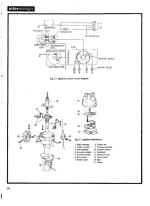 29
29 30
30 31
31 32
32 33
33 34
34 35
35 36
36 37
37 38
38 39
39 40
40 41
41 42
42 43
43 44
44 45
45 46
46 47
47 48
48 49
49 50
50 51
51 52
52 53
53 54
54 55
55 56
56 57
57 58
58 59
59 60
60 61
61 62
62 63
63 64
64 65
65 66
66 67
67 68
68 69
69 70
70 71
71 72
72 73
73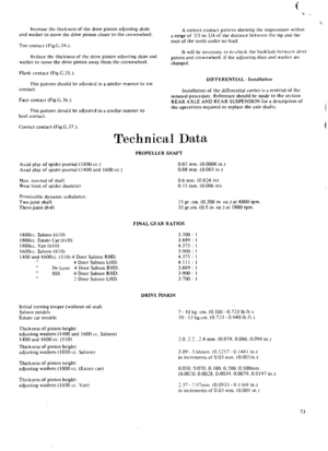 74
74 75
75 76
76 77
77 78
78 79
79 80
80 81
81 82
82 83
83 84
84 85
85 86
86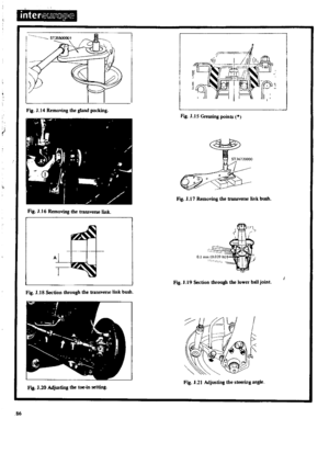 87
87 88
88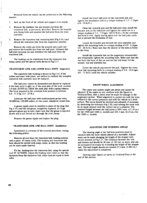 89
89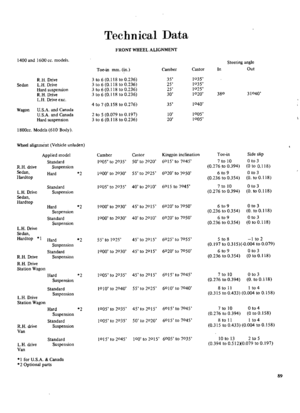 90
90 91
91 92
92 93
93 94
94 95
95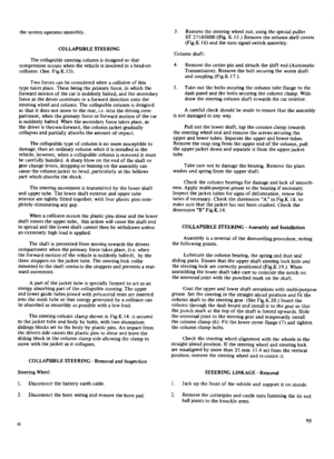 96
96 97
97 98
98 99
99 100
100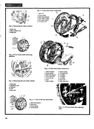 101
101 102
102 103
103 104
104 105
105 106
106 107
107 108
108 109
109 110
110 111
111 112
112 113
113 114
114 115
115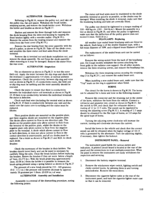 116
116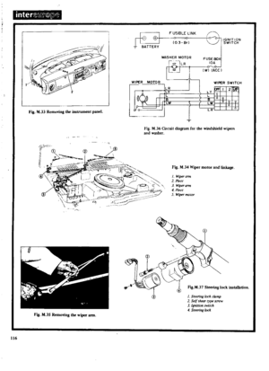 117
117 118
118 119
119 120
120 121
121 122
122 123
123 124
124 125
125 126
126 127
127 128
128 129
129 130
130 131
131 132
132 133
133 134
134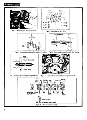 135
135 136
136 137
137 138
138 139
139 140
140 141
141 142
142 143
143 144
144 145
145 146
146 147
147 148
148 149
149 150
150 151
151 152
152 153
153 154
154 155
155 156
156 157
157 158
158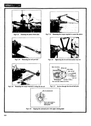 159
159 160
160 161
161 162
162 163
163 164
164 165
165 166
166 167
167 168
168 169
169 170
170


