Page 145 of 171

4
Cylinder
head
gasket
Cylinder
block
side
6
Oil
pump
5
Intake
manifold
Block
installing
surface
near
to
oil
exit
Control
valve
Angle
tube
connector
7
Rocker
cover
Tapping
screw
of
bume
plate
installing
SPECIFICATION
a
Valve
mechanism
Valve
clearance
cold
In
0
25
mm
0
0098
in
Ex
0
25
mm
0
0098
in
Hot
Reference
value
0
0098
in
In
0
28
mm
0
011
in
Ex
0
28
mm
0
011
in
Valve
head
diameter
In
42mm
1
654
in
Ex
35mm
1
378
in
Valve
stem
diameter
In
Ex
8mm
0
3150
in
Valve
length
In
116
4
mm
4
58
in
Ex
117
2
mm
4
61
in
Valve
lift
9
0mm
0
354
in
Valve
spring
free
length
Outer
42
5
mm
1
673
in
Inner
414mm
1
630
in
Valve
spring
loaded
length
Outer
29
0
mm
I
142
in
Inner
26
0
mm
1
024
in
Valve
spring
assembling
height
Outer
37
0mm
I
457
in
Inner
34
0
mm
1
339
in
Valve
spring
effective
wind
number
Outer
4
5mm
0
1772
in
Inner
6
25
mm
0
2461
in
Valve
spring
wire
diameter
Outer
4
2mm
0
1654
in
Inner
29mm
0
1142
in
Valve
spring
coil
diameter
Outer
27
5
mm
1
083
in
Inner
19
9mm
0
733
in
Valve
guide
length
In
48mm
1
890
in
Ex
60mm
2
362
in
Valve
guide
height
from
cylinder
head
In
Ex
16
7mm
0
657
in
Valve
guide
inner
diameter
In
Ex
7mm
0
2756
in
Valve
guide
outer
diameter
In
Ex
14
2mm
0
559
in
Valve
guide
to
stem
clearance
In
0
025
0
055
mm
0
0010
0
0022
in
Ex
0
04
0
077
mm
0
0016
0
0030
in
Valve
guide
interference
fit
In
Ex
0
040
0
069
mm
0
0016
0
0027
in
Max
tolerance
of
above
clearance
In
Ex
0
1
mm
0
0049
in
Valve
seat
width
In
Ex
2
05
2
33mm
0
0807
0
0917
in
Valve
seat
angle
In
Ex
900
b
Camshaft
and
timing
chain
Camshaft
end
play
0
07
0
148
mm
0
0028
0
0058
in
Cam
height
36
53
mm
1
438
in
Camshaft
journal
diameter
37
45
37
475
mm
1
474
1
475
in
S14
Page 146 of 171

Camshaft
bend
0
1
mm
0
0004
in
Camshaft
bearing
inner
diameter
375
37
525
mm
I476
I
477
in
0
025
0
075
mm
0
0008
0
0030
in
Camshaft
journal
to
bearing
clearance
c
Connecting
rod
Centre
distance
140mm
5
51
in
Big
end
play
0
110
0
246
mm
0
0043
0
0097
in
Connecting
rod
bearing
clearance
Connecting
rod
bend
0
05
mm
0
0020
in
0
03
0
06
mm
0
0012
0
0024
in
Connecting
rod
bearing
under
size
100
U
S
Bearing
thickness
Crank
pin
diameter
1483
1
499
mm
49
975
59
991
mm
0
0584
0
0590
in
1
967
1
968
in
1
609
1
622
mm
49
725
49741
mm
0
0633
0
0639
in
I
9576
1
9582
in
1734
1
747
mm
49
475
49491
mm
0
0683
0
688
in
1
9477
1
9483
in
1
857
1
872
mm
49
225
49
241
mm
0
0731
0
0737
in
1
938
1
939
in
1
984
I
997
mm
48
975
48
991
mm
0
081
0
0786
in
I
928
1
929
in
Bearing
size
S
T
D
25
U
S
50
U
S
75
U
S
d
Crankshaft
and
main
bearing
Wear
limit
of
ditto
clearance
Crank
pin
taper
and
out
of
round
Main
bearing
clearance
Less
than
0
01
mm
0
060
0
192
mm
0
0024
0
0008
in
0
3mm
Less
than
0
01
mm
0
03
0
06
mm
0
0012
0
0024
in
1
0mm
0
0004
in
Journal
taper
and
out
of
round
Crankshaft
free
end
play
0
0118
in
0
0004
in
Wear
limit
of
ditto
clearance
0
0039
in
Main
bearing
under
size
Bearing
size
Bearing
thickness
Crank
journal
diameter
100
U
S
2
485
2
505
mm
0
0978
0
0986
in
2
612
2
625
mm
0
1028
0
1033
in
2
737
2
750
mm
0
1078
0
1083
in
2
862
2
875
mm
0
1127
0
1132
in
2
987
3
000
mm
0
1176
0
1181
in
55
971
55
990
mm
2
2036
2
2043
in
55
721
55
740
mm
2
194
2
195
in
S
T
D
25
U
S
50
U
S
55
471
55
490
mm
2
184
2
185
in
55
221
55
240
mm
2
174
2
175
in
54
971
54
990
mm
2
164
2
165
in
75
U
S
SI5
Page 147 of 171

Crank
shaf
bend
Less
than
0
02
mm
0
0008
in
e
Piston
Pis
on
diameter
Ellipse
difference
Ring
groove
wid
h
84
968
85
0
mm
3
345
3
346
in
0
4
mm
0
01
7
in
Top
0
05
0
0020
0
0
03
mm
0
0787
0
001
in
Second
I
03
0
0012
2
0
0
01
mm
0
0787
0
0004
in
Oil
0
03
0
0012
4
0
0
01
mm
0
1575
0
0004
in
Piston
ring
side
clearance
0
035
0
55
mm
0
0014
0
0022
in
Top
0
04
0
08
mID
0
0016
0
0031
in
Second
0
02
0
06
mm
0
0008
0
0024
in
Oil
0
02
0
06
mm
0
0008
0
0024
in
Piston
to
bore
clearance
Ring
gap
Top
0
35
0
55
mm
0
0138
0
0217
in
Second
0
3
0
5
mm
0
0118
0
0197
in
Oil
0
35
0
55
mm
0
0138
0
0217
in
Top
0
01
0
0004
2
0
03
mm
0
0787
0
0012
in
Second
0
01
0
0004
2
0
03
mm
0
0787
0
0012
in
Oil
0
Q1
0
0004
4
0
03mm
0
I575
0
0012in
Ring
height
Piston
pin
interferenl
c
fit
of
piston
pin
to
piston
o
0
09
mm
0
0
0035
in
0
003
0
013
mm
0
0001
0
0005
in
Clearance
between
piston
pin
a
connecting
rod
bushing
Piston
pin
outer
diameter
21
991
22
0
mm
0
8658
0
8661
in
Connecting
rod
bushing
inner
diameter
21
995
22
008
mm
0
8659
0
8664
in
EMISSION
CONTROL
Crankcase
emission
con
trol
Closed
type
Exhaust
emiision
control
Nissan
Air
Injec
ion
System
Anti
backIrre
valve
Carburettor
Nihonkikaki
D3034C
Type
Model
Duration
time
Air
by
pass
DV54
1
3
L7
sec
at
500
Hg
9
7
in
Hg
Distribu
or
Hitachi
D423
Spark
plugs
BP
6E
Check
valve
Air
pump
Type
Opening
pressure
AMC
0
15
mAq
5
91
in
Aq
Model
Capacity
Pulley
ratio
ECP
20Q
IA
200
cc
rev
120
120
1
00
Cooling
fan
Type
No
of
blades
Spider
4
S16
Page 148 of 171

Fan
coupling
Pulley
ratio
fan
and
water
pump
Tuning
data
Basic
timing
Idling
speed
Distributor
dwell
angle
Spark
plug
gap
Choke
setting
CO
percent
setting
Fan
rpm
water
pump
rpm
3
300
4
000
120
103
Ll71
50
A
T
D
C
700
rpm
650
rpm
automatic
490
550
at
0
02
in
breaker
gap
0
8IJ
0
90
mm
0
03
I
5
0
0355
in
Manual
6
0
I
0
5
air
supply
hose
disconnected
Air
pump
drive
belt
tensioning
Permissible
slackness
of
8
0
12
0
mm
0
3
15
0
4
72
in
under
a
load
of7
1O
kg
1
54
2
20
lb
IGNITION
SYSTEM
DISTRIBUTOR
Type
Firing
order
Rotation
Igntion
timing
Without
emission
control
With
emission
control
Dwell
angle
Condenser
capacity
Advance
characteristics
D416
57
distributor
Hitachi
D416
57
Hitachi
D423
53
with
emission
control
system
134
2
Anti
clockwise
80
B
T
D
C
at
600
rpm
50
A
T
D
C
at
600
r
p
m
49
to
55
degreos
0
20
0
24
1
F
Centrifugal
Start
Maximum
degree
r
p
m
Vacuum
Start
Maximum
degree
r
p
m
Advance
characteristics
D423
53
distributor
Centrifugal
Start
Maximum
degree
r
p
m
Vacuum
Start
Maximum
degree
r
p
m
IGNITION
COIL
Type
Primary
voltage
Spark
gap
Primary
resistance
Secondary
resistance
SPARKING
PLUGS
Type
Gap
Fuel
Systenl
DESCRIPTION
FUEL
PUMP
Testing
FUEL
PUMP
Removing
and
Dismantling
CARBURETTOR
Idling
adjustment
FUEL
LEVEL
Adjusting
STARTING
INTERLOCK
VALVE
OPENING
THROTTLE
VALVE
INTERLOCK
OPENING
CARBURETIOR
Removing
and
Dismantling
DESCRIPTION
A
dual
barrel
down
draught
type
carburettor
is
fitted
to
vehicles
with
the
G
18
engine
A
Stromberg
type
D3034C
carburet
tor
is
installed
on
engines
with
exhaust
emission
controL
and
a
Solex
type
DAK340
carburettor
on
engines
not
equipped
with
this
type
of
system
Both
types
of
carburettors
incorporate
a
550
r
p
m
01
50
at
I
400
16
50
at
2
800
80
mmHg
6
50
at
200
r
p
m
475
r
p
m
01
50
at
1
000
23
50
at
2
600
80
mm
Hg
30
at
120
r
p
m
go
at
400
r
p
m
Hanshin
HM
12F
or
HP5
I
OE
with
emission
control
system
12
volts
more
than
6
mm
0
2362
in
3
8
ohms
at
200C
I
1
2
I
6
8
ohms
at
200
C
NGK
BP
6E
0
7
0
8
mm
0
028
0
031
in
or
0
80
9
mm
0
031
0
035
in
with
emission
control
system
primary
system
for
normal
running
and
a
secondary
system
for
full
load
running
a
float
assembly
which
supplies
fuel
to
both
primary
and
secondary
systems
a
starting
mechanism
and
accelerator
pump
which
provides
a
richer
mixture
on
accelera
tion
SI7
Page 149 of 171

1
D
1
1
I
i
l
I
1
j
j
w
n
I
UJ
1
j
e
tOll
i
j25z
t2JZ2
21
1
S
Mizin
nozzk
2
S
SmtzJJ
v
nturi
3
S
Main
air
bleed
4
S
Slow
jet
5
S
Slow
air
bleed
6
Needle
WIlve
7
Float
8
S
Emulsion
tube
9
S
Mainjd
10
S
Jly
paD
hol
11
S
Throttle
alve
12
Chob
I1tzhe
13
P
Main
air
bleed
14
P
Afuin
nozzle
15
Economizer
bleed
16
P
Slow
jet
17
Slow
onomiur
18
P
Slow
air
bleed
19
Airl
e
nt
20
Lnel
gauge
21
PMainjel
22
Idle
limitler
23
1dl
24
P
Jly
pa
hol
2S
P
Throttle
vahe
Fig
B
l
Sectional
view
of
the
DAK340
carburettor
Coil
Piiton
Strainer
v
cero
Fig
S
3
Electrical
fuel
pump
SI8
A
It
I
IL
o
l
Cfd
rj
1
l
o
j
11
111
r
J
l
l
b
I
1
1
F700
t
vahle
2
Vacuum
piJton
3
P
Slow
air
bleed
4
Slow
jtt
5
Slow
onomUt
T
6
P
Slow
air
bleM
7
Air
Fent
8
P
Main
air
bl
d
9
P
MiJin
nozzle
10
P
SmaU
venturi
1
J
Ozokt
valPe
12
Pumpnozzk
13
Pump
wd6h1
14
Discharft
check
valve
15
S
SnwU
venturi
17
S
Main
air
bleed
18
Step
air
bleed
19
Pump
arm
Fig
B
2
Sectional
view
of
the
D3034C
carburet
tor
fitted
to
engines
with
emiss
ion
control
5Y5tem
20
Step
jet
21
Pump
plunger
22
Inlet
c1r
k
l
aIve
23
S
Mizin
jet
24
lRtzp
uaun
25
lRtzplrragm
26
Step
port
27
Idle
port
28
P
T1vottk
valve
29
Idk
port
30
S
Dw
port
31
Idkadjust
screw
32
P
MiIin
jet
33
Po
NU
jet
34
Float
I
Ul
l
2
1
Fibre
mat
Nvlon
6
Fig
B
4
Fuel
strainer
Fig
Ii
s
Removing
the
fuel
pump
cover
1
Page 150 of 171

The
type
D3034C
carburettor
has
certain
additional
features
These
include
a
power
valve
mechanism
to
improve
the
performance
at
high
speed
a
fuel
cut
off
valve
which
cuts
the
fuel
supply
when
the
ignition
key
is
turned
to
the
off
position
and
an
idling
limiter
to
maintain
the
emissions
below
a
certain
level
Sectional
views
of
the
two
types
of
pumps
are
shown
in
Figs
8
1
and
B
2
An
EP
3
electrical
fuel
pump
is
located
in
the
centre
of
the
spare
wheel
housing
in
the
boot
Fig
B
3
shows
a
sectional
view
of
the
pump
with
its
contact
the
pump
mechanisms
solenoid
relay
and
built
in
filter
The
air
cleaner
uses
a
viscous
paper
type
element
which
should
be
replaced
every
40
000
km
24
000
miles
Cleaning
is
not
required
and
should
not
be
attempted
The
cartridge
type
fuel
strainer
incorporates
a
fibre
clement
which
should
be
renewed
at
inervals
not
exceeding
40
000
km
24
000
miles
Fit
B
4
shows
a
sectional
view
of
the
assembly
The
fuel
lines
should
not
be
disconnected
from
the
strainer
when
the
fuel
tank
is
full
unless
absolutely
necessary
as
the
strainer
is
below
the
fuel
level
FUEL
PUMP
Testing
Disconnect
the
fuel
hose
from
the
pump
outlet
Connect
a
hose
with
an
inner
diameter
of
approximately
6
mm
0
024
in
to
the
pump
outlet
and
place
a
container
under
the
end
of
the
pipe
Note
that
the
inner
diameter
of
the
pipe
must
not
be
too
small
or
the
pipe
will
be
incapable
of
delivering
the
correct
quantity
of
fuel
when
testing
Hold
the
end
of
the
hose
above
the
level
of
the
pump
and
operate
the
pump
for
more
than
IS
seconds
to
check
the
delivery
capacity
The
capacity
should
be
I
400
cc
3
24
U
S
pts
in
one
minute
or
less
The
pump
must
be
removed
from
the
vehicle
if
it
does
not
operate
or
if
a
reduced
quantity
of
fuel
flows
from
the
end
of
the
hose
Remove
the
pump
from
the
vehicle
and
test
as
follows
Connect
the
pump
to
a
fully
charged
battery
If
the
pump
now
operates
and
discharges
fuel
correctly
the
fault
does
not
lie
in
the
pump
but
may
be
attributed
to
any
of
the
following
causes
Battery
voltage
drop
poor
battery
earth
loose
wiring
loose
connections
blocked
hoses
or
a
faulty
carburettor
If
the
pump
does
not
operate
and
discharge
fuel
when
connected
to
the
battery
then
the
pump
itself
is
faulty
and
must
be
checked
as
follows
First
make
sure
that
current
is
flowing
This
will
be
indica
ted
by
sparking
at
the
tenninals
If
current
flows
the
trouble
is
caused
by
a
sticking
pump
plunger
or
piston
The
pump
must
be
dismantled
in
this
case
and
the
parts
thoroughly
cleaned
in
petrol
If
the
current
does
not
flow
a
coil
or
lead
wire
is
broken
and
the
pump
must
be
renewed
A
reduced
fuel
flow
is
caused
by
a
faulty
pump
inlet
or
discharged
valve
or
blocked
filter
mesh
The
pump
must
of
course
be
dismantled
and
serviced
as
necessary
FUEL
PUMP
Removing
and
Dismantling
Remove
the
bolts
attaching
the
fuel
pump
cover
to
the
floor
panel
see
Fig
B
S
Remove
the
bolts
attaching
the
pump
to
the
cover
2
Disconnect
the
cable
and
fuel
hoses
Withdraw
the
pump
Dismantle
as
follows
Slacken
the
locking
band
screws
and
remove
the
strainer
strainer
spring
filter
strainer
seal
and
locking
band
Remove
the
snap
ring
Withdraw
the
four
screws
from
the
yoke
and
remove
the
electromagnetic
ulJ
it
Press
the
plunger
down
and
withdraw
the
inlet
vaive
the
packing
and
the
cylinder
and
plunger
assembly
A
defective
eledrical
unit
cannot
be
dismantled
as
it
is
sealed
and
must
be
renewed
as
a
complete
unit
FUEL
PUMP
Inspection
and
Assembly
Wash
the
strainer
filter
and
gasket
in
petrol
and
dry
using
compressed
air
Renew
the
filter
and
gasket
if
necessary
Note
that
the
filter
should
be
cleaned
every
40
000
km
24
000
miles
Wash
the
plunger
piston
and
inlet
valve
in
petrol
and
make
sure
the
piston
moves
smoothly
in
the
cylinder
Replace
the
parts
if
found
to
be
defective
Insert
the
plunger
assembly
into
the
cylinder
of
the
electri
cal
unit
and
move
the
assembly
up
and
down
to
make
sure
tha
t
the
contacts
are
operated
If
the
contacts
do
not
operate
the
electrical
unit
is
faulty
and
must
be
renewed
Assembly
is
a
reversal
of
the
dismantling
procedures
tak
ing
care
to
renew
the
gaskets
as
necessary
CARBURETIOR
Idling
Adjustment
The
D3034C
carburettor
fitted
to
engines
equipped
with
an
emission
control
system
must
be
adjusted
as
described
under
the
heading
IGNITION
TIMING
AND
IDLING
SPEED
in
the
section
EMISSION
CONTROL
SYSTEM
Reference
should
be
made
to
carburettor
idling
adjustment
procedures
for
the
L14
L16
and
LI8
engines
when
adjusting
the
type
DAK
340
carburettor
fitted
to
the
G
18
engine
A
smooth
engine
speed
of
approximately
550
rpm
should
be
attained
in
this
case
FUEL
lEVEL
Adjustment
DAK
340earburettor
A
constant
fuellevcl
in
the
float
chamber
is
maintained
by
the
float
and
needle
valve
See
Fig
8
6
If
the
fuel
level
does
not
correspond
with
the
level
gauge
line
it
will
be
necessary
to
care
fully
bend
the
float
seat
until
the
float
upper
position
is
correctly
set
The
clearance
H
between
valve
stem
and
float
seat
should
be
I
5
mm
0
0059
in
with
the
float
fully
lifted
Adjustment
can
be
carried
out
by
carefully
bending
the
float
stopper
3
FUEL
lEVEL
Adjustment
D3034Ccarburettnr
The
fuel
level
should
correspond
with
the
level
gauge
line
Adjustment
can
be
carried
out
if
necessary
by
changing
the
gaskets
between
the
float
chamber
body
and
needle
valve
seat
The
gaskets
are
shown
as
item
4
in
Fig
B
7
When
correctly
adjusted
there
should
be
a
clearance
of
approximately
7
mm
0
027
in
between
float
and
chamber
as
indicated
STARTING
INTERLOCK
VALVE
OPENING
The
choke
valve
at
its
fully
closed
position
automatically
opens
the
throttle
valve
to
an
optimum
angle
of
14
degrees
on
the
type
DAK
340
carburettor
and
13
5
degrees
on
the
D3034C
carburettor
With
the
choke
valve
fully
closed
the
clearance
G
I
in
Fig
8
should
be
1
I
mm
0
0433
in
This
clearance
S19
Page 151 of 171
Onter
1
2
I
J
I
I
I
r
f
r
1
Float
SelllC
2
F10aI
3
Ffotzt
toppt
T
4
Nudk
m
1
F10at
2
Float
WJlve
ltat
3
Float
valJ1e
4
AcJiwtiflK
tpsket
5
Stopper
Fig
B
6
Adjusting
the
fuel
level
DAK340
C3tbutettor
Fig
B
7
Adjusting
the
fuel
level
D3034C
carburettor
1
11
J
Xi
I
tf
J
t
I
3
J
I
J
Th
1
Choke
mr
r
2
Otoke
m
LuL
3
Conn
ting
rod
4
Connectinlla
o
5
TIuottle
lever
Fig
B
S
Adjusting
the
starting
interlock
opening
6
O
1
Co1UJeCdrlK
lev
2
Rerum
plate
3
Adiust
pWe
4
17rrottle
clrzmber
5
Throttle
valve
1
S
Throttle
arm
2
S
Throttle
ntum
lever
3
Link
4
P1lIrortle
tml
5
P
1lIro
lle
valve
l
I
4
J
L
5
iF
l
1
L
Fig
B
9
Adjusting
the
throttle
valve
interlock
opening
OAK340
carburettor
Fig
B
lO
Adjusting
tbe
throttle
valve
interlock
opening
D3034C
carburettor
520
Page 152 of 171

between
primary
throttle
valve
and
the
wall
of
the
throttle
chamber
can
be
adjusted
if
necessary
by
carefully
bending
the
choke
connecting
rod
3
THROTILE
VALVE
INTERLOCK
OPENING
With
the
primary
throttle
valve
of
the
type
DAK340
carburettor
opened
to
600
as
shown
in
Fig
B
9
the
adjusting
plate
3
should
contact
the
connecting
lever
J
This
being
the
point
before
the
secondary
throttle
valve
is
brough
into
operation
The
linkage
between
primary
and
secondary
throttles
is
working
correctly
if
the
clearance
G
between
primary
throttle
valve
and
the
wall
of
the
chamber
is
738
mm
0
3937
in
Adjust
if
necessary
by
carefully
bending
the
adjusting
plate
at
point
A
until
the
correct
setting
is
obtained
With
the
primary
throttle
valve
of
the
type
D3034C
car
burettor
opened
at
an
angle
of
500
the
connecting
link
3
in
Fig
B
IO
should
ge
at
the
extreme
left
of
the
slot
in
the
throttle
ann
4
With
the
linkage
positioned
as
shown
measure
the
clearance
between
primary
throttle
valve
and
the
wall
of
the
chamber
as
described
for
the
DAK340
carburettor
Adjustment
can
be
made
if
necessary
by
bending
the
connecting
link
until
the
correct
clearance
is
obtained
CARBURElTOR
Removing
and
Dismantling
The
carburettor
can
be
removed
by
following
the
instruc
tions
previously
given
for
carburettor
removal
on
the
Ll4
L16
and
LIB
engines
Dismantle
the
type
DAK340
carburettor
as
follows
Remove
the
primary
throttle
return
spring
Take
off
the
E
ring
and
remove
the
pump
and
connecting
rod
Remove
the
split
pin
and
choke
connecting
rod
Remove
the
secondary
throttle
return
spring
Remove
the
choke
wire
arm
choke
valve
shaft
and
valve
spring
Take
off
the
clip
and
remove
the
choke
lever
and
spring
To
dismantle
the
float
chamber
take
off
the
diaphragm
cover
and
remove
the
spring
and
diaphragm
Remove
the
diaphragm
chamber
and
gasket
Take
off
the
float
chamber
cover
and
remove
the
gasket
level
gauge
rubber
seal
and
float
Remove
the
screw
from
the
filter
and
withdraw
the
nipple
and
filter
Remove
the
needle
valve
Take
off
the
cylinder
cover
and
pump
cover
and
withdraw
the
piston
piston
return
spring
and
inlet
valve
Remove
the
primary
main
air
bleed
the
secondary
main
air
bleed
and
emulsion
tube
Take
off
the
small
venturi
and
remove
the
primary
and
secondary
slow
jets
and
slow
air
bleeds
Remove
the
drain
plugs
and
take
out
the
primary
and
secondary
main
jets
To
dismantle
the
throttle
chamber
remove
the
throttle
adjusting
screw
and
spring
and
the
idling
adjusting
screw
and
spring
Withdraw
the
throttle
lever
spring
hanger
sleeve
connecting
lever
return
plate
and
adjusting
plate
Withdraw
the
primary
throttle
valve
and
primary
throttle
shaft
Withdraw
the
secondary
throttle
valve
and
secondary
throttle
shaft
The
type
D3034C
carburettor
can
be
dismantled
as
follows
Detach
the
starting
connecting
rod
from
the
choke
lever
and
accelerator
pump
connecting
rod
Remove
the
air
horn
pump
rod
slow
jets
the
primary
and
secondary
small
venturies
Detach
the
primary
and
secondary
linkages
Take
off
the
diaphragm
chambe
cover
and
take
out
the
spring
and
diaphragm
Remove
the
diaphragm
chamber
and
gasket
Separate
the
float
chamber
from
the
throttle
chamber
take
off
the
float
chamber
cover
and
remove
the
components
Remove
the
inlet
strainer
and
float
valve
seat
Remove
the
main
jets
and
take
off
the
fuel
cut
off
valve
CARBURETTOR
Assembly
and
Installation
The
assembly
and
installation
of
the
carburettor
is
a
reversal
of
the
dismantling
and
removal
procedures
Clean
and
inspect
all
components
as
described
for
the
carburettors
fitted
to
the
Ll4
Ll6
and
LI8
engines
TechnIcal
Data
CARBURETIOR
Small
ven
turi
First
7mm
8mm
Carburettor
Type
DAK340
Second
14mm
16mm
Main
jet
02
155
Primary
Secondary
Slow
jet
50
80
Main
air
bleed
60
80
Outlet
diameter
30mm
34mm
Emulsion
hole
0
5
mm
O
5mm
Venturi
diameter
23
mm
29
x
9
mm
Slow
air
bleed
Main
jet
119
165
First
160
Main
air
bleed
220
100
Second
150
220
Slow
jet
48
90
Slow
economizer
1
6
mm
dia
Slow
air
bleed
130
100
Power
jet
50
Slow
economizer
L4mm
Cushion
jet
120
Economizer
bleed
1
2mm
Air
jet
150
Carburettor
Type
D3034C
Power
system
Vacllum
acting
Vacuum
piston
diameter
9
0
mm
0
354
in
Primary
Secondary
Piston
spring
100
gr
0
220
Ibs
31
mm
1
22
in
Bore
30mm
34mm
Power
valve
spring
40
gr
0
0882
lbs
8
6mm
Large
venturi
23mm
28mm
0
34
in
52
 1
1 2
2 3
3 4
4 5
5 6
6 7
7 8
8 9
9 10
10 11
11 12
12 13
13 14
14 15
15 16
16 17
17 18
18 19
19 20
20 21
21 22
22 23
23 24
24 25
25 26
26 27
27 28
28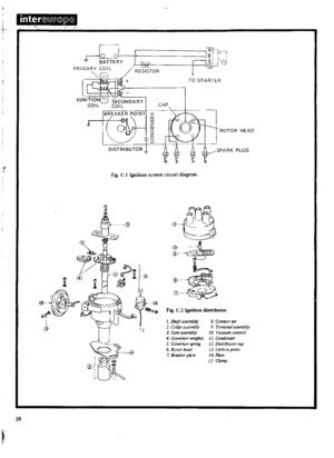 29
29 30
30 31
31 32
32 33
33 34
34 35
35 36
36 37
37 38
38 39
39 40
40 41
41 42
42 43
43 44
44 45
45 46
46 47
47 48
48 49
49 50
50 51
51 52
52 53
53 54
54 55
55 56
56 57
57 58
58 59
59 60
60 61
61 62
62 63
63 64
64 65
65 66
66 67
67 68
68 69
69 70
70 71
71 72
72 73
73 74
74 75
75 76
76 77
77 78
78 79
79 80
80 81
81 82
82 83
83 84
84 85
85 86
86 87
87 88
88 89
89 90
90 91
91 92
92 93
93 94
94 95
95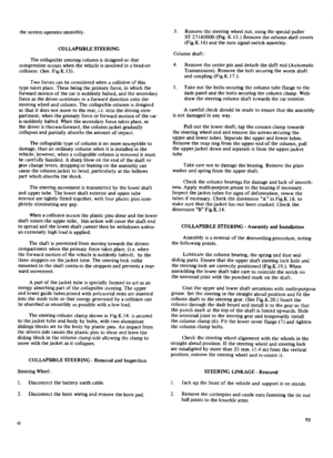 96
96 97
97 98
98 99
99 100
100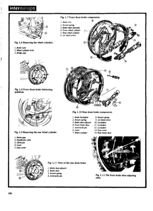 101
101 102
102 103
103 104
104 105
105 106
106 107
107 108
108 109
109 110
110 111
111 112
112 113
113 114
114 115
115 116
116 117
117 118
118 119
119 120
120 121
121 122
122 123
123 124
124 125
125 126
126 127
127 128
128 129
129 130
130 131
131 132
132 133
133 134
134 135
135 136
136 137
137 138
138 139
139 140
140 141
141 142
142 143
143 144
144 145
145 146
146 147
147 148
148 149
149 150
150 151
151 152
152 153
153 154
154 155
155 156
156 157
157 158
158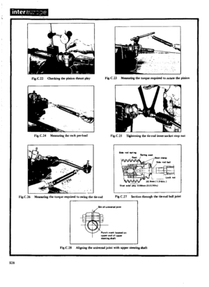 159
159 160
160 161
161 162
162 163
163 164
164 165
165 166
166 167
167 168
168 169
169 170
170