Page 105 of 171
inter
f
illl
@
l
l
Au
y
l
ver
I
R
H
I
Equaliler
b2nd
i
b7ke
Pl
te
Iock
band
buk
able
I
I
I
T
@A
Adjuster
cable
oo
pm
Odb
k
SPd
wm
LH
able
C
Note
@
Apply
bearing
grease
@APPIYch
S
i
Pin
fulcrum
hand
brab
lever
6c
1l
Clip
cable
frout
N
nd
brake
Fill
L21
Handbrake
linkage
1400
and
1600
c
c
Saloons
1
I
J
Pull
priDg
1
Clt
vU
Balance
leve
I
I
J
c
1
1
I
I
1
l
J
L
I
iL
Note
@
Apply
engine
oil
8
S
J
@
I
Aj
Fran
able
Rear
cable
L
I
r
f
7
n
t
i
Adjust
position
A
Fig
L
22
Handbrake
linkage
1400
and
1600
c
c
Estate
cars
1
Control
sUm
2
Control
ratchet
Xing
3
O
mtrol
ratchet
4
O
mtro
guide
5
Control
bracket
6
OJntrol
yoke
7
wer
spring
8
Control
lever
Fig
L
23
Handbrake
linkage
1800
c
c
models
104
able
s
Fig
L
19
Checking
the
brake
disc
for
run
out
1
j
v
fti
r
v
r
Fig
L
20
As
embling
the
piston
seals
and
retainer
ti
J
4
Fill
L
24
The
handbrake
cable
adjuster
Saloons
9
Front
cable
10
Centre
lever
II
Rear
cable
adjuster
12
DIble
lock
plate
13
Return
spring
14
RI
fU
cabk
15
Qevis
Page 106 of 171

HAND
BRAKE
Removal
The
mechanical
handbrake
linkages
are
shown
in
Figs
L
21
1
22
and
1
23
1400
and
1600cc
models
Front
cable
Release
the
hand
brake
and
disconnect
the
front
cable
by
removing
the
clevis
pin
from
the
lever
Unscrew
the
adjusting
nut
from
the
rear
of
the
front
cable
Fig
L
24
Remove
the
cable
from
the
hand
brake
lever
Remove
the
clamp
holding
the
cable
to
the
under
body
Pull
out
the
lock
plate
holding
the
front
cable
to
the
retainer
and
completely
withdraw
the
cable
Withdraw
the
cable
by
unfastening
the
outer
casing
which
is
pressed
into
the
handbrake
control
bracket
Handbrake
lever
Fig
1
25
Remove
the
clevis
pin
connecting
the
lever
yoke
and
lever
Remove
the
clevis
pin
connecting
the
control
guide
and
the
control
bracket
Lift
out
the
handbrake
assembly
Rear
cable
Saloons
Remove
the
adjusting
nut
from
the
adjuster
Fig
L
26
and
disconnect
the
left
hand
rear
cable
from
the
handbrake
adjuster
Pull
out
the
lock
plates
and
remove
the
clevis
pin
connecting
the
cables
to
the
levers
of
the
rear
wheel
cylinders
Rear
cable
Estate
car
and
rigid
axle
saloon
Remove
the
clevis
pin
from
both
ends
of
the
rear
cable
Remove
the
connecting
rods
by
extracting
the
puU
off
springs
and
clevis
pins
1800cc
models
Handbrake
lever
Disconnect
the
terminal
from
the
hand
brake
warning
switch
Remove
the
nuts
securing
the
control
bracket
to
the
dashboard
Pull
out
the
lock
pin
and
cotter
pin
and
withdraw
the
handbrake
lever
assembly
Front
cable
Remove
the
return
spring
and
loosen
the
adjuster
10cknuL
Detach
the
front
cable
from
the
handbrake
lever
Remove
the
nuts
securing
the
cable
to
the
dashboard
Fig
L
27
and
with
draw
the
cable
towards
the
engine
Rear
cable
Saloon
Disconnect
the
cable
at
the
adjuster
and
detach
the
return
spring
from
the
centre
lever
See
Fig
L
28
Remove
the
cable
lock
plates
from
the
rear
suspension
Remove
the
clevis
pin
attaching
the
cable
at
the
rear
wheel
cylinder
Rear
cable
Estate
car
and
Van
Unfasten
the
pull
spring
and
remove
the
clevis
pins
at
the
balance
lever
and
wheel
sides
Fig
L
29
Detach
the
connecting
rod
Remove
the
nut
securing
the
connecting
rod
balance
lever
and
the
lever
from
the
rear
axle
housing
HANDBRAKE
Installation
Check
the
cables
for
signs
of
deterioration
fraying
etc
Examine
the
handbrake
lever
and
ratchet
for
wear
and
renew
as
necessry
Check
the
springs
for
evidence
of
weakness
and
make
sure
that
the
balance
lever
and
bushes
are
satisfactory
Installation
is
a
reversal
of
the
removal
procedure
Make
sure
that
all
sliding
parts
are
greased
Adjust
the
hand
brake
in
the
following
manner
Release
the
hand
brake
and
adjust
the
rear
brake
shoes
as
previously
described
The
1400
and
1600cc
Saloon
handbrake
is
adjusted
to
give
a
lever
stroke
of
85
95mm
3
34
3
74
in
by
setting
the
adjusting
nuts
Fig
L
24
The
lever
stroke
on
the
estate
car
should
be
adjusted
to
50
75mm
2
0
3
0
in
by
turning
the
adjuster
shown
in
Fig
L
30
Adjust
the
1800cc
models
to
give
a
handbrake
lever
stroke
of
90
100
mm
3
5
3
9in
by
turning
the
adjuster
2
in
Fig
L
28
Retighten
the
locknut
after
adjusting
BLEEDING
THE
HYDRAULIC
SYSTEM
The
hydraulic
system
must
be
bled
if
the
circuit
has
been
opened
at
any
point
or
if
the
level
of
the
fluid
in
the
master
cylinder
reservoir
has
fallen
too
low
allowing
air
to
enter
the
system
Bleeding
is
usually
a
two
man
operation
as
assistance
will
be
required
to
work
the
brake
pedal
The
master
cylinder
reservoir
must
be
topped
up
constantly
throughout
the
operation
whilst
a
check
is
carried
out
on
the
fluid
expelled
Bleeding
should
be
carried
out
at
the
master
cylinder
nrst
then
from
the
brake
furthest
away
from
the
master
cylinder
and
working
round
finally
to
the
brake
nearest
to
the
master
cylinder
Bleeding
should
therefore
be
carried
out
in
the
follow
ing
order
Rear
left
wheel
rear
right
wheel
front
left
wheel
front
right
wheel
Oean
the
area
round
the
master
cylinder
cover
take
off
the
cover
and
top
up
the
reservoir
if
necessary
Clean
the
rele
vant
air
bleed
screw
and
take
off
the
cap
Attach
a
suitable
hose
to
the
bleed
screw
and
place
the
free
end
of
the
hose
in
a
glass
jar
containing
brake
fluid
Open
the
bleed
screw
and
depress
the
brake
pedal
to
allow
the
fluid
to
enter
the
glass
container
Tighten
the
bleed
screw
when
the
pedal
is
fully
depressed
and
allow
the
pedal
to
return
Repeat
the
procedure
until
the
fluid
is
completely
free
from
air
bubbles
then
carry
out
the
same
operation
on
the
other
three
wheels
Top
up
the
fluid
in
the
reservoir
to
the
correct
level
but
do
not
re
use
the
fluid
previously
withdrawn
from
the
system
105
Page 107 of 171
inter
jjiC@
V
6iIiIIlli
I
Ii
r
f
r
7
r
Y
t
I
10
1
L
u
N
c
I
F
ll
L
2S
The
handbrake
mbly
Fig
L
27
Front
handbrake
cable
attachment
nuts
e7
rl
A
I
r
I
r
J
i
I
f
I
I
I
of
II
J
F
F
ll
L29
Balance
lever
Estate
ClU1l
and
Vans
F
ll
L
30
AdjWltins
the
handbrake
cable
Estate
ClU1l
106
J
ei
Fig
L
26
Removing
the
lock
plates
see
text
I
7
I
i
1
@
i
1
0
1
e
V
O
V
I
r
r
if1
1i
cl
t
Ji
Y
a
t
3
F
ll
L
28
Rear
cable
layout
1800
C
c
SatOOWl
ok
pedat
height
H
87
mm
7
362
in
202
mm
7
953
ill
Jltznual
transmission
AutomItic
transmission
y
Brake
pedal
full
stroke
L
141
0149
mm
5
55
to
5
86
in
Brake
pedal
p
tJv
P
5
to
15
mm
0
2
to
0
6
ilL
Fig
L
31
Brake
pedal
adjWltment
1400
and
1600
c
c
models
l
car
Ll
1
f
1
J
111
I
l
j
u
n
l
71
t
i1
Unit
mfll
in
1
Push
rod
adjusting
scrt
W
2
Ptdlz
stop
3
Brake
Iilmp
switch
4
Clevis
pin
Fig
L
32
Brake
pedaladjWltment
800
c
c
models
Page 108 of 171

BRAKE
PEDAL
ADJUSTMENT
The
brake
pedal
height
and
free
play
can
be
adjusted
in
the
following
manner
1400
and
1600
CC
models
Adjust
the
length
of
the
master
cylinder
push
rod
until
the
height
of
the
pedal
pad
is
187
mm
7
36
in
for
manual
gear
boxes
and
202
mm
7
95in
for
automatic
transmission
vehicles
without
brake
light
switch
Fig
L
31
Retighten
the
locknut
Screw
in
the
brake
light
switch
until
the
screwed
part
of
the
switch
is
against
the
front
of
the
stopper
bracket
then
tighten
the
locknut
Screw
in
the
stopper
bolt
until
the
moveable
part
of
the
switch
is
completely
pushed
in
by
the
pedal
and
tighten
the
locknut
in
this
position
Make
sure
that
the
lamp
is
00
when
the
pedal
is
pushed
down
by
1
5mm
0
06
in
1800cc
models
Adjust
the
bolt
of
the
brake
lamp
switch
until
its
end
face
is
flush
with
the
locknut
then
tighten
the
locknut
securely
See
Fig
L
32
Adjust
the
pedal
stopper
until
the
pedal
pad
is
positioned
at
a
height
of
185
mrn
7
28
in
from
the
floor
then
tighten
the
stopper
with
the
locknut
Adjust
the
length
of
the
master
cylinder
push
rod
until
a
pedal
free
play
of
I
5mm
0
04
D
2in
is
obtained
then
retighten
the
locknut
Depress
the
brake
pedal
several
times
to
make
sure
that
a
full
travel
of
145mm
5
7
in
is
available
and
that
the
pedal
moves
freely
and
without
noise
Technical
Data
BRAKE
PEDAL
Pedal
height
1400
and
1600cc
models
I
87mm
7
362in
manual
gearbox
202mm
7
953in
auto
matic
185mm
7
28in
145mm
5
71
in
1800cc
models
Full
stroke
MASTER
CYUNDER
Inner
diameter
Piston
running
clearance
19
05mm
0
75
in
0
15mm
0
006
in
WHEEL
BRAKE
CYLINDERS
Inner
diameter
1400
and
1600cc
Front
drum
Front
disc
Rear
with
front
drum
Rear
with
front
disc
22
22mm
7
8in
50
8mm
2
0
in
22
22mm
7
8in
20
64mm
13
16
in
Inner
diameter
I
BOOcc
Front
drum
20
6mm
13
16in
Front
disc
Rear
50
8mm
2
0in
22
2mm
7
8
in
BRAKE
DRUM
AND
BRAKE
DISC
Drum
inner
diameter
Drum
outer
diameter
Out
of
round
maximum
Repair
limit
of
drum
Maximum
disc
run
out
Repair
limit
of
disc
228
6mm
9
0in
232mm
9
13in
0
05mm
0
002
in
230mm
9
055
in
0
06mm
0
0024
in
8
4mm
0
331
in
BRAKE
UNINGS
Drum
brakes
Width
x
thickness
x
length
40
x
4
5
x
219
5mm
1
575
x
1
772
x
8
642in
Disc
brakes
39
7
x
9
x
86mm
1
563
x
0
354
x
3
386in
Total
braking
area
Front
drum
brake
Front
disc
brake
Rear
351
sq
cn
54
4
sq
in
114
2
sq
cm
17
7
sq
in
351
sq
cm
54
4
sq
in
107
Page 109 of 171
interQ
8
j
@W
2
m
tV
r
ReJld
cop
level
th
elk
FIg
M
I
llIecking
the
specific
gra
ity
of
the
battery
electrolyte
I
Thermal
u
e
Hydrometer
f
j
0
l
Q
I
iJ
Qy@
I
@
@
@
ti
II
@
@
Fig
M
3
Brush
cover
removed
j
i
Fill
M
2
Starter
motor
components
1
L
u
uJIner
pin
2
Drive
mil
Nack
t
3
Dult
COPD
4
E
mmtle
r
5
Aut
mzl
6
Solmoid
mlch
7
Arm
zturr
8
Thnut
9
IJriv
mil
blllck
t
bush
10
17uust
WdSMr
11
Stop
washer
12
CiTc
ip
13
PirUon
srap
collar
14
Pinion
IS
IWfni1l6
clutch
16
Field
coil
17
Yok
18
Politive
brwh
19
N
J1iP
bnuh
20
Bnuh
rprinK
21
Brullr
holder
22
Bearing
bwh
23
Rmr
COJIU
24
Through
botrr
@
FIg
M
5
Yoke
assembly
removed
Fill
M
4
Solenoid
switch
1
108
Fig
M
6
Annatore
assembly
and
engagemenr
lever
removed
Page 110 of 171

ElectrIcal
EquIpment
DESCRIPTION
BATTERY
Maintenance
STARTER
MOTOR
Removal
and
Dismantling
STARTER
MOTOR
Testing
STARTER
MOTOR
Assembly
and
Installation
ALTERNATOR
Removal
Dismantling
and
Inspection
DESCRIPTION
A
12
volt
negative
earth
electrical
system
is
used
in
which
the
battery
is
charged
by
an
alternator
In
the
alternator
a
magnetic
field
is
produced
by
the
rotor
which
consists
of
the
alternator
shaft
field
coil
p
le
pieces
and
slip
rings
Output
current
is
generated
in
the
armature
coils
located
in
the
stator
Six
silicon
diodes
are
incorporated
in
the
alternator
caSing
to
rectify
the
alternating
current
supply
A
voltage
regulator
and
pilot
lamp
relay
are
built
in
the
regulator
box
which
nonnally
does
not
give
trouble
or
require
attention
The
starter
motor
is
a
brush
type
series
wound
motor
in
which
positive
meshing
of
the
pinion
and
ring
gear
teeth
are
secured
by
means
of
an
overrunning
clutch
BATTERY
Maintenance
The
battery
should
be
maintained
in
a
clean
and
dry
condition
at
all
times
or
a
current
leakage
may
occur
between
the
terminals
If
frequent
topping
up
is
required
it
is
an
indication
of
overcharging
or
deterioration
of
the
battery
When
refitting
the
cables
clean
them
thoroughly
and
coat
their
terminals
and
the
terminal
posts
with
petroleum
jelly
Check
the
level
of
the
electrolyte
in
the
battery
at
frequent
intervals
and
top
up
if
necessary
to
the
level
mark
on
the
battery
case
with
distilled
water
A
hydrometer
test
should
be
carried
out
to
determine
the
state
of
charge
of
the
battery
by
measuring
the
specific
gravity
of
the
electrolyte
It
should
be
pointed
out
that
the
addition
of
sulphuric
acid
will
not
normally
be
necessary
and
should
only
be
carried
out
by
an
expert
when
required
The
specific
gravity
of
the
electrolyte
should
be
ascertained
with
the
battery
fully
charged
at
an
electrolyte
temperature
of
200C
680F
The
specific
gravity
of
the
electrolyte
decreases
or
increases
by
0
0007
when
its
temperature
rises
or
falls
by
10C
1
80F
respectively
The
temperature
referred
to
is
that
of
the
electrolyte
and
not
the
ambient
temperature
to
correct
a
reading
for
an
air
temperature
it
will
be
necessary
to
add
0
0035
to
the
reading
for
every
50C
above
200C
Conversely
0
0035
must
be
deducted
for
every
SOC
below
200C
Test
each
cell
separately
and
draw
the
liquid
into
the
hydrometer
several
times
if
a
built
in
thermometer
type
is
used
The
correct
specific
gravity
readings
should
be
as
follows
ALTERNATOR
Assembly
and
Installation
HEAD
LAMPS
Replacing
HORN
INSTRUMENT
PANEL
Removal
WINDSCREEN
WIPERS
WINDSCREEN
WASHERS
IGNITION
SWITCH
AND
STEERING
LOCK
Cold
climates
Temperature
climates
Tropical
climates
Permissible
value
Over
1
22
Over
1
20
Over
1
18
Fully
charged
at
200C
680F
1
28
1
26
1
23
The
battery
should
be
recharged
if
a
low
specific
gravity
reading
is
indicated
Always
disconnect
both
terminals
of
the
battery
when
charging
and
clean
the
terminal
posts
with
a
soda
solution
Remove
the
vent
plugs
and
keep
the
electrolyte
temperature
below
450C
l130F
during
charging
Check
the
specific
gravity
after
charging
and
if
it
is
above
1
260
at
200C
680C
add
distilled
water
STARTER
MOTOR
Removal
and
Dismantling
As
previously
stated
the
starter
motor
is
brush
type
series
wound
motor
in
which
the
positive
meshing
of
the
pinion
and
ring
gear
teeth
are
secured
by
an
overrunning
clutch
The
over
running
clutch
employs
a
shift
lever
to
slide
the
pinion
into
mesh
with
the
flywheel
ring
gear
teeth
when
the
starter
is
operated
When
the
engine
starts
the
pL
lion
is
permitted
to
overrun
the
clutch
and
armature
but
is
held
in
mesh
until
the
shift
lever
is
released
An
exploded
view
of
the
starter
is
shown
in
Fig
M
2
To
remove
the
starter
motor
proceed
as
follows
Disconnect
the
battery
earth
cable
2
Disconnect
the
black
and
yellow
wire
from
the
solenoid
terminal
and
the
black
cable
from
the
battery
terminal
3
Remove
the
two
bolts
securing
the
starter
motor
to
the
clutch
housing
Pull
the
starter
motor
assembly
forwards
and
withdraw
it
from
the
v
hicle
To
dismantle
the
starter
motor
ftrst
remove
the
brush
cover
and
lift
out
the
brushes
as
shown
in
Fig
M
3
Loosen
the
nut
securing
the
connecting
plate
to
the
solenoid
M
terminal
Remove
the
solenoid
retaining
screws
take
out
the
cotter
pin
and
withdraw
the
shift
lever
pin
Remove
the
solenoid
assembly
as
shown
in
Fig
M
4
Remove
the
two
through
bolts
and
rear
cover
assembly
then
remove
the
yoke
assembly
by
lightly
tapping
it
with
a
wooden
mallet
Fig
M
S
Withdraw
the
armature
and
shift
lever
Fig
M
6
Remove
the
pinion
stopper
from
the
armature
shaft
by
removing
the
stopper
washer
pushing
the
109
Page 111 of 171
inter
r
0J
@
jll@
FIg
M
7
Over
unning
clutch
assembly
1
m
ILE
COMMUTATOR
0
5
to
0
8
mrtl
ROUND
O
0197
to
0
0315
nl
SEGMENT
MICA
CORRECr
INCORRECT
Fig
M
9
Undercutting
the
commutator
insulation
Fig
M
11
Testing
the
field
coils
for
continuity
5
y
SERIES
COIL
5
r
SHUNT
COIL
Fig
M
13
Testing
the
solenoid
witch
10
J
Fig
M
8
Checking
the
brush
pring
tension
Fig
M
lO
Checking
the
armature
shaft
for
run
out
J
I
I
J
I
L
j
J
j
Fig
M
12
Testing
the
field
coils
for
earthing
1
rl
wr
v
E
L
DIMENSION
131
7
to
32
3mm
1
248
to
1
272
in
I
Adjus
llUt
2
PluJlKeradjuster
F
8
M
14
Measuring
the
gap
between
pinion
and
pinion
stop
I
Page 112 of 171

stopper
to
the
overrunning
clutch
side
and
removing
the
stopper
clip
Remove
the
stopper
and
overrunning
clutch
as
shown
inFig
M
7
Oean
the
dismantled
components
and
check
them
for
wear
or
damage
Cbeck
the
brushes
and
renew
them
if
worn
below
6
5mm
0
257
in
Fit
new
brushes
if
the
brush
contact
is
loose
Cbeck
the
brush
holders
and
spring
clips
and
make
sure
that
they
are
not
bent
or
distorted
The
brushes
should
move
freely
in
their
housings
and
can
be
eased
with
a
file
if
necessary
The
brush
spring
tension
should
be
approximately
0
8kg
1
76Ib
and
can
be
checked
with
a
spring
balance
as
shown
in
Fig
M
S
Armature
assembly
Make
sure
that
the
surface
of
the
commutator
is
not
rough
or
pitted
Oean
and
lightly
polish
with
a
No
500
emery
cloth
if
necessary
If
the
commutator
is
badly
worn
or
pitted
it
should
be
skimmed
in
a
lathe
only
a
light
cut
must
be
taken
to
remove
the
minimum
amount
of
metal
If
the
commutator
diameter
wear
limit
of
0
2mm
0
OS
in
is
exceeded
the
assembly
must
be
renewed
Undercut
the
mica
between
the
commutator
segments
when
the
depth
of
mica
from
the
surface
of
the
segment
is
less
than
0
2mm
0
08
in
The
depth
should
be
between
0
5
0
8mm
0
0197
0
0315
in
as
shown
in
Fig
M
9
The
armature
shaft
should
be
checked
for
straightness
by
mounting
between
the
centres
of
lathe
and
positioning
a
dial
gauge
as
shown
in
Fig
M
I
O
Renew
the
armature
if
the
bend
of
the
shaft
exceeds
0
08mm
0
0031
in
Field
coils
testing
Test
the
field
coils
for
continuity
by
connecting
a
circuit
tester
between
the
positive
terminal
of
the
field
coil
and
the
positive
terminal
of
the
brush
holder
as
shown
in
Fig
M
I
I
If
a
reading
is
not
obtained
the
field
circuit
or
coil
is
open
Cbnnect
the
tester
to
the
yoke
and
field
coil
positive
teoninal
as
shown
in
Fig
M
12
to
check
the
field
coils
for
earthing
Unsolder
the
connected
part
of
each
coil
and
check
the
circuit
for
earthing
in
a
similar
manner
Renew
the
field
coils
if
they
are
open
earthed
or
short
circuited
Outch
assembly
The
overrunning
clutch
must
be
replaced
if
it
is
slipping
or
dragging
Examine
the
pinion
and
sleeve
making
sure
that
the
sleeve
is
able
to
slide
freely
along
the
armature
shaft
spline
Inspect
the
pinion
teeth
for
signs
of
rubbing
and
check
the
fly
wheel
ring
gear
for
damage
or
wear
Bearings
Inspect
the
metal
bearing
bushes
for
wear
and
side
play
The
bushes
must
be
renewed
if
the
clearance
between
the
bearing
bush
and
armature
shaft
is
in
excess
of
0
02mm
0
008
in
New
bearing
bushes
must
be
pressed
in
so
that
they
are
flush
with
the
end
of
the
case
and
reamed
ou
t
to
give
a
clearance
of
0
03
0
10
mm
0
0012
0
0039
in
H
Solenoid
assembly
Inspect
the
solenoid
contact
surface
and
replace
if
showing
signs
of
wear
or
roughness
Replace
the
pinion
sleeve
spring
if
weakened
Check
the
series
coil
by
connecting
an
8
12
volt
supply
between
the
Sand
M
terminals
as
shown
in
Fig
M
13
The
series
coil
is
normal
if
the
plunger
operates
Test
the
shunt
coil
by
connecting
the
S
terminal
the
M
terminal
and
the
solenoid
body
as
shown
in
the
lower
illustration
of
Fig
M
13
Open
the
M
terminal
when
the
plunger
is
operated
the
shunt
coil
is
satisfactory
if
the
plunger
stays
in
the
operated
position
Measure
the
length
L
between
theylonger
adjusting
nut
and
solenoid
cover
Press
the
plunger
against
a
firm
surface
as
shown
in
Fig
M
14
and
check
that
the
dimension
is
within
the
figures
given
Turn
the
adjusting
nut
if
necessary
until
the
required
dimension
is
obtained
STARTER
MOTOR
Assembly
and
Installation
The
assembly
and
installation
procedures
are
a
reversal
of
the
removal
and
dismantling
operations
When
assembling
the
starter
smear
the
armature
shaft
spline
with
grease
and
lightly
oil
the
bearing
bushes
and
pinion
ALTERNATOR
The
alternator
is
driven
by
the
fan
belt
and
has
an
advant
age
over
a
dynamo
in
that
it
provides
current
at
low
engine
speeds
thereby
avoiding
battery
drain
Maintenance
is
not
normally
required
but
the
tension
of
the
fan
belt
should
be
checked
and
adjusted
if
necessary
as
described
in
the
section
COOLING
SYSTEM
Care
must
be
taken
not
to
overtighten
the
fan
belt
or
the
alternator
bearings
will
be
overloaded
The
alternator
output
can
be
checked
with
the
alternator
in
the
vehicle
by
carrying
out
the
following
test
Ensure
that
the
battery
is
fully
charged
Withdraw
the
connectors
from
the
alternator
F
and
N
terminals
and
connect
a
jumper
lead
between
the
F
and
A
terminals
Connect
a
voltmeter
to
the
E
and
A
alternator
terminals
with
the
negative
lead
to
terminal
E
and
the
positive
lead
to
the
terminal
A
as
shown
in
Fig
M
IS
Switch
the
headlamps
on
to
full
beam
and
start
the
engine
Increase
the
engine
speed
gradually
and
note
the
reading
on
the
voltmeter
when
the
engine
reaches
a
speed
of
approximately
lOaD
rpm
The
alternator
is
operating
satisfactorily
if
the
voltmeter
shows
a
reading
above
12
5
volts
If
the
reading
is
below
12
5
volts
the
alternator
is
defective
and
should
be
removed
for
inspection
ALTERNATOR
Removal
Disconnect
the
negative
lead
from
the
battery
and
the
two
lead
wires
and
connector
from
the
alternator
Slacken
the
alter
nator
mounting
bolts
and
take
off
the
fan
belt
Take
out
the
mounting
bolts
and
withdraw
the
alternator
from
the
vehicle
III
 1
1 2
2 3
3 4
4 5
5 6
6 7
7 8
8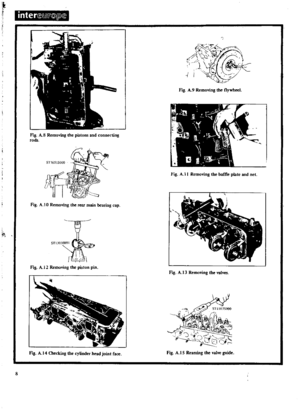 9
9 10
10 11
11 12
12 13
13 14
14 15
15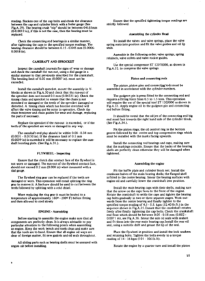 16
16 17
17 18
18 19
19 20
20 21
21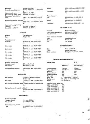 22
22 23
23 24
24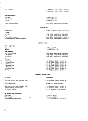 25
25 26
26 27
27 28
28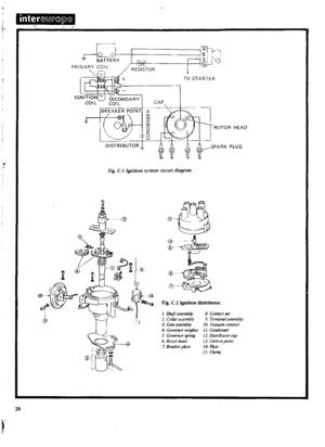 29
29 30
30 31
31 32
32 33
33 34
34 35
35 36
36 37
37 38
38 39
39 40
40 41
41 42
42 43
43 44
44 45
45 46
46 47
47 48
48 49
49 50
50 51
51 52
52 53
53 54
54 55
55 56
56 57
57 58
58 59
59 60
60 61
61 62
62 63
63 64
64 65
65 66
66 67
67 68
68 69
69 70
70 71
71 72
72 73
73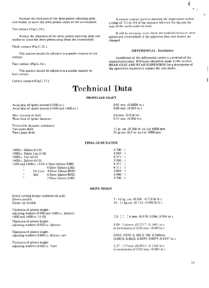 74
74 75
75 76
76 77
77 78
78 79
79 80
80 81
81 82
82 83
83 84
84 85
85 86
86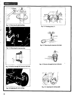 87
87 88
88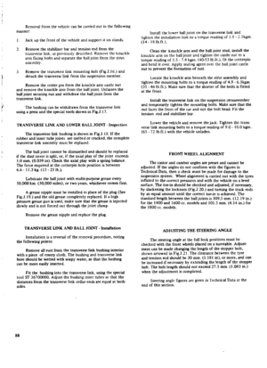 89
89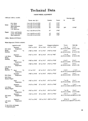 90
90 91
91 92
92 93
93 94
94 95
95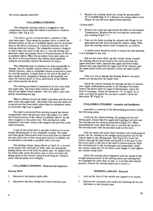 96
96 97
97 98
98 99
99 100
100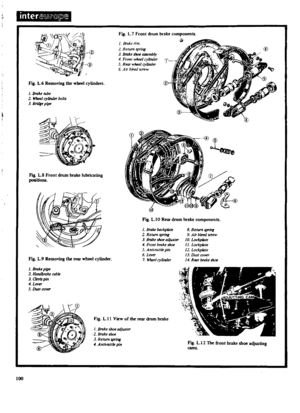 101
101 102
102 103
103 104
104 105
105 106
106 107
107 108
108 109
109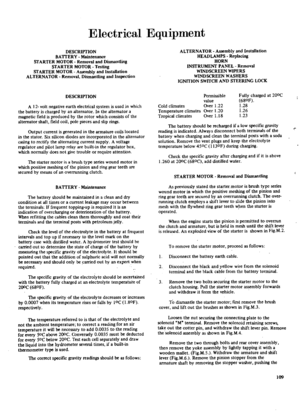 110
110 111
111 112
112 113
113 114
114 115
115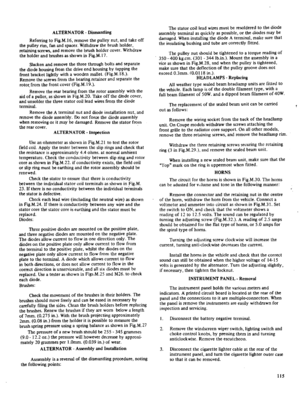 116
116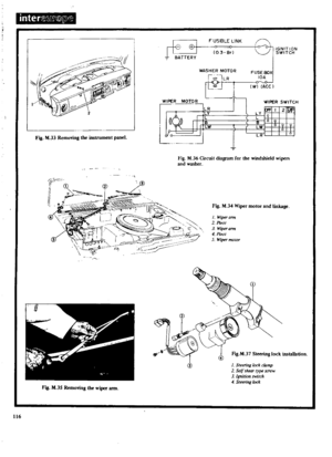 117
117 118
118 119
119 120
120 121
121 122
122 123
123 124
124 125
125 126
126 127
127 128
128 129
129 130
130 131
131 132
132 133
133 134
134 135
135 136
136 137
137 138
138 139
139 140
140 141
141 142
142 143
143 144
144 145
145 146
146 147
147 148
148 149
149 150
150 151
151 152
152 153
153 154
154 155
155 156
156 157
157 158
158 159
159 160
160 161
161 162
162 163
163 164
164 165
165 166
166 167
167 168
168 169
169 170
170


