Page 97 of 171
I
Fig
K
16
Removing
the
column
sheD
covers
inter
i
mj
rD
1
f
1
A
iJI1i
j
j
r
I
I
s
Ii
i
FIg
K
15
Removing
the
steering
wheel
Fig
K
l7
Removing
the
rubber
coupling
securing
bolt
1
bclttt
ube
2
Column
clamp
Fig
K
19
Steering
lock
installation
Fig
K
18
The
standard
dimension
between
coluDDl
clamp
and
lower
jacket
J
A
6
c
V
1
Rubbt
r
coupling
2
Steen
column
3
Worm
1
4
Dash
ptmd
5
ColUmrl
3hDf
6
Colli
clamp
7
Lowt
r
jacket
flangt
FIg
K
20
Installing
tbe
steering
column
assembly
96
f
ftb
Fig
K
21
The
outer
tie
rod
ball
joint
I
I
t
I
Fig
K
22
The
centre
tie
rod
ball
joint
Page 98 of 171

3
Free
the
ball
studs
from
the
knuckle
arms
by
placing
a
hammer
behind
the
boss
and
striking
the
opposite
side
with
another
hammer
4
Remove
the
centre
tie
rod
ball
studs
in
a
similar
manner
to
that
described
above
and
remove
the
centre
tie
rod
and
outer
tie
rods
as
an
assembly
5
Remove
the
idler
assembly
from
the
side
member
by
with
drawing
the
retaining
bolts
SfEERING
LINKAGE
Dismantling
Disconnect
the
tie
rods
from
the
centre
rod
Loosen
the
clamp
bolts
unscrew
the
socket
assembly
and
remove
the
socket
from
the
tie
rods
Remove
the
idler
arm
nut
and
dismantle
the
idler
assembly
Check
the
idler
arm
rubber
bushing
for
signs
of
damage
wear
or
play
and
replace
the
bushing
if
necessary
Oteck
the
centre
and
outer
tie
rod
for
damage
or
bending
Inspect
the
ball
joints
and
replace
them
i
the
amount
of
play
is
excessive
or
if
the
dust
cover
is
cracked
Further
infor
mation
can
be
found
in
the
section
FRONT
SUSPENSION
See
also
Figs
K
21
and
K
22
STEERING
LINKAGE
Assembly
and
Installation
Assembly
is
a
reversal
of
the
removal
procedure
noting
the
following
points
To
assembly
the
idler
arm
assembly
coat
the
outer
dia
meter
of
the
bushing
with
soapy
water
and
press
the
bushing
into
the
idler
arm
until
the
bushing
protrudes
equally
at
both
sides
Fit
the
idler
arm
body
in
the
rubber
bushing
Ensure
that
the
centre
line
of
the
idler
arm
is
parallel
with
the
centre
line
of
the
chassis
Installation
is
a
reversal
of
the
removal
procedure
The
outer
tie
rods
must
be
set
so
that
the
lengths
between
the
ball
stud
centres
are
309
5
mm
12
18
in
for
the
1400
and
1600cc
models
and
313
2
mm
12
33
in
for
the
1800cc
models
Tighten
the
ball
stud
nut
to
a
torque
reading
of
5
5
7
6
kgm
39
8
55Ib
ft
the
idler
ann
nut
to
5
5
7
6
kgm
39
8
55Ib
ft
and
the
pitman
arm
nut
to
14
kgm
lOllb
ft
The
front
wheel
alignment
toe
in
and
steering
angle
should
be
checked
and
adjusted
as
described
in
the
section
FRONT
SUSPENSION
TechnIcal
Data
Steering
type
Gear
ratio
Steering
angle
Inner
wheel
l800cc
Outer
wheel
1800
cc
Inner
wheel
1400
and
1600cc
Saloon
1400
and
1600cc
Estate
Outer
wheel
1400
and
1600cc
Saloon
1400
and
1600cc
Estate
Steering
wheel
play
1400
and
1600cc
Steering
wheel
play
1800cc
Standard
total
thickness
of
worm
bearing
shims
End
play
between
sector
shaft
and
adjusting
screw
Initial
turning
torque
of
worm
bearing
l800cc
models
1400
and
1600cc
models
Worm
and
recirculating
ball
15
0
I
370
380
30040
32040
380
380
30
31020
330
25
30mm
0
98
1
18
in
less
than
35mm
1
378
in
at
outer
rim
of
steering
wheel
1
5
mm
0
059
in
0
0
I
0
03mm
0
0004
0
0012
in
4
0
6
0
kg
cm
55
6
83
4
in
oz
4
0
8
0
kg
cm
55
6
112
in
oz
97
Page 99 of 171
inter
G
@lfi
r
OIl
ll
V
V
1
Re
rvoir
azp
2
Resovoir
tank
3
condDry
piston
rrtrun
rprins
4
Secondary
pitton
5
Primary
piston
tum
spring
6
Primary
piston
7
uvd
gau
Fl
L
I
Tandem
master
cylinder
level
gauge
on
SSS
models
only
Fig
L
2
Section
through
the
single
master
cylinder
I
Independent
axle
Rigid
axle
Fig
L
3
Layout
of
brake
lines
with
tandem
master
cylinder
A
Ji
I
I
f
tf
A1
r
Fig
L
4
Section
through
the
brake
warning
light
switch
Fl
L
5
View
of
the
front
drum
brake
98
Page 100 of 171

BrakIng
System
DESCRIPTION
MASTER
CYLINDER
Removal
dismantling
and
Overhaul
BRAKE
LINES
Replacing
BRAKE
WARNING
LIGHT
SWITCH
FRONT
DRUM
BRAKE
Removal
inspection
and
Overhaul
REAR
DRUM
BRAKE
Removal
inspection
and
Overhaul
FRONT
DRUM
BRAKE
Adjusting
DESCRIPTION
The
vehicle
is
fitted
with
either
disc
brakes
or
two
leading
shoe
type
drum
brakes
for
the
front
wheels
and
leading
trailing
shoe
type
drum
brakes
for
the
rear
wheels
All
brakes
are
hydraulically
operated
from
the
brake
pedal
with
the
rear
brakes
additionally
operated
by
a
mechanical
handbrake
and
linkage
system
Either
a
single
or
a
tandem
master
cylinder
can
be
fitted
The
tandem
master
cylinder
provides
a
dual
braking
circuit
in
which
the
front
and
rear
brakes
are
separately
supplied
If
ODe
circuit
fails
the
other
circuit
will
still
operate
and
provide
a
reduced
but
efficient
braking
action
The
brake
pipes
are
double
wall
steel
tubes
and
are
galvanized
at
the
sections
beneath
the
vehicle
floor
to
prevent
corrosion
MASTER
CYLINDER
Removal
Either
a
tandem
or
single
master
cylinder
can
be
fitted
to
the
vehicle
Fig
L
I
shows
a
cross
sectional
view
through
the
tandem
master
cylinder
and
Fig
L
2
a
cross
sectional
view
through
the
single
master
cylinder
The
removal
and
dismantling
procedures
are
similar
for
both
types
and
are
carried
out
in
the
following
manner
1
Remove
the
clevis
pin
and
separate
the
brake
pedal
from
the
master
cylinder
push
rod
2
Disconnect
the
brake
tubes
from
the
master
cylinder
3
Remove
the
master
cylinder
mounting
bolts
withdraw
the
shims
and
take
out
the
master
cylinder
assembly
MASfER
CYLINDER
Dismantling
and
Overhaul
Drain
the
brake
fluid
from
the
cylinder
and
remove
the
stopper
bolt
Remove
the
dust
cover
the
snap
ring
the
stopper
ring
and
the
pusbrod
assembly
Take
out
the
primary
piston
and
secondary
piston
assemblies
and
the
piston
spring
Remove
the
valve
cap
and
take
out
the
valve
assembly
Oean
all
the
components
with
brake
fluid
and
check
them
for
wear
or
damage
Make
sure
that
the
cylinder
bore
and
piston
are
not
damaged
or
unevenly
worn
The
clearance
between
cylinder
and
piston
must
not
exceed
0
15mm
0
006
in
REAR
DRUM
BRAKE
Adjusting
FRONT
DISC
BRAKE
Friction
pads
FRONT
DISC
BRAKE
Removal
and
Dismantling
FRONT
DISC
BRAKE
Assembly
and
Installation
HANDBRAKE
Removal
and
Installation
BLEEDING
THE
HYDRAULIC
SYSTEM
BRAKE
PEDAL
ADJUSTMENT
Check
the
return
springs
for
damage
or
loss
of
tension
Replace
any
part
which
is
in
an
unsatisfactory
condition
MASfER
CYLINDER
Assembly
and
Installation
Assembly
of
the
master
cylinder
is
a
reversal
of
the
dismantling
procedure
noting
the
following
points
Wet
the
cylinder
bore
and
piston
etc
with
brake
fluid
before
assembling
Care
must
be
taken
to
prevent
dust
and
foreign
matter
entering
the
cylinder
and
reservoir
Ensure
that
cups
and
soals
are
not
damaged
when
locating
them
After
the
master
cylinder
is
reinstalled
the
system
must
be
bled
and
the
pedal
height
adjusted
as
described
under
the
appropriate
headings
BRAKE
LINES
Replacing
The
layout
of
the
metal
brake
pipes
and
flexible
hoses
is
shown
in
Fig
L
3
The
brake
pipes
can
be
removed
by
taking
off
the
flare
nuts
at
both
ends
of
the
pipe
and
removing
the
clips
securing
the
pipe
to
the
body
Similarly
the
brake
hoses
can
be
removed
by
taking
off
the
flare
nuts
Thoroughly
clean
the
pipe
or
hose
after
removing
from
the
vehicle
and
check
for
collapsing
cracking
or
rusting
of
the
pipe
and
for
signs
of
expansion
and
weakening
of
the
hose
Any
pipe
or
hose
which
is
not
in
a
satisfactory
condition
must
be
renewed
Remove
any
dust
from
the
brake
clip
and
replace
the
clip
if
the
vinyl
coating
is
torn
Installation
is
a
reversal
of
the
removal
procedure
Make
sure
that
the
brake
pipes
cannot
vibrate
against
any
part
of
the
vehicle
and
the
brake
hoses
are
not
twisted
and
rubbing
against
the
tyres
or
suspension
units
If
the
brake
hose
is
disconnected
from
the
three
way
connector
on
the
rear
axle
housing
it
will
be
necessary
to
fit
a
new
copper
sealing
washer
Do
not
overtighten
the
installation
flare
nuts
the
correct
tightening
torques
are
as
follows
Three
way
connector
master
cylinder
and
brake
hoses
1
5
1
8
kgm
II
13Ib
ft
Fill
the
master
cylinder
with
recommended
fluid
and
bleed
the
system
as
described
under
the
appropriate
heading
Make
sure
that
fluid
is
not
leaking
from
any
part
of
the
system
by
fully
depressing
the
brake
pedal
for
several
seconds
Check
the
pipes
and
connections
and
replace
any
defective
part
99
Page 101 of 171
inter
Il
IT
Q
riA
I
I
II
l
11
L
6
Removing
the
wbeel
cylindeIli
1
Brd
be
2
Wllul
cylinder
bolts
J
BridI
pip
I
g
L
8
Front
drum
brake
lubricating
positions
Fig
L
9
Removing
the
rear
wheel
cylinder
1
BnrIce
pip
2
Handblllke
cable
J
CIMJ
pin
4
Lnu
5
DustCI1ft
1
Fig
L
7
Front
drum
brake
components
J
T
Broke
rim
Return
Print
J
rhoe
cmembly
4
Front
wM
1
cylinder
5
Rear
wMtl
cylindu
6
A
iT
bleed
W
o
1
Fig
L
I0
Rear
drum
brake
components
1
BllIke
ckp
tzrc
2
RthUn
spring
3
Brate
ad
JlSkr
4
Front
brake
h
5
Anti
rottk
pin
6
Lever
7
Wheel
cylinder
8
Return
sprins
9
Air
bleed
JCrew
10
Lockp
orc
11
Lockp
tzrc
12
Lockplizte
13
Dust
cover
14
Rt
t1T
brake
dr
oe
Fig
L
II
View
of
the
rear
drum
brake
I
Broke
3Iwe
adjuJter
2
BraJ
e
shot
3
Retum
4
A
ntHuttle
pin
100
11
L
12
The
front
brake
shoe
adjusting
cams
Page 102 of 171

BRAKE
WARNING
UGHT
SWITCH
A
hydraulically
operated
warning
light
switch
is
located
in
the
engine
compartment
Fig
LA
The
front
and
rear
brake
systems
of
the
dual
circuit
are
connected
to
the
switch
which
provides
a
warning
via
the
warning
light
on
the
instrument
panel
when
a
pressure
difference
of
13
17
kg
sq
cm
185
242Ib
sq
in
occurs
between
the
front
and
rear
brake
systems
The
switch
cannot
be
repaired
and
must
be
renewed
if
faulty
FRONT
DRUM
BRAKE
Removal
1
Jack
up
the
front
of
the
vehicle
and
support
it
on
stands
2
Remove
the
brake
drum
and
the
hub
cap
and
hub
assembly
3
Disconnect
the
brake
pipe
at
the
bracket
on
the
front
suspension
strut
as
previously
described
in
the
section
FRONT
SUSPENSION
4
Unhook
the
two
return
springs
shown
in
Fig
L
5
and
remove
the
brake
shoes
5
Disconnect
the
bridge
pipe
3
in
Fig
L
6
and
remove
the
two
wheel
cylinders
6
Take
out
the
installation
bolts
and
withdraw
the
brake
backplate
from
the
spindle
FRONT
DRUM
BRAKE
Inspection
and
Overhaul
Examine
the
brake
drums
for
scoring
and
out
of
round
The
maximum
permissible
inner
diameter
of
the
drums
must
not
exceed
228
6mm
9
00
in
and
out
of
round
should
be
below
0
02mm
0
0008in
The
brake
shoe
linings
must
re
renewed
when
worn
down
to
a
thickness
of
1
5mm
0
06
in
or
below
Renew
the
linings
if
they
are
contaminated
in
any
way
or
incorrectly
seated
The
complete
set
of
linings
must
be
replaced
if
any
single
lining
is
unsatisfactory
O1eck
the
shoe
return
springs
and
if
they
have
become
weakened
replace
them
Withdraw
the
pistons
and
springs
from
the
wheel
cylinders
and
inspect
the
bore
of
the
cylinders
for
signs
of
wear
corrosion
or
damage
Renew
the
cylinder
and
the
piston
if
the
clearance
between
the
two
exceeds
O
15mm
0
006
in
Renew
the
rubber
boots
and
cups
FRONT
DRUM
BRAKE
Assembly
and
Installation
Assembly
and
installation
is
a
reversal
of
the
removal
and
dismantling
procedure
noting
the
fOllowing
points
Apply
a
thin
layer
of
special
grease
to
the
piston
cup
and
other
rubber
parts
when
assembling
the
wheel
cylinder
The
internal
components
of
the
cylinder
should
be
dipped
in
brake
fluid
and
assembled
whilst
still
wet
Install
the
wheel
cylinders
on
the
brake
backplate
and
smear
the
cylinder
backplate
and
cylinder
lever
fulcrum
with
grease
Fig
L
8
Tighten
the
backplate
mounting
bolts
to
a
torque
reading
of
2
7
3
7
kgm
19
5
26
71b
ft
Adjust
the
brake
shoes
and
bleed
the
hydraulic
system
as
described
under
the
appropriate
headings
REAR
DRUM
BRAKE
REMOVAL
Fig
L
IO
Jack
up
the
vehicle
at
the
rear
and
support
it
on
stands
Remove
the
road
wheel
2
Release
the
handbrake
remove
the
clevis
pin
3
from
the
rear
wheel
cylinder
lever
4
see
Fig
L
9
Disconnect
the
handbrake
cable
2
and
remove
the
return
spring
I
3
Remove
the
brake
drum
Remove
the
shoe
retainers
the
return
springs
and
brake
shoes
Fig
L
II
4
Disconnect
the
fluid
line
from
the
wheel
cylinders
and
plug
the
opened
end
to
prevent
to
loss
of
fluid
5
Remove
the
dust
cover
adjusting
shims
and
plates
then
remove
the
wheel
cylinder
from
the
backplate
6
The
brake
backplate
and
axle
shaft
assembly
can
be
with
drawn
if
necessary
by
taking
out
the
four
flange
bolts
and
removing
the
assembly
as
described
in
the
section
REAR
AXLE
AND
REAR
SUSPENSION
REAR
DRUM
BRAKE
Inspection
and
Overhaul
The
inspection
and
overhaul
procedures
fpr
the
rear
drum
brakes
are
similar
to
those
previously
described
for
the
front
drum
brakes
Tighten
the
brake
backplate
mounting
bolts
to
a
torque
reading
of
3
9
5
3
kgm
28
38Ib
ft
FRONT
DRUM
BRAKE
Adjusting
Jack
up
the
vehicle
and
pump
the
brake
pedal
several
times
With
the
brake
drum
installed
turn
one
of
the
adjusting
cams
clockwise
until
the
brake
shoe
is
in
contact
with
the
drum
This
operation
is
carried
out
from
the
rear
of
the
backplate
When
the
brake
shoe
contacts
the
drum
turn
the
cam
in
the
opposite
direction
until
the
shoe
is
just
clear
and
the
brake
drum
can
be
rotated
freely
by
hand
Repeat
the
operation
on
the
other
adjusting
cam
and
then
depress
the
brake
pedal
to
make
sure
that
the
brakes
are
working
correctly
The
adjusters
must
be
released
slightly
if
the
brake
drum
binds
when
turned
by
hand
Fig
L
12
shows
the
adjusting
cams
REAR
DRUM
BRAKE
Adjusting
Jack
up
the
vehicle
at
the
rear
and
pump
the
brake
pedal
several
times
Turn
the
brake
shoe
adjuster
Fig
L
13
until
the
101
Page 103 of 171
inter
J
i
J
I
E
FJB
L
13
Rear
brake
shoe
adjusling
cams
Top
Saloons
Bottom
Estate
CI1TJ
and
vam
FIg
L
15
Removing
the
anti
attle
clip
I
J
t
h
0
M
FJB
LI7
Removing
the
brake
pad
102
Al
g
b5m
tt
s
t
td
@
Fig
L
14
Front
disc
brake
components
1
Retainer
2
Wiper
It
tZI
J
Paton
seal
4
PiJton
5
Hold
down
pin
6
S
7
Support
bracket
8
Ollliper
plate
9
Clip
10
Bleed
sa
rw
11
Cylinder
12
Tension
spring
13
Brake
pad
14
MountinK
bmcket
1
5
Pi
lOtpin
Fig
L
t
6
Moving
the
piston
Fig
L
IS
Removing
the
brake
calliper
Page 104 of 171

brake
shoe
is
in
contact
with
the
drum
The
adjuster
must
be
turned
from
the
rear
of
the
backplate
and
the
drum
turned
by
hand
When
the
shoe
contacts
the
drum
turn
the
adjuster
in
the
opposite
direction
until
the
shoe
is
just
clear
and
the
drum
can
be
rotated
freely
by
hand
Depress
the
brake
pedal
and
make
sure
that
the
brakes
operate
correctly
The
adjusters
must
be
released
slightly
if
the
brake
shoe
binds
FRONT
DISC
BRAKE
Friction
pads
Fig
L
14
The
disc
brakes
are
self
adjusting
but
the
friction
pads
should
be
checked
for
wear
every
5
000
km
3
000
miles
and
replaced
if
the
thickness
of
the
friction
lining
on
any
pad
is
less
than
1
0mm
0
004
in
In
effect
this
means
that
renewal
is
necessary
when
the
total
thickness
of
pad
and
lining
is
less
than
8
4mm
0
24
in
To
replace
the
friction
pads
proceed
as
follows
Siphon
out
some
of
the
fluid
in
the
master
cylinder
reservoir
Jack
up
the
front
of
the
vehicle
and
remove
the
road
wheel
Remove
the
anti
rattle
clip
from
the
calliper
plate
Fig
L
lS
Unhook
the
hanger
spring
and
withdraw
the
brake
pads
and
shims
Fig
L
17
It
should
be
noted
that
the
friction
pads
must
be
replaced
as
a
set
and
renewed
at
both
sides
of
the
vehicle
otherwise
the
braking
action
will
be
uneven
Oean
the
calliper
and
pad
at
their
installation
positions
Press
the
pistons
into
the
calliper
bores
so
that
the
new
friction
Pads
can
be
installed
The
pistons
can
be
installed
by
applying
light
pressure
as
shown
in
Fig
L
16
but
care
must
be
taken
to
avoid
pushing
them
too
far
or
the
groove
of
the
piston
will
damage
the
seal
If
the
pistons
are
pushed
down
excessively
it
will
be
necessary
to
dismantle
the
calliper
as
described
under
the
appropriate
heading
Assemble
the
anti
squeal
shims
to
the
friction
pads
with
the
arrow
mark
on
the
shims
pointing
in
the
direction
of
forward
disc
rotation
Refit
the
pads
and
retaining
pins
and
assemble
the
coil
spring
to
the
retaining
pin
furthest
away
from
the
air
bleed
screw
After
installing
the
new
pads
and
shims
depress
the
brake
pedal
several
times
to
reposition
the
pistons
in
the
calliper
O1eck
the
fluid
level
in
the
master
cylinder
reservoir
and
refill
to
the
correct
level
FRONT
DISC
BRAKE
Removal
and
Dismantling
1
Jack
up
the
front
of
the
vehicle
remove
the
road
wheel
and
take
out
the
friction
pads
2
Disconnect
the
brake
hose
from
the
brake
tube
and
plug
the
opened
end
to
prevent
the
loss
of
fluid
3
Remove
the
bolts
securing
the
brake
calliper
to
the
knuckle
flange
and
remove
the
calliper
assembly
Fig
L
IS
4
Remove
the
hub
nut
and
withdraw
the
hub
and
disc
To
dismantle
the
calliper
remove
the
anti
rattle
clip
and
withdraw
the
brake
pads
Remove
the
tension
springs
and
pull
the
cylinder
out
of
the
calliper
Blow
out
the
piston
with
com
pressed
air
applied
at
the
brake
hose
connection
Oean
the
components
in
brake
fluid
and
examine
them
for
signs
of
wear
or
damage
The
cylinder
walls
can
be
carefully
polished
with
fine
emery
cloth
if
they
are
rusted
or
contaminated
If
the
parts
are
excessively
corroded
they
should
be
renewed
Replace
the
pistons
if
they
are
unevenly
worn
damaged
or
rusted
The
sliding
surface
of
the
piston
is
plated
and
no
attempt
should
be
made
to
use
emery
cloth
or
similar
abrasives
for
cleaning
purposes
Check
the
thickness
of
the
friction
pads
as
previously
described
and
replace
them
if
necessary
Renew
the
piston
seals
and
the
dust
covers
O1eck
the
brake
disc
for
scoring
and
out
of
round
The
standard
disc
thickness
is
10
Omm
0
0394
in
and
must
not
be
reground
below
8
4mm
0
3307
in
Check
the
disc
run
out
with
a
dial
gauge
as
shown
in
Fig
L
19
Position
the
gauge
near
the
outer
diameter
and
check
that
the
run
out
does
not
exceed
0
06mm
0
0024
in
FRONT
BRAKE
DISC
Assembly
and
Installation
Rinse
the
cylinder
bore
with
brake
fluid
and
fit
the
piston
seal
into
the
cylinder
groove
Fig
L
20
Fit
the
wiper
seal
and
lightly
grease
the
bore
of
the
cylinder
Clean
the
brake
disc
and
fit
it
to
the
hub
Install
the
hub
to
the
knuckle
spindle
Carefully
insert
the
piston
into
the
cylinder
until
the
face
of
the
piston
is
almost
flush
with
the
wiper
seal
retainer
The
relieved
part
of
the
piston
should
face
the
piston
pin
Fit
the
cylinder
to
the
calliper
plate
and
secure
in
position
with
the
two
torsion
springs
Assemble
the
hold
down
pin
the
spring
washer
and
the
nut
to
the
support
bracket
Secure
the
nut
with
a
cotter
pin
Assemble
the
calliper
to
the
mounting
bracket
using
the
pivot
pin
washer
spring
washer
and
nut
Tighten
the
nut
and
secure
with
a
cotter
pin
Hook
the
hold
down
bracket
to
the
top
of
the
mounting
bracket
and
turn
the
calliper
plate
to
make
sure
that
it
can
slide
smoothly
Fit
the
calliper
assembly
to
the
knuckle
flange
Fit
a
shim
to
the
inner
pad
and
insert
the
pad
Draw
the
calliper
towards
the
chassis
and
insert
the
lower
cuts
on
the
pad
into
the
mounting
bracket
and
push
the
pad
in
until
it
contacts
the
piston
Move
the
calliper
away
from
the
chassis
and
insert
the
upper
cuts
Centre
the
indentation
of
the
outer
pad
in
the
calliper
plate
Fit
the
anti
rattle
clip
Fig
L
14
103
 1
1 2
2 3
3 4
4 5
5 6
6 7
7 8
8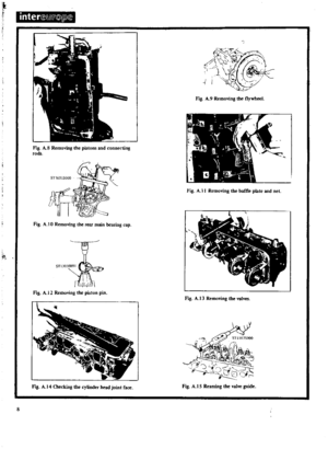 9
9 10
10 11
11 12
12 13
13 14
14 15
15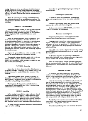 16
16 17
17 18
18 19
19 20
20 21
21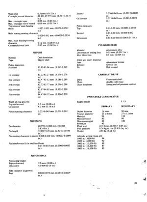 22
22 23
23 24
24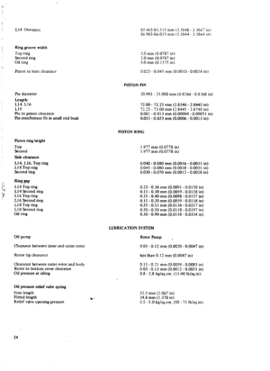 25
25 26
26 27
27 28
28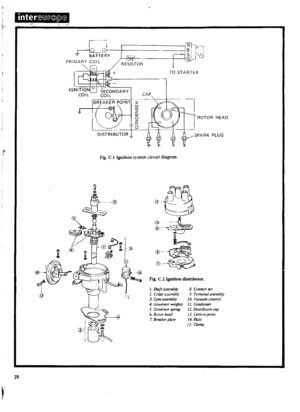 29
29 30
30 31
31 32
32 33
33 34
34 35
35 36
36 37
37 38
38 39
39 40
40 41
41 42
42 43
43 44
44 45
45 46
46 47
47 48
48 49
49 50
50 51
51 52
52 53
53 54
54 55
55 56
56 57
57 58
58 59
59 60
60 61
61 62
62 63
63 64
64 65
65 66
66 67
67 68
68 69
69 70
70 71
71 72
72 73
73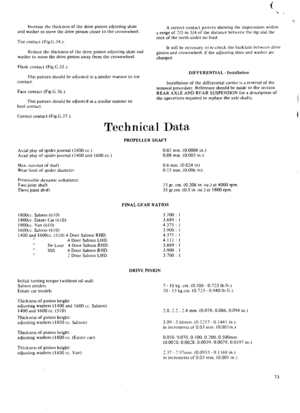 74
74 75
75 76
76 77
77 78
78 79
79 80
80 81
81 82
82 83
83 84
84 85
85 86
86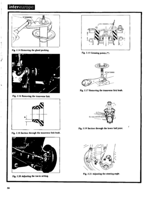 87
87 88
88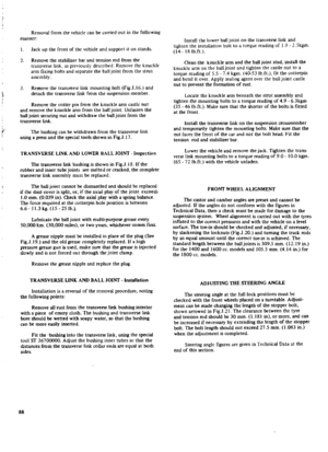 89
89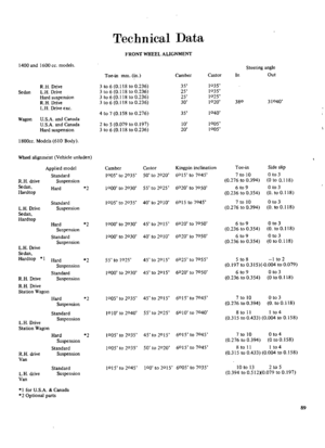 90
90 91
91 92
92 93
93 94
94 95
95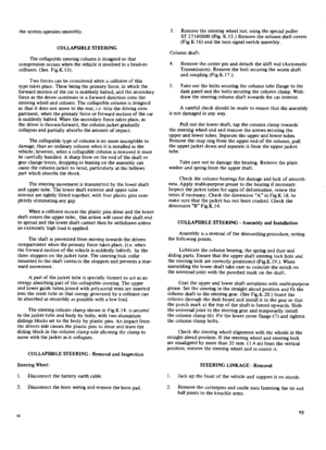 96
96 97
97 98
98 99
99 100
100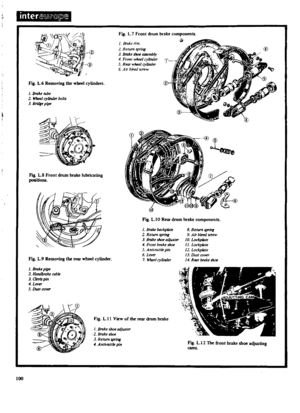 101
101 102
102 103
103 104
104 105
105 106
106 107
107 108
108 109
109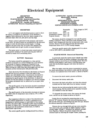 110
110 111
111 112
112 113
113 114
114 115
115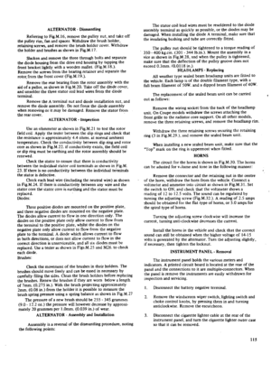 116
116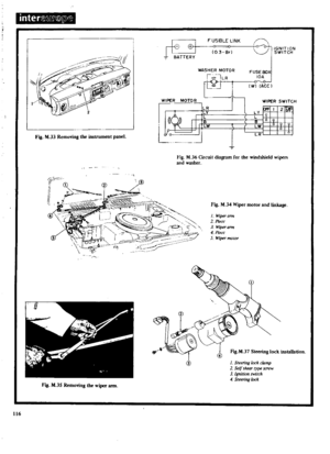 117
117 118
118 119
119 120
120 121
121 122
122 123
123 124
124 125
125 126
126 127
127 128
128 129
129 130
130 131
131 132
132 133
133 134
134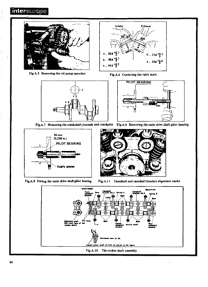 135
135 136
136 137
137 138
138 139
139 140
140 141
141 142
142 143
143 144
144 145
145 146
146 147
147 148
148 149
149 150
150 151
151 152
152 153
153 154
154 155
155 156
156 157
157 158
158 159
159 160
160 161
161 162
162 163
163 164
164 165
165 166
166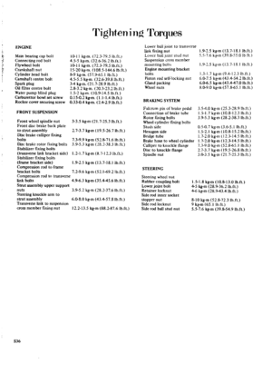 167
167 168
168 169
169 170
170


