Page 57 of 171
inter
iillu@U
Fig
F
20
Filting
the
spring
rings
Fig
F
21
Olecking
the
end
float
of
lhe
gearwheels
Fig
F
22
The
interlock
mechanism
c
Fig
F
23
Installing
the
cross
shaft
1
crossshil
t
2
l
hnut
washers
3
OperatirJ8levm
4
Lock
pim
5
Retaining
rings
Fig
F
24
Ole
king
the
gear
backlash
hk
rmJ
t
0
o
y
9
Ll
7
1
l
i
A
I
f
0
Fig
F
25
Withdrawal
lever
and
reIe
e
bearing
Fig
F
26
View
of
the
four
speed
gearbox
with
bottom
cover
removed
II
56
Page 58 of 171

FOUR
SPEED
GEARBOX
Removal
and
Installation
The
removal
and
installation
procedures
for
the
four
speed
gearbox
are
similar
to
those
previously
described
for
the
three
speed
gearbox
However
the
floor
mounted
gear
lever
must
be
removed
from
the
controllevef
bracket
in
addition
to
the
operations
already
detailed
FOUR
SPEED
GEARBOX
Dismantling
Drain
the
oil
from
the
gearbox
Remove
the
dust
coveT
and
release
the
spring
securing
the
clutch
withdrawal
lever
Remove
the
withdrawal
lever
and
release
bearing
from
the
clutch
housing
as
described
in
the
section
CLurCH
Remove
the
clevis
pin
securing
the
striking
rod
to
the
control
lever
Remove
the
speedometer
drive
pinion
assembly
and
with
draw
the
rear
extension
housing
Disengage
the
striking
rod
from
the
selector
rod
gates
Remove
the
gearbox
covers
See
Figs
F
26
and
F
27
Unscrew
the
three
detent
ball
plugs
and
remove
the
spriags
and
detent
balls
Drive
out
the
pins
securing
the
selector
forks
to
the
rods
and
withdraw
the
forks
and
rods
Lock
the
main
shaft
by
moving
the
first
second
and
third
fourth
coupling
sleeve
into
gear
at
the
same
time
and
release
the
ffiainshaft
nut
Remove
the
countershaft
and
the
gear
cluster
together
with
the
two
needle
roller
bearings
and
spacers
Remove
the
snap
ring
holding
the
revep
e
idler
gear
and
withdraw
the
reverse
idler
gears
and
shaft
Fig
F
28
Take
off
the
bolts
securing
the
mainshaft
bearing
retainer
to
the
gearbox
case
Fig
F
29
Withdraw
the
mainshaft
assembly
Fig
F
30
and
the
main
drive
shaft
The
mainshaft
can
be
dismantled
in
the
following
manner
Release
the
third
fourth
synchronizer
unit
snap
ring
and
with
draw
the
hub
complete
with
coupling
sleeve
Remove
the
third
speed
gearwheel
and
the
needle
roller
bearing
from
the
main
shaft
Take
off
the
mainshaft
nut
and
locking
plate
Remove
the
speedometer
drive
gear
with
the
retaining
ball
Withdraw
the
mainshaft
reverse
gear
and
the
hub
Press
off
the
mainshaft
bearing
complete
with
the
bearing
retainer
Remove
the
thrust
washer
and
the
first
speed
gear
together
with
the
needle
roller
bearing
taking
care
not
to
lose
the
small
baU
used
to
locate
the
thrust
washer
Slide
off
the
first
speed
gearwheel
bush
Withdraw
the
first
second
synchronizer
and
hub
Remove
the
second
speed
gearwheel
and
needle
roller
bearing
FOUR
SPEED
GEARBOX
Installation
Refer
to
the
instructions
given
for
the
three
speed
gearbox
and
to
Technical
Data
for
the
specifications
applicable
to
the
different
gearboxes
FOUR
SPEED
GEARBOX
Assembly
Assembly
of
the
gearbox
is
similar
to
the
procedures
previously
described
for
the
three
speed
gearbox
with
the
following
exceptions
When
assembling
the
main
drive
gear
bearing
on
the
shaft
insiall
the
spacer
and
select
a
new
snap
ring
to
eliminate
all
end
float
between
bearing
and
snap
ring
Snap
rings
are
available
in
five
thicknesses
from
1
52
1
77mm
0
06
0
07
in
The
assembly
procedures
for
the
Warner
type
synchronizers
are
similar
to
the
instructions
previously
described
for
the
three
speed
gearbox
Refer
to
THREE
SPEED
GEARBOX
Assembly
for
further
details
To
assemble
the
Servo
F4C63
type
synchronizers
proceed
as
follows
Place
the
gear
on
a
clean
flat
surface
and
install
the
synchronizer
ring
on
the
inner
side
of
theclutch
gear
Fit
the
thrust
block
into
place
as
shown
in
Fig
F
31
Place
the
anchor
block
and
brake
band
into
position
and
fit
the
circlip
into
the
groove
in
the
gear
to
secure
the
synchromesh
assembly
When
assembling
the
mainshaft
select
a
snap
ring
which
will
give
an
end
float
between
0
05
0
15
mm
0
002
0
006in
to
the
third
speed
gearwheel
Snap
rings
are
available
in
five
sizes
from
1
40
mm
0
0551
in
to
1
60
mm
0
0630
in
thick
ness
Tighten
the
locknut
at
the
rear
of
the
mainshaft
to
a
torque
reading
of
7
1
kgm
51
87Ib
ft
Assemble
the
reverse
idler
gear
as
shown
in
Fig
F
32
The
reverse
idler
driven
gear
3
should
be
placed
on
the
end
of
the
reverse
shaft
1
with
the
longest
spline
and
retained
with
a
suitable
snap
ring
2
Install
the
reverse
shaft
and
gear
assembly
into
the
gearbox
case
from
the
rear
with
the
thrust
washer
4
between
the
gear
and
the
case
Fit
the
thrust
washer
5
and
idler
gear
6
18
teeth
and
secure
with
a
suitable
snap
ring
2
The
end
float
of
the
gear
should
be
checked
and
adjusted
to
0
1
O
3mm
0
004
0
012
in
by
selecting
a
suitable
snap
ring
2
Five
thicknesses
of
snap
rings
are
available
from
I
lmm
0
043in
to
1
5mm
0
06in
See
Technical
Data
for
F4W63
and
F4C63
gearboxes
Adjust
the
counter
gear
end
float
to
0
05
0
15
mm
0
002
0
006in
by
selecting
a
thrust
washer
of
the
required
thickness
Thrust
washers
are
available
in
five
thicknesses
from
2
40
2
60
mm
0
094
0
102
in
When
assembling
the
selector
mechanisms
Fig
F
33
fit
the
first
second
selector
forks
I
and
the
third
fourth
selector
forks
2
onto
the
coupling
sleeves
and
insert
the
first
second
fork
rod
3
Fit
an
interlock
plunger
4
and
the
third
fourth
speed
selector
rod
5
Do
not
forget
the
interlock
pin
7
A
section
through
the
selector
and
interlock
mechanism
is
given
in
Fig
F
34
Install
an
interlock
plunger
6
and
assemble
the
reverse
selector
fork
8
and
fork
rod
9
Secure
the
selector
forks
to
the
rods
with
the
retaining
pins
10
Place
a
check
ball
and
spring
into
each
of
the
holes
and
screw
the
plug
down
to
a
torque
reading
of
1
7
2
1
Jegm
12
3
15
2
Ib
ft
after
coating
the
threads
with
sealing
com
pound
Install
the
rear
extension
housing
engaging
the
striking
rod
with
the
fork
rod
gates
and
tighten
the
housing
bolts
to
a
torque
reading
of
1
6
2
5
kgm
12
18Ib
ft
Fit
the
front
and
bottom
covers
and
tighten
the
bolts
to
a
torque
reading
of
1
1
1
8
kgm
8
13Ib
ft
57
Page 59 of 171
inter
lli
r@
ig
F
28
Re
oving
the
reverse
idler
gear
q
F
8
F
27
View
of
the
four
speed
gearbox
with
front
cover
removed
F
8
F
29
Removing
the
mainshaft
bearing
retainer
Fig
F
30
Withdrawing
the
mainshaft
assembly
CD
1ib
1
@
II
c
I
@
d
I
Q
n
j2
JJ
I
0
6
r
7
1
L
l
Hv
9
1l
ij07
u
1
1
v
1
ISland
2nd
selector
fork
5
Fork
rod
2
3rd
and
4th
selector
fork
6
Inter
ock
phmgtr
3
Fork
rod
7
Intulock
pin
4
Interlock
plunger
8
Revene
selLetor
fork
9
Fori
rod
10
Retaining
pin
Fig
F
33
Assembly
of
the
selector
forks
1
17uu
t
block
2
md
bruke
3
Synchro
rint
4
Anchor
block
5
Circlip
6
Band
b
ke
r
1
R
nt
shaft
SntJpring
3
R
idler
driving
geor
UT
4
Thrust
washer
5
1
hnat
washer
6
Idlergeor
18T
Fig
F
32
Reverse
idler
gear
F
8
F
31
Syncbromesh
assembly
3rd
4th
Rod
Fig
F
36
Removing
the
steering
wheel
Fig
F
34
Section
tIuough
the
gearbox
showing
the
inlerlock
mechanism
58
Page 60 of 171

THREE
SPEED
GEARBOX
GEARCHANGE
CONTROL
LINKAGE
Fig
F
35
As
previously
described
the
three
speed
gearbox
is
equipped
with
a
steering
column
gearchange
linkage
system
which
incorporates
a
collapsible
control
rod
when
combined
with
the
collapsible
type
of
steering
column
assembly
The
gearchange
linkage
can
be
removed
and
inspected
in
the
following
manner
Remove
the
steering
wheel
Fig
F
36
and
take
off
the
steering
column
shell
cover
Remove
the
turn
signal
and
lighting
switch
Fig
F
37
These
removal
details
can
also
be
found
in
the
section
STEERING
Remove
the
C
washer
I
in
Fig
F
38
and
the
washer
then
remove
the
upper
support
bracket
by
releasing
the
locating
bolt
and
screw
The
control
rod
insert
with
bush
and
return
spring
can
now
be
removed
Remove
the
snap
and
gear
lever
pivot
pin
and
withdraw
the
gearlever
Remove
the
cotter
pin
plain
washer
and
spring
washer
and
disconnect
the
shift
rods
from
the
gear
selector
levers
Fig
F
39
Unscrew
the
bolts
securing
the
lower
support
bracket
and
the
clamp
Remove
the
clamp
and
gear
change
lever
retainer
Remove
the
second
third
speed
selector
lever
the
lower
support
bracket
and
the
first
reverse
selector
lever
from
the
control
rod
Withdraw
the
control
rod
Disconnect
the
gear
change
rods
by
removing
the
cotter
pins
and
remove
the
cross
shaft
bracket
from
the
side
member
Withdraw
the
cross
shaft
assembly
Fig
F
40
Examine
the
components
for
signs
of
wear
and
damage
and
replace
if
necessary
Installation
is
a
reversal
of
the
removal
procedure
noting
the
following
points
Take
care
not
to
strike
or
apply
a
load
to
the
collapsible
type
of
control
rod
or
the
rod
may
be
damaged
The
rod
should
not
be
slack
in
the
axial
direction
when
installed
and
must
be
removed
if
slackness
is
detected
Coat
the
sliding
surfaces
with
grease
before
assembling
them
Acijusting
Set
the
gear
lever
to
the
neutral
position
and
temporarily
connect
the
trunnion
on
the
lower
support
bracket
to
each
rod
Fig
F41
Set
the
rod
on
the
lever
so
that
the
neutral
adjustment
grooves
on
the
upper
surface
of
the
lower
support
bracket
are
aligned
with
the
grooves
on
each
lever
When
the
adjustment
is
completed
operate
the
gear
lever
to
select
each
gear
and
make
sure
that
the
lever
can
be
moved
smoothly
and
positively
AUTOMATIC
TRANSMISSION
Gearchange
control
linkage
The
automatic
transmission
gear
change
control
linkage
can
be
removed
in
a
similar
manner
to
the
three
speed
gearbox
linkage
Carry
out
the
operations
previously
described
under
the
relevant
heading
as
far
as
the
removal
of
the
gear
lever
and
proceed
as
follows
Disconnect
the
upper
selector
rod
from
the
selector
lever
by
removing
the
cotter
pin
plain
washer
and
lock
washer
See
Fig
F
42
Remove
the
speed
range
position
plate
the
snap
ring
at
the
lower
end
of
the
control
rod
and
unscrew
and
remove
the
lower
support
bracket
Release
the
locking
screw
and
with
draw
the
selector
lever
assembly
Withdraw
the
control
rod
disconnect
the
selector
rods
and
remove
the
cross
shaft
bracket
and
cross
shaft
assembly
Clean
all
parts
and
repair
or
renew
any
part
which
is
worn
or
damaged
Installation
is
a
reversal
of
the
removal
procedure
noting
the
following
points
Coat
all
the
sliding
surfaces
with
chassis
grease
prior
to
assembling
Set
the
converter
side
lever
and
the
gear
lever
in
the
neutral
position
Install
the
upper
selector
rod
to
the
selector
lever
and
adjust
the
gear
position
plate
to
give
a
clearance
of
0
5
I
Omm
0
02
0
04
in
between
the
selector
lever
stop
pin
and
the
position
plate
The
adjustment
can
be
obtained
by
turning
the
selector
rod
adjusting
nuts
Finally
tighten
the
nuts
on
each
side
of
the
trunnion
S9
Page 61 of 171
6
T
1
0
4
k
m
7
2
10
1
h
b
Lowe
bra
ket
T
1
2
kl1
m
So
ft
lb
Change
J
P
dl
s
1
T
2
0
kg
m
S
d
Trunnion
i14
5ft
lb
k
R
b
hifirod
I
i
f
S
3
d
h
h
1m
1
L
7fOC
v
Rev
Rev
lst
lhift
le
er
Fig
F
35
Three
speed
gearchange
linkage
column
mounted
inter
IUI
j@
l
ce
Steering
gear
Fig
F
37
Removing
the
indicator
and
lighting
switch
60
k
Upper
bracket
id
m
mb
r
Control
rod
eros
shalt
e
r
i
2nd
Steerin
Reve
e
lu
Reverle
Neutral
od
3
Neutral
H
C
dl
n
3
Note
Fig
F
38
Removing
the
upper
support
bracket
lO
br
Gr
fOf
trllllett
il
ll
1
Ch
lwer
i
Fig
F
41
Neutral
setting
adjustment
T
0
35
0
5
kg
m
2
S
3
6
ft
lb
1
2
T
Tightening
torque
@
Chauis
grease
Apply
grease
to
the
points
shown
by
@
when
recnsembling
Fig
F
39
Removing
the
lower
bracket
Fig
F
42
View
of
the
selector
lever
Page 62 of 171

Gearbox
mode
Gearchange
type
Gear
ratios
I
st
gear
2nd
gear
3rd
gear
4th
gear
Reverse
Num
ber
of
teeth
on
mainshaft
Drive
gear
3rd
speed
2nd
speed
1st
speed
Reverse
Num
ber
of
teeth
on
counter
shaft
Driven
gear
3rd
speed
2nd
speed
1st
speed
Reverse
Reverse
idler
gear
Speedometer
Drive
gear
Driven
gear
Technical
Data
GENERAL
SPECIFICATIONS
R3W65
L
F4C63
F4W63L
Column
change
Floor
change
3
263
1
3382
1
1
645
I
2
013
1
1
000
1
1
312
1
1
000
1
3
355
I
3
364
1
19
22
27
25
30
31
36
34
39
3N71B
iFloor
change
Column
change
2
458
1
1458
1
1
000
1
2
098
1
30
31
29
24
21
15
15
16
14
16
18
5
19
or
17
16
CLEARANCES
AND
PLAYS
Model
R3W65L
F4W63L
Mainshaft
end
float
0
0
19mm
0
0
008
in
0
08
0
29mm
0
003
0
0
II
in
Max
mainshaft
end
float
0
20mm
0
008
in
0
30mm
0
012
in
Countershaft
end
float
0
04
0
12mm
0
002
0
005
in
0
05
0
15mm
0
002
0
006
in
Max
countcrshaft
end
float
0
20mm
0
008
in
0
20mm
0
008
in
Reverse
idler
gear
end
float
0
20
0
40mm
0
008
0
016
in
0
10
0
30
mm
0
004
0
012
In
Max
idler
gear
end
float
0
50mm
0
020
in
0
50mm
0
020
in
Gearwheel
end
float
I
st
speed
gearwheel
0
20
0
30mm
0
008
0
012
in
0
05
0
15mm
0
002
0
006
in
2nd
speed
gearwheel
0
20
0
30mm
0
008
0
012
in
0
05
0
15mm
0
002
0
006
in
3rd
speed
gearwheel
0
05
0
15mm
0
002
0
006
in
Gear
backlash
all
gears
0
05
0
20mm
0
002
0
008
in
0
05
0
20mm
0
002
0
008
in
Oearance
between
fork
and
coupling
sleeve
0
15
0
30mm
0
006
0
012
in
0
15
0
30mm
0
006
0
012
in
Mallshaft
run
out
0
15mm
0
006
in
0
25mm
OmO
in
Model
F4W63
and
F4663
R3W65
Gear
backlash
all
gears
0
05
0
14mm
0
002
0
0055
in
0
05
0
14mm
0
002
0
0055
in
Gearwheel
end
float
1
st
speed
gearwheel
0
05
0
15mm
0
002
0
0059
in
0
05
O
22mm
0
002
0
0087
in
2nd
speed
gearwheel
0
05
0
15mm
0
002
0
0059
in
0
10
0
22mm
0
0039
0
0087
in
3rd
speed
gearwheel
0
05
0
15mm
0
002
0
0059
in
Max
countershaft
end
float
0
05
0
15mm
0
002
0
0059
in
0
04
0
12mm
0
0016
0
0047
in
Reverse
idler
gear
end
float
0
05
0
15mm
0
002
0
0059
in
0
20
0
40mm
0
0079
0
0157
in
Oearance
between
baulk
ring
and
clu
tch
gear
I
2
1
6mm
0
047
0
0630
in
12
1
6mm
0
0472
0
0630
in
61
Page 63 of 171

inter
E
lill
j
lll
jIl
1
3
I
i
1r
I
An
t
1
ll
1
11
5
85
1
Sleeve
voke
arsembh
Bearillg
race
assembh
Jvumal
asst
mb
r
4
Snap
ring
5
Prope
ier
shaft
tube
assl
mblv
6
flan
oke
2
O
L
l
OIlU
39
I
JII
I
I
i
i
3
1
378
@
Fig
G
I
Section
through
the
propeller
shaft
Unit
mm
in
@
@
j
c
@
I
I
i
@
@
@
J
q
cJi
y
j
rID
@
62
Fig
G
2
Section
through
the
differential
carrier
1
Supply
rrwlti
purpose
gTet1M
to
oil
seal
lip
when
ass
mb1ing
Pinion
bearing
adjusting
lWSher
Adjust
pinion
ber
uing
X
eload
by
selecting
2
and
3
Pinio
bearing
adjusting
spacer
4
PInion
height
adiustinx
MUS1m
5
Lock
strap
6
Ring
gear
bolts
T
7
0
to
8
0
kgm
50
6
ro
578
bIt
TIghten
by
tapping
bolt
head
with
Jj41b3
hamTMr
7
Lock
pin
8
Rear
cover
9
Ring
gmr
10
Diff
mounting
member
1
J
Bolt
diff
to
diff
mounting
member
T
6
0
to
8
0kKm
43
4
0
7
8
b
ft
12
ShIlf
pinion
m1te
13
Thnl
lWlJIJer
14
Pinion
mate
15
17vust
washer
Adjust
the
backla
h
in
pinion
mate
and
ide
gear
or
the
clearance
betwun
the
differential
ctlSI
and
the
rear
fact
ofridt
gror
to
0
1
to
0
2
mm
0
0039
0
0
0079
bv
16
16
Side
ar
17
BoltsideflilngeT
1
9to
6kgm
13
710
18
8Ib
f
18
Oil
tal
Supply
chassi
grea
e
to
oil
seal
lip
Vtlhen
autmbling
19
Side
flange
20
Side
retainer
21
Bolt
side
retainer
T
0
9
to
1
2
kgm
6
5
to
8
71b
22
ring
23
Side
bearing
24
Diff
Gear
case
25
Pinion
rear
bearing
26
Dril
e
pinion
27
Pinion
front
bearing
28
Spacer
front
pilot
beaTing
29
Front
pilot
bearing
30
Oil
seal
3J
CompanionfliInge
32
Dri
pinion
nut
T
17
to
20
Jwn
122
9
0144
6Ib
fI
Page 64 of 171

Propeller
Shaft
and
DIfferentIaJ
DESCRIPTION
PROPELLER
SHAFT
DIFFERENTIAL
Removal
and
Dismantling
DIFFERENTIAL
Assembly
and
Adj
Jstment
DIFFERENTIAL
Installation
DIFFERENTIAL
Estate
car
and
van
TOOTH
CONTACT
PATTERN
Checking
DESCRIPTION
The
tubular
steel
propeller
shafts
are
shown
in
Fig
G
1
The
shaft
is
connected
to
the
drive
pinion
flange
by
a
yoke
flange
at
the
rear
and
to
the
transmission
output
shaft
by
a
splined
yoke
sleeve
at
the
front
The
Datsum
I800ce
station
wagon
and
van
has
a
three
section
shaft
in
contrast
to
the
two
piece
shaft
used
on
the
other
models
covered
by
this
manual
The
differential
carrier
houses
a
hypoid
bevel
gear
assembly
Although
this
manual
contains
dismantling
and
adjustment
procedures
for
the
differential
assembly
it
must
be
pointed
out
that
only
workshops
with
specialized
tools
and
equipment
will
be
able
to
carry
out
the
work
involved
PROPELLER
SHAFT
Removal
1
Release
the
hand
brake
jack
up
the
vehicle
at
the
fear
and
support
it
on
stands
2
Loosen
the
clamps
and
turn
the
pre
silencer
to
the
left
saloon
only
3
Remove
the
adjuster
nut
from
the
handbrake
cable
rear
adjuster
and
disconnect
the
left
hand
cable
Saloon
only
Remove
the
bolts
securing
the
centre
bearing
bracket
1800
cc
stati
n
wagon
4
Disconnect
the
fear
flange
from
the
rear
axle
flange
With
draw
the
propeller
shaft
to
the
rear
away
from
the
gear
box
mainshaft
Take
care
that
the
shaft
is
not
dropped
during
removal
or
the
balance
of
the
shaft
may
be
altered
5
Plug
the
gearbox
rear
extension
to
prevent
the
loss
of
oil
PROPELLER
SHAFT
Dismantling
and
Inspection
Oean
all
components
and
mark
them
before
dismantling
so
that
they
can
be
reassembled
in
their
original
positions
Correct
reassembly
is
most
important
otherwise
the
balance
of
the
shaft
may
be
affected
Remove
the
four
snap
rings
from
the
journal
assembly
and
withdraw
the
needle
bearing
cap
by
tapping
the
yoke
with
a
wooden
mallet
The
wear
on
the
spider
journal
diameter
must
not
exceed
0
15mm
0
006
in
the
standard
size
of
a
new
journal
is
14
7mm
0
579
in
Check
the
spider
seal
rings
and
replace
them
if
necessary
The
radial
backlash
of
the
sleeve
yoke
splines
to
gearbox
splines
should
not
exceed
0
5mm
0
002
in
Renew
the
sleeve
yoke
if
the
figures
are
in
excess
of
the
specified
value
E
Mount
the
shaft
between
the
centres
of
a
suitable
fixture
and
use
a
dial
gauge
to
check
that
the
run
out
of
the
shaft
does
not
exceed
0
6mm
0
024
in
at
the
centre
of
the
tubular
portion
The
shaft
can
only
be
straightened
with
a
hydraulic
press
it
is
advisable
however
to
renew
the
shaft
if
the
run
out
is
excessive
Check
that
the
dynamic
balance
of
the
shaft
does
not
exceed
15
grm
cm
0
208
oz
in
at
4000
r
p
m
PROPELLER
SHAFT
Assembly
and
11Istallation
r
Assembly
and
installation
is
a
reversal
of
the
removal
and
dismantling
procedures
not
the
following
points
Grease
the
needle
rollers
with
wheel
bearing
grease
before
placing
them
into
the
bearing
race
Lubricate
all
splines
with
gear
oil
Adjust
the
journal
radial
end
float
to
within
0
02mm
0
0008
in
using
a
suitable
snap
ring
Snap
rings
are
available
in
eight
thicknesses
from
2
00mm
0
079
in
to
2
14mm
0
084
in
and
are
colour
coded
as
detailed
in
Technical
Data
at
the
end
of
this
section
DIFFERENTIAL
Removal
Saloons
with
independent
rear
suspension
Remove
the
hand
brake
rear
cable
remove
the
propeller
shaft
and
drive
shafts
as
described
in
their
relevant
sections
2
Support
the
differential
with
ajack
and
remove
the
nuts
securing
the
differential
mounting
crossmemb
er
Fig
G
3
3
Remove
the
bolts
holding
the
differential
to
the
suspension
member
Withdraw
the
differential
and
jack
to
the
rear
4
Support
the
suspension
member
with
a
stand
to
prevent
the
mountings
from
becoming
twisted
or
damaged
DIFFERENTIAL
Dismantling
Before
dismantling
place
the
carrier
assembly
in
a
suitable
mounting
stand
or
special
stand
ST
06270001
and
carry
out
preliminary
checks
as
follows
Check
the
tooth
contact
pattern
of
the
crownwheel
and
pinion
by
applying
lead
oxide
to
three
or
four
teeth
of
the
crownwheel
Turn
the
crownwheel
several
times
to
obtain
an
impression
of
the
tooth
contact
pattern
Check
the
backlash
between
the
teeth
of
the
crownwheel
and
pinion
using
a
dial
gauge
The
backlash
should
be
within
0
10
0
20mm
0
004
0
008
in
63
 1
1 2
2 3
3 4
4 5
5 6
6 7
7 8
8 9
9 10
10 11
11 12
12 13
13 14
14 15
15 16
16 17
17 18
18 19
19 20
20 21
21 22
22 23
23 24
24 25
25 26
26 27
27 28
28 29
29 30
30 31
31 32
32 33
33 34
34 35
35 36
36 37
37 38
38 39
39 40
40 41
41 42
42 43
43 44
44 45
45 46
46 47
47 48
48 49
49 50
50 51
51 52
52 53
53 54
54 55
55 56
56 57
57 58
58 59
59 60
60 61
61 62
62 63
63 64
64 65
65 66
66 67
67 68
68 69
69 70
70 71
71 72
72 73
73 74
74 75
75 76
76 77
77 78
78 79
79 80
80 81
81 82
82 83
83 84
84 85
85 86
86 87
87 88
88 89
89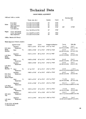 90
90 91
91 92
92 93
93 94
94 95
95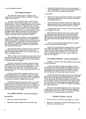 96
96 97
97 98
98 99
99 100
100 101
101 102
102 103
103 104
104 105
105 106
106 107
107 108
108 109
109 110
110 111
111 112
112 113
113 114
114 115
115 116
116 117
117 118
118 119
119 120
120 121
121 122
122 123
123 124
124 125
125 126
126 127
127 128
128 129
129 130
130 131
131 132
132 133
133 134
134 135
135 136
136 137
137 138
138 139
139 140
140 141
141 142
142 143
143 144
144 145
145 146
146 147
147 148
148 149
149 150
150 151
151 152
152 153
153 154
154 155
155 156
156 157
157 158
158 159
159 160
160 161
161 162
162 163
163 164
164 165
165 166
166 167
167 168
168 169
169 170
170

