Page 49 of 171
inter
1D7
J
3
T
T
aj
W
n
J
I
1
T
f
T
7
e
Fig
E
II
Adjustillll
the
height
of
the
release
levers
Fig
E
12
Actuating
the
clutch
to
settle
the
mechanism
Tightening
torque
3
5
to
4
0
kltm
125
to
29
h
lb
Rs
@
A
l
I
l
1
3
fP
I
01
I
8J
I
Jt
I
Lock
A
2
Lock
ul
Bn
Adjwt
by
adjust
of
master
cyl
@
Lubricatic
l
Clutch
dal
full
trek
140
4
mm
5
51
0
16
Clutch
pedal
free
stroke
25
mm
0
98
Pedal
height
175
mm
6
89
nl
Pc
dalfullstrokc
b
135mm
5
JI
n
@
Multi
purpo
greasc
510
series
610
series
Fig
E
l3
Adjusting
the
clutch
pedal
I
48
Page 50 of 171
inter
lliJ
j
flDlJ
l
Jl
iO
n
cxB
L
of
lii
t
hl
9
q
6
15
1
r
8t
r
L
L
I
i
1
2
9
@
7
5I1
9
QlIf12
12J
J
7
ll
I
I
o
Q
1
Cylinder
2
Return
spring
3
Piston
4
Secondary
cup
5
Piston
cup
6
Supply
valve
seat
7
Supply
valve
stem
8
Supply
lIOlve
spring
9
Spring
seat
10
Va
ve
stem
stop
11
Stopper
gasket
12
Gasket
ring
13
Push
rod
14
Push
rod
ht
lld
15
Wdd
nut
16
Lock
nut
17
Piston
stopper
18
Stopper
ring
19
Boots
20
Oil
reservoir
21
Rese1l
Oir
band
22
Reservoir
cop
23
Cap
24
Pipe
seat
J
J
5
9
a
ID
1
Cylinder
2
Return
spring
C1
3
Piston
4
Spring
seat
5
Push
rod
6
Nut
7
Stopper
ring
8
Stopper
9
Dust
cover
10
on
reservoir
1
J
Reservoir
balld
12
Reservoir
cap
Fig
E
14
Section
through
the
clutch
master
cylinder
Adjusting
nut
Fig
E
l
S
Adjusting
the
clutch
withdrawal
lever
49
Page 51 of 171

other
end
of
the
tube
into
a
clean
container
partly
filled
with
brake
fluid
Top
up
the
master
cylinder
reservoir
with
recommended
fluid
and
open
the
bleed
screw
approximately
three
quarters
of
a
turn
Depress
the
clutch
pedal
slowly
and
hold
it
completely
down
re
tighten
the
bleed
screw
and
allow
the
pedal
to
return
slowly
Repeat
the
operation
until
the
fluid
emerging
from
the
tube
is
free
from
air
bubbles
It
should
be
noted
that
assistance
will
be
required
when
carrying
out
bleeding
operations
as
not
only
must
the
fluid
entering
the
glass
container
be
watched
but
also
the
clutch
pedal
has
to
be
operated
and
the
reservoir
topped
up
frequently
throughout
the
procedure
When
the
fluid
is
completely
free
from
air
bubbles
the
bleed
screw
should
be
retightened
on
a
down
stroke
of
the
pedal
Finally
remove
the
bleed
tube
and
replace
the
dust
cap
TechnIcal
Data
Outch
type
Pressure
spring
Free
length
Fitted
length
and
load
Side
distortion
Permissible
deterioration
of
spring
force
Outch
release
levers
Oearance
between
release
bearing
and
diaphragm
spring
release
levers
Height
between
diaphragm
spring
and
flywheel
Height
between
release
levers
and
flywheel
Outch
driven
plate
Outer
diameter
Inner
diameter
Thickness
of
facingS
Total
friction
area
TIrickness
of
clutch
plate
Free
Compressed
No
of
torsion
springs
Permissible
minimum
depth
of
rivet
heads
from
facing
surface
Permissible
run
out
of
clutch
facing
P
rmissible
free
play
of
splines
Outch
pedal
1400
and
1600cc
models
Pedal
height
in
the
rest
position
P
da1
free
stroke
P
da1
effort
Master
cylinder
Diameter
Maximum
clearance
between
piston
and
cylinder
Pressure
plate
Permissible
refacing
limit
Outch
pedal
180Occ
models
P
da1
height
Play
at
clevis
pin
Full
stroke
P
da1
effort
50
Diaphragm
spring
or
coil
spring
52
3mm
2
059
in
29
2mm
44
2kg
1
149
in
197
t
4
4
lb
5mm
per
IOOmm
0
2in
per
3
94
in
15
1
2
I
4mm
0
047
0
055
in
44
t
Imm
1
732
t
0
039
in
50
5
t
0
05mm
1
988
t
0
0197
in
200mm
7
87
in
130mm
5
12in
3
5mm
0
140in
362
sq
cm
56
11
sq
in
8
6
9
0mm
0
3386
o
3543in
7
65
7
95mm
0
3012
o
3130in
6
O
3mm
0
0118
in
0
5mm
0
0197
in
0
4mm
0
0157
in
182mm
7
17in
R
H
D
207mm
8
15in
L
H
D
25mm
0
984in
15kg
33
lb
15
87mm
0
625in
O
13mm
0
005lin
Imm
0
0394in
175mm
6
89in
1
5mm
0
04
0
20in
135mm
5
3lin
10
5kg
23Ib
Page 52 of 171

Gearbox
GEARBOX
Removal
GEARBOX
Dismantling
GEARBOX
Inspection
and
Overhaul
GEARBOX
Assembling
THREE
SPEED
GEARBOX
GEARCHANGE
CONTROL
Removal
and
Adjusting
AUTOMATIC
TRANSMISSION
Gearchange
control
linkage
DESCRIPTION
Three
types
of
transmission
are
available
for
the
Datsun
models
covered
by
this
manual
Either
a
three
speed
gearbox
a
four
speed
gearbox
or
three
speed
automatic
transmission
can
be
fitted
The
three
and
four
speed
gearboxes
are
equipped
with
nchromesh
on
all
forward
gears
with
the
three
speed
gearbox
operated
by
a
steering
column
gearchange
system
and
the
four
speed
gearbox
by
a
floor
mounted
gear
lever
Two
types
of
synchromesh
are
used
in
the
four
speed
gearboxes
Either
Borg
Warner
or
Servo
types
may
be
fitted
The
gearboxes
differ
only
in
the
synchromesh
devices
whereby
the
baulk
rings
synchronize
the
coupling
sleeve
with
the
main
shaft
gear
on
the
Warner
gearbox
This
action
is
accomplished
by
a
synchrcrring
on
the
servo
gearbox
THREE
SPEED
GEARBOX
Removal
I
Jack
up
the
vehicle
and
support
it
on
stands
2
Disconnect
the
hand
brake
cable
at
the
equalizer
bracket
Slacken
the
two
exhaust
pipe
centre
clamps
and
turn
the
centre
section
of
the
exhaust
assembly
to
the
left
as
shown
in
Fig
F
2
3
Disconnect
the
propeller
shaft
from
the
rear
axle
drive
flange
by
removing
the
four
securing
bolts
Seal
off
the
gearbox
extension
housing
to
prevent
the
loss
of
oil
and
withdraw
the
shaft
to
the
rear
4
Disconnect
the
speedometer
drive
cable
from
the
adaptor
in
the
gearbox
extension
housing
Fig
F3
S
Disconnect
the
lower
shift
rods
from
the
shift
levers
Fig
F
4
and
remove
the
cross
shaft
assembly
from
the
gearbox
casing
Remove
the
clutch
slave
cylinder
from
the
clutch
housing
Fig
F
5
6
Support
the
engine
with
ajack
positioned
underneath
the
oil
sump
making
sure
that
the
jack
does
not
foul
the
drain
plug
A
block
of
wood
should
be
placed
between
the
sump
and
jack
to
avoid
damaging
the
sump
7
Remove
the
bolts
securing
the
rear
engine
mounting
to
the
crossmember
Position
ajack
under
the
gearbox
and
remove
the
bolts
attaching
the
crossmember
to
the
body
Lower
the
jack
under
the
engine
so
that
the
engine
is
tilted
to
the
rear
Remove
the
starter
motor
and
the
bolts
securing
the
clutch
housing
to
the
engine
Lower
the
jack
slowly
and
withdraw
the
gearbox
towards
the
rear
of
the
vehicle
THREE
SPEED
GEARBOX
Dismantling
Drain
the
gearbox
oil
Remove
the
dust
cover
release
the
retainer
spring
and
remove
the
withdrawal
lever
complete
with
release
bearing
from
the
clutch
housing
See
section
CLUTCH
Remove
the
gearbox
bottom
cover
the
speedometer
drive
pinion
assembly
and
the
rear
extension
housing
Take
out
the
cross
shaft
retaining
rings
and
unscrew
the
nuts
securing
the
operating
lever
lock
pins
Use
a
hammer
and
punch
to
drive
out
the
pins
and
withdraw
both
cross
shafts
Fig
F
6
Remove
the
fr
mt
cover
and
withdraw
the
counter
shaft
Lift
out
the
countersbaft
gear
cluster
together
with
the
needle
roller
bearings
and
spacers
Fig
F
7
Remove
the
reverse
idler
gear
shaft
lock
bolt
and
remove
the
shaft
and
the
idler
gear
Fig
F
B
Drive
out
the
pins
securing
the
selector
forks
to
the
selector
rods
Unscrew
the
interlock
plug
and
remove
the
detent
ball
and
spring
Fig
F
9
Remove
the
first
reverse
speed
and
second
third
speed
selector
rods
and
lift
out
the
selector
forks
Withdraw
the
main
shaft
assembly
and
the
drive
shaft
assembly
from
the
gearbox
See
Fig
F
1O
and
F
11
To
dismantle
the
mainshaft
release
the
circlip
from
the
front
of
the
mainshaft
as
shown
in
Fig
F
12
and
remove
the
second
and
third
speed
synchronizer
hub
and
second
speed
gearwheel
Fig
F
13
Remove
the
circlip
securing
the
speedo
meter
drive
gear
and
withdraw
the
gear
together
with
the
ball
and
spacer
Fig
F
14
Remove
the
mainshaft
bearing
using
a
press
Hold
the
rnainshaft
reverse
gear
and
tap
the
shaft
on
a
piece
of
wood
to
release
the
reverse
gear
assembly
together
with
the
first
speed
gearwheel
GEARBOX
Inspection
and
Overhaul
Oean
all
parts
thoroughly
and
examine
the
gearbox
case
and
extension
housing
for
cracks
If
the
joint
faces
are
burred
or
pitted
it
may
be
necessary
to
replace
the
units
if
repair
cannot
be
carried
out
satisfactorily
Remove
any
adhesive
which
remains
on
the
faces
The
rear
extension
housing
bush
should
be
renewed
if
worn
unevenly
Clean
the
bearings
and
dry
with
compressed
air
taking
care
that
the
bearings
do
not
spin
Turn
the
ball
bearings
to
make
sure
that
they
run
smoothly
and
without
play
Replace
the
needle
bearings
if
worn
or
damaged
in
any
way
It
is
advisable
to
renew
the
needle
roller
bearings
after
they
have
been
installed
for
a
considerable
period
as
it
is
difficult
51
Page 53 of 171
VP
F
rr
l
I
lip
J
I
I
ii
iI
a
l
Fig
F
1
View
through
the
four
speed
gearbox
It
j
j
4
C
J
f
e
V
tJ
J
I
P
Fig
F
2
The
propeUer
shaft
Fig
F
3
Disconnecting
the
speedometer
cable
Fig
F
4
Disconnecting
the
remote
control
linkage
Fig
F
5
Removing
the
clutch
slave
cylinder
52
Page 54 of 171
jiii
c
c
inteN
I
j
D
p
Fig
F
7
Removing
the
countershaft
gear
Fig
F
6
Removing
the
ero
shaft
tT
l
Fig
F
S
Removing
the
reverse
idler
gear
JO
Fig
F
9
Removing
the
interlock
plug
F
8
F
I
0
Withdrawing
the
mainshaft
gear
assembly
Fig
F
lI
Removing
the
main
drive
shaft
Fig
F
12
Removing
the
2nd
and
3rd
speed
syndlroniur
hub
circlup
f
Ii
ii
jjf
vr
O
Fig
F
13
Removins
the
2nd
and
3rd
speed
hub
and
2nd
speed
gearwheel
S3
Page 55 of 171
i
nte
r
IJ
j
J
D
W
J
Fig
F
14
Rc
the
speedometer
drive
gear
and
spacer
Fill
F
15
Checking
the
IIlJIDlShofllor
ron
ol
Fig
F
I
7
Installing
the
insert
snap
ring
Fill
F
16
Checking
the
clearance
between
baulk
ring
and
gear
Fig
F
18
InsWlins
the
shifting
inserlll
54
Fig
F
19
Fitting
the
synchronizer
hub
to
the
coupling
sleeve
Page 56 of 171

to
ascertain
the
amount
of
wear
that
has
taken
place
Check
the
teeth
of
the
gearwheels
and
the
machined
surfaces
for
signs
of
wear
scoring
pitting
and
burrs
Ensure
that
the
synchronizer
hubs
slide
freely
on
the
splines
of
the
main
shaft
with
minimum
clearance
Check
the
mainshaft
for
run
out
using
V
blocks
and
a
dial
gauge
as
shown
in
Fig
F
15
Renew
the
mainshaft
if
the
run
out
exceeds
0
15mm
0
0059
in
Check
the
synchronizer
rings
for
wear
and
renew
them
if
necessary
Place
the
rings
in
position
on
their
respective
gear
wheel
cones
and
check
the
gap
between
the
end
of
the
ring
and
the
front
face
of
the
teeth
Fig
F
16
The
correct
gap
should
be
within
1
2
1
6mm
0
047
0
063
in
Renew
the
synchronizer
ring
if
the
gap
is
less
than
0
8mm
0
0315
in
Place
the
selector
rods
on
a
flat
surface
and
check
them
for
traightness
Renew
any
rod
which
is
bent
Renew
the
locking
pins
and
interlock
balls
if
they
are
worn
or
damaged
The
standard
clearance
between
the
selector
forks
and
operating
sleeve
groove
is
0
15
0
30mm
0
006
0
012
in
Make
sure
that
the
oil
seals
are
satisfactory
and
discard
the
O
rings
THREE
SPEED
GEARBOX
Assembly
Press
the
main
drive
gear
bearing
onto
the
main
drive
shaft
and
fit
the
spacer
Select
a
snap
ring
of
suitable
thickness
so
that
all
play
is
eliminated
between
the
bearing
and
snap
ring
Seven
sizes
of
snap
rings
are
available
and
vary
in
thickness
from
1
52mm
0
0598
in
to
1
89mm
0
0747in
The
synchromesh
unit
consists
of
a
coupling
sleeve
baulk
ring
spring
synchronizer
hub
and
insert
When
assembling
the
unit
make
sure
that
the
correct
insert
pressure
springs
are
fitted
to
the
relevant
speed
unit
The
first
reverse
gear
synchronizer
should
be
fitted
with
the
three
coil
spring
type
and
the
second
third
gear
synchronizer
with
the
two
expanding
springs
To
assemble
the
fiI3t
speed
synchronizer
insert
the
sliding
insert
snap
ring
onto
the
synchronizer
hub
as
shown
in
Fig
F
17
Fit
the
sliding
inserts
Fig
F
18
and
the
synchronizer
springs
on
the
synchronizer
hub
and
assemble
the
synchronizer
hub
complete
with
inserts
into
the
coupling
sleeve
Fig
F
19
Assemble
the
second
third
gear
synchronizer
hub
and
coupling
sleeve
making
sure
that
the
sleeve
slides
freely
on
the
hub
splines
Fit
the
three
shifting
inserts
and
install
a
spring
ring
on
each
side
of
the
hub
Fig
F
20
To
assemble
the
mainshaft
start
from
the
front
end
of
the
shaft
and
slide
the
second
speed
gearwheel
on
to
the
shaft
with
the
tapered
cone
facing
forwards
Install
the
baulk
ring
on
the
gearwheel
and
place
the
second
third
speed
synchronizer
assembly
on
the
front
end
of
the
shaft
and
retain
it
with
a
snap
ring
which
will
give
an
end
play
of
0
05
0
25
mm
0
002
0
009
in
Snap
rings
are
available
in
five
sizes
from
1
60
1
80
mm
0
063
0
071
in
Fit
the
first
speed
gear
and
baulk
ring
on
the
rear
of
the
shaft
so
that
the
tapered
cone
faces
to
the
rear
Assemble
the
first
speed
synchronizer
and
reverse
gear
on
the
shaft
Fit
the
spacer
and
press
the
mainshaft
bearing
complete
with
retainer
onto
the
shaft
Install
the
spacer
ball
and
speedometer
drive
pinion
Select
a
snap
ring
which
will
give
an
end
float
of
0
05
0
22mm
0
002
0
009
in
on
the
mainshaft
first
gear
Snap
rings
are
available
in
eight
thicknesses
from
1
30mrn
0
0512
in
to
1
70mm
0
0669
in
Secure
the
drive
gear
with
the
selected
snap
ring
and
check
the
end
float
of
the
gearwheels
as
shown
in
Fig
F
21
The
correct
end
float
should
be
as
follows
I
st
speed
gearwheel
0
2
o
3mm
0
008
0
012
in
0
2
0
3mm
0
008
0
012
in
2nd
speed
gearwheel
Fit
the
main
drive
gear
and
mainshaft
assembly
into
the
gearbox
casing
Fit
the
selector
rods
and
forks
as
follows
Turn
the
gearbox
casing
so
that
the
detent
ball
hole
is
uppermost
and
insert
the
spring
and
ball
in
the
bottom
of
the
hole
Hold
the
ball
witb
a
dummy
shaft
and
install
tbe
first
reverse
selector
fork
and
rod
pushing
the
dummy
shaft
out
of
position
Insert
the
interlocking
plunger
and
fit
the
second
third
speed
selector
fork
and
rod
Insert
the
steel
ball
and
spring
and
refit
the
interlocking
plug
after
coating
the
threads
of
the
plug
with
sealing
compound
See
Fig
F
22
Secure
the
selector
forks
to
the
rods
by
inserting
the
retaining
pins
Fit
the
reverse
idler
gear
and
shaft
and
secure
the
shaft
with
the
lock
bolt
and
plate
Insert
the
counter
gear
cluster
and
shaft
using
a
suitable
thrust
washer
to
obtain
an
end
float
of
0
04
0
12
mm
0
0016
0
0047
in
Thrust
washers
are
available
in
five
sizes
from
3
85
4
05
mm
0
1516
0
1594
in
thickness
in
increments
of
0
05
mm
0
002
in
Fit
the
cross
shafts
1
in
Fig
F
23
the
thrust
washers
2
and
the
operating
levers
3
Secure
the
cross
shafts
with
the
retaining
rings
5
and
lock
the
operating
levers
to
the
shafts
with
the
pins
4
Locate
the
rear
extension
housing
on
the
gearbox
case
and
tighten
the
bolts
to
a
torque
reading
of
2
8
4
4
kgm
20
32
Ib
ft
Insert
the
speedometer
drive
pinion
and
retain
it
with
the
set
bolt
and
lock
plate
Check
the
backlash
of
all
the
gears
using
a
dial
gauge
as
shown
in
Fig
F
24
The
backlash
should
be
between
0
05
0
20
mm
0
002
0
008
in
Fit
the
gearbox
front
cover
and
tighten
the
fixing
bolts
to
a
torque
reading
of
1
I
1
7
kgm
8
0
12
3
lb
ft
taking
care
not
to
damage
the
oil
seal
Fit
the
clutch
release
bearing
and
with
drawallever
Fig
F
25
Replace
the
bottom
cover
and
tighten
the
bolts
to
a
torque
reading
of
1
I
1
7
kgm
8
0
12
31b
ft
THREE
SPEED
GEARBOX
Installation
Installation
of
the
gearbox
is
a
reversal
of
the
removal
procedure
noting
the
following
points
Fit
the
gearbox
with
I
7
litre
0
45
US
gall
0
37
Imp
gall
of
MP
90
gear
oil
Adjust
the
clutch
slave
cylinder
push
rod
as
described
in
the
section
CLUTCH
to
provide
a
free
play
of
2
2
mm
0
087in
at
the
withdrawal
lever
55
 1
1 2
2 3
3 4
4 5
5 6
6 7
7 8
8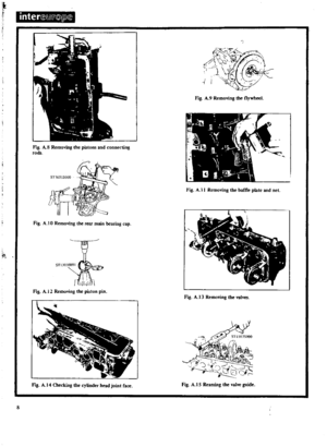 9
9 10
10 11
11 12
12 13
13 14
14 15
15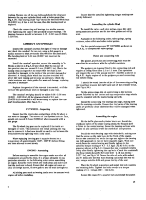 16
16 17
17 18
18 19
19 20
20 21
21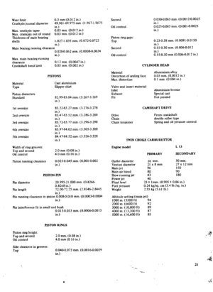 22
22 23
23 24
24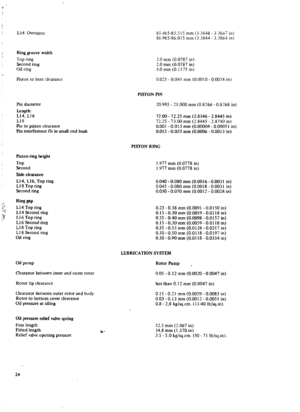 25
25 26
26 27
27 28
28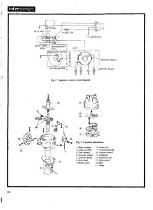 29
29 30
30 31
31 32
32 33
33 34
34 35
35 36
36 37
37 38
38 39
39 40
40 41
41 42
42 43
43 44
44 45
45 46
46 47
47 48
48 49
49 50
50 51
51 52
52 53
53 54
54 55
55 56
56 57
57 58
58 59
59 60
60 61
61 62
62 63
63 64
64 65
65 66
66 67
67 68
68 69
69 70
70 71
71 72
72 73
73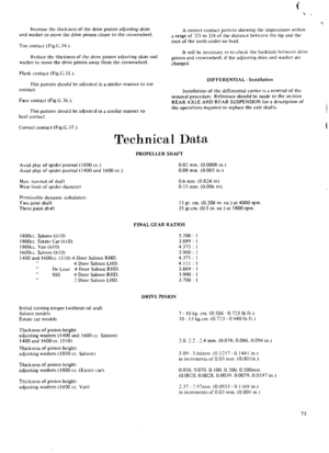 74
74 75
75 76
76 77
77 78
78 79
79 80
80 81
81 82
82 83
83 84
84 85
85 86
86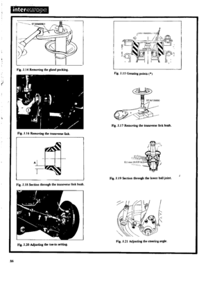 87
87 88
88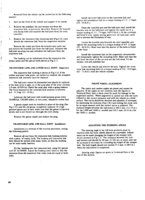 89
89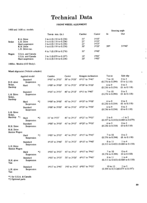 90
90 91
91 92
92 93
93 94
94 95
95 96
96 97
97 98
98 99
99 100
100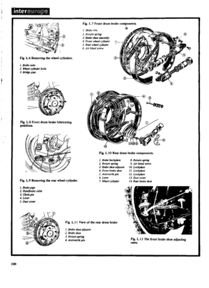 101
101 102
102 103
103 104
104 105
105 106
106 107
107 108
108 109
109 110
110 111
111 112
112 113
113 114
114 115
115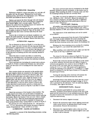 116
116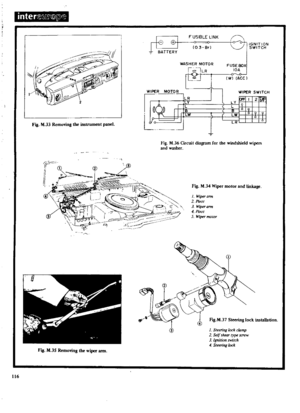 117
117 118
118 119
119 120
120 121
121 122
122 123
123 124
124 125
125 126
126 127
127 128
128 129
129 130
130 131
131 132
132 133
133 134
134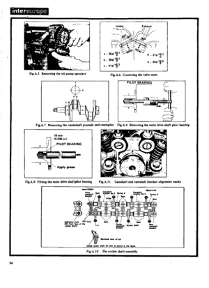 135
135 136
136 137
137 138
138 139
139 140
140 141
141 142
142 143
143 144
144 145
145 146
146 147
147 148
148 149
149 150
150 151
151 152
152 153
153 154
154 155
155 156
156 157
157 158
158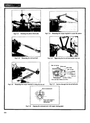 159
159 160
160 161
161 162
162 163
163 164
164 165
165 166
166 167
167 168
168 169
169 170
170


