1900 MITSUBISHI DIAMANTE oil pressure
[x] Cancel search: oil pressurePage 96 of 408
ENGINEANDENGINEOVERHAUL 3-35
Operating the engine without the proper
amount and type of engine oil will result in
severe engine damage.
33. Connect the negative battery cable and start
the engine.
34. Verify correct oil pressure
35. Inspect for leaks.
3.OL Engines
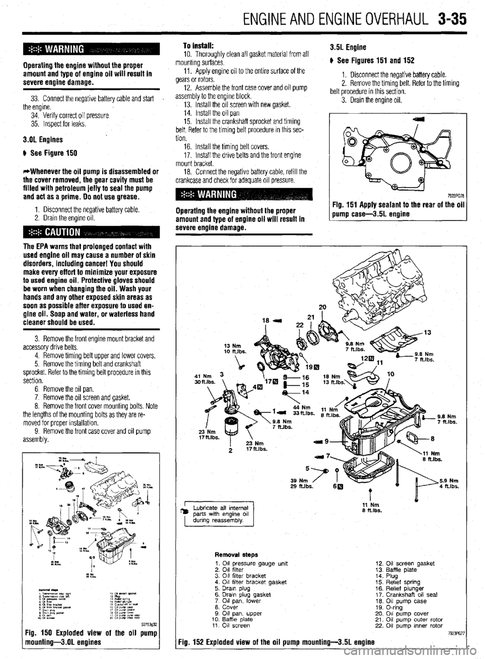
b See Figure 150
*Whenever the oil pump is disassembled or
the cover removed, the gear cavity must be
filled with petroleum jelly to seal the pump
and act as a prime. 00 not use grease.
1. Disconnect the negative battery cable.
2. Drain the engine oil.
The EPA warns that prolonged contact with
used engine oil may cause a number of skin
disorders, including cancer! You should
make every effort to minimize your exposure
to used engine oil. Protective gloves should
be worn when changing the oil. Wash your
hands and any other exposed skin areas as
soon as possible after exposure to used en-
gine oil. Soap and water, or waterless hand
cleaner should be used.
3. Remove the front engine mount bracket and
accessory drive belts.
4. Remove timing belt upper and lower covers.
5. Remove the timing belt and crankshaft
sprocket. Refer to the timing belt procedure in this
section.
6 Remove the oil pan.
7. Remove the oil screen and gasket.
8. Remove the front cover mounting bolts. Note
the lengths of the mounting bolts as they are re-
moved for proper installation.
9. Remove the front
assembly. and oil pump
9315393i 7g. 150 Exploded view of the oil pump
nounting-3.01 engines
To install:
10. Thoroughly clean all gasket material from all
mounting surfaces.
11. Apply engine oil to the entire surface of the
gears or rotors.
12. Assemble the front case cover and oil pump
assembly to the engine block.
13. Install the oil screen with new gasket.
14. Install the oil pan
15. Install the crankshaft sprocket and timing
belt. Refer to the timing belt procedure in this sec-
tion 3.5L Engine
p See Figures 151 and 152
1. Disconnect the negative battery cable.
2. Remove the timing belt. Refer to the timing
belt procedure in this section.
3. Drain the engine oil.
16. Install the timing belt covers.
17. Install the drive belts and the front engine
mount bracket.
18. Connect the negative battery cable, refill the
crankcase and check for adequate oil pressure.
Operating the engine without the proper
amount and type of engine oil will result in
severe engine damage. Fig. 151 Apply sealant to the rear of the oil
pump case-3.5L ermine
I 11 Nm
8 ft.lbs.
Removal steps
7g. 152 Exploded view of the oil pump mounting-3.51 engine
1. 011 pressure gauge unit
2. 011 filter
3. 011 filter bracket
4. 011 filter bracket gasket
5. Drain plug
6. Drawn plug gasket
7 011 lower pan,
8. Cover
9 011 pan, upper
10. Baffle date 11. 011 screen
12.
13.
14.
15.
16.
17.
10.
19.
20.
21.
22. Oil screen gasket
Baffle plate
Plug
Reltef spring
Relief plunger
Crankshaft oil seal
Oil pump case
0-ring
011 pump cover
011 pump outer rotor
011 pump inner rotor
Page 98 of 408
ENGINEANDENGINEOVERHAUL 3-37
1. Ben
2. Power4teerlna Dump 7. washer
8. Crankshaft pullet
9. Damper pulls
10. upper ccwer
11. Lowercowr
12. llmingbeil
13. crsnkshat? E#ocket 14. Flsnge
i 5. Tensbner spacer
16. Tef~kner WkW
1; Tgibnrr
19: camehan sprocket
91251ga
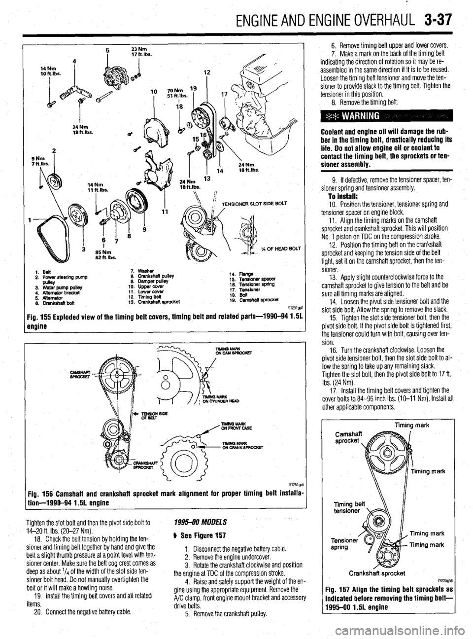
Fig. 155 Exploded view of the timing belt covers, timing belt and related parts-1990-94 1.51
engine
Fig. 156 Camshaft and crankshaft sprocket mark alignment for proper timing belt installa-
tion-1990-94 1.51 engine
Tighten the slot bolt and then the pivot side bolt to
14-20 ft. Ibs. (20-27 Nm).
18. Check the belt tension by holding the ten-
sioner and timing belt together by hand and give the
belt a slight thumb pressure at a point level with ten-
sioner center. Make sure the belt cog crest comes as
deep as about l/4 of the width of the slot side ten-
sioner bolt head. Do not manually overtighten the
belt or it will make a howling noise.
19. Install the timing belt covers and all related
items. 1995-00 MOOFLS
) See Figure 157
1. Disconnect the negative battery cable.
2. Remove the engine undercover.
3. Rotate the crankshaft clockwlse and position
the engine at TDC of the compression stroke.
4. Raise and safely support the weight of the en-
gine using the appropriate equipment. Remove the
A/C clamp, front engine mount bracket and accessory
drive belts.
20. Connect the negative battery cable.
5. Remove the crankshaft pulley. 6. Remove timing belt upper and lower covers.
7. Make a mark on the back of the timing belt
indicating the direction of rotation so it may be re-
assembled in the same direction if it is to be reused.
Loosen the timing belt tensioner and move the ten-
sioner to provide slack to the timing belt. Tighten the
tensioner in this position.
8. Remove the timing belt.
Coolant and engine oil will damage the rub-
ber in the timing belt, drastically reducing its
life. Do not allow engine oil or coolant to
contact the timing belt, the sprockets or ten-
sioner assembly.
9. If defective, remove the tensioner spacer, ten-
sioner spring and tensioner assembly.
To install: 10. Position the tensioner, tensioner spring and
tensioner spacer on engine block.
11. Align the timing marks on the camshaft
sprocket and crankshaft sprocket. This will position
No. 1 piston on TDC on the compression stroke.
12. Position the timing belt on the crankshaft
sprocket and keeping the tension side of the belt
tight, set it on the camshaft sprocket, then the ten-
sioner.
13. Apply slight counterclockwise force to the
camshaft sprocket to give tension to the belt and be
sure all timing marks are aligned.
14. Loosen the pivot side tensioner bolt and the
slot side bolt. Allow the spring to remove the slack.
15. Tighten the slot side tensioner bolt, then the
pivot side bolt. If the pivot side bolt is tightened first,
the tensioner could turn with bolt, causing over ten-
sion.
16. Turn the crankshaft clockwise. Loosen the
pivot side tensioner bolt, then the slot side bolt to al-
low the spring to take up any remaining slack.
Tighten the slot bolt, then the pivot side bolt to 17 ft.
Ibs. (24 Nm).
17. Install the timing belt covers and tighten the
cover bolts to 84-96 inch Ibs. (E-11 Nm). Install all
other applicable components.
liming mark
ming mark
Timing mark
Timing mark
Crankshaft sprocket
79235g5t Fig. 157 Align the timing belt sprockets as
indicated before removing the timing belt-
1995-00 1.51 engine
Page 100 of 408
.
ENGlNEANDENGlliEOVERHAUL 3-39
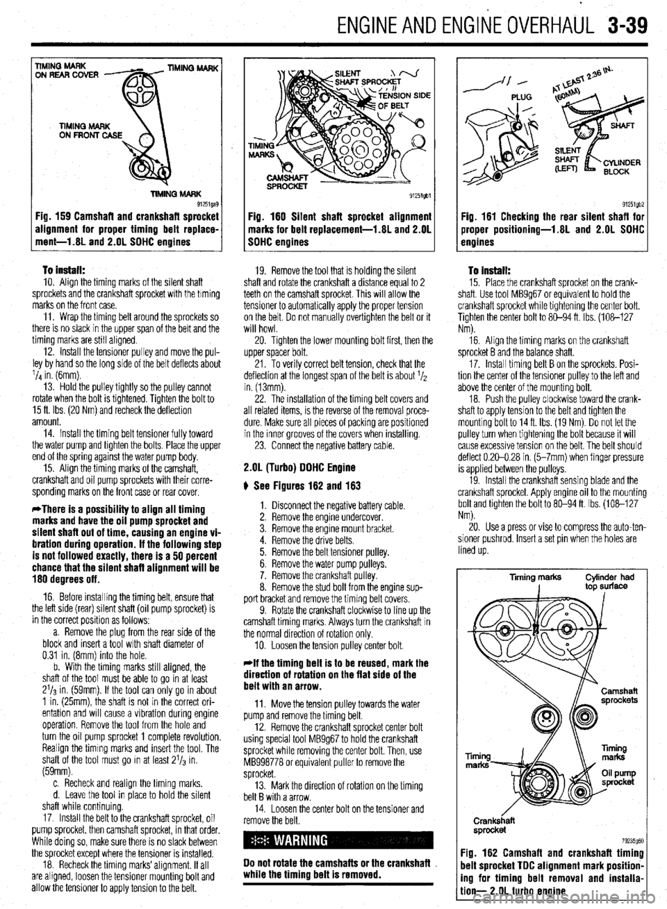
To install: IO. Align the timing marks of the silent shaft
sprockets and the crankshaft sprocket with the timing
marks on the front case.
11. Wrap the timing belt around the sprockets so
there is no slack in the upper span of the belt and the
timing marks are still aligned.
12. Install the tensioner pulley and move the pul-
ley by hand so the long side of the belt deflects about
l/d in. (6mm).
13. Hold the pulley tightly so the pulley cannot
rotate when the bolt is tightened. Tighten the bolt to
15 ft. Ibs. (20 Nm) and recheck the deflection
amount.
14. Install the timing belt tensioner fully toward
the water pump and tighten the bolts. Place the upper
end of the spring against the water pump body.
15. Align the timing marks of the camshaft,
crankshaft and oil pump sprockets with their corre-
sponding marks on the front case or rear cover.
*There is a possibility to align all timing
marks and have the oil pump sprocket and
silent shaft out of time, causing an engine vi-
bration during operation. If the following step
is not followed exactly, there is a 50 percent
chance that the silent shaft alignment will be
180 degrees off.
16. Before installing the timing belt, ensure that
the left side (rear) silent shaft (oil pump sprocket) is
in the correct position as follows:
a. Remove the plug from the rear side of the
block and insert a tool with shaft diameter of
0.31 in. (8mm) into the hole.
b. With the timing marks still aligned, the
shaft of the tool must be able to go in at least
2’13 in. (59mm). If the tool can only go in about
1 in. (25mm), the shaft is not in the correct ori-
entation and will cause a vibration during engine
operation. Remove the tool from the hole and
turn the oil pump sprocket 1 complete revolution.
Realign the timing marks and insert the tool. The
shaft of the tool must go in at least 21/3 in.
(59mm).
c. Recheck and realign the timing marks.
d. Leave the tool in place to hold the silent
shaft while continuing
17. Install the belt to the crankshaft sprocket, oil
pump sprocket, then camshaft sprocket, in that order.
While doing so, make sure there is no slack between
the sprocket except where the tensioner is installed.
18. Recheck the timing marks’alignment. If all
are aligned, loosen the tensioner mounting bolt and
allow the tensioner to apply tension to the belt.
E
91251gbl
Fig. 180 Silent shaft sprocket alignment
marks for belt replacement-l.81 and 2.OL
SOHC engines
19. Remove the tool that is holding the silent
shaft and rotate the crankshaft a distance equal to 2
teeth on the camshaft sprocket. This will allow the
tensioner to automatically apply the proper tension
on the belt. Do not manually overtighten the belt or it
will howl.
20. Tighten the lower mounting bolt first, then the
upper spacer bolt.
21. To verify correct belt tension, check that the
deflection at the longest span of the belt is about 1/2
in. (13mm).
22. The installation of the timing belt covers and
all related items, is the reverse of the removal proce-
dure. Make sure all pieces of packing are positioned
in the inner grooves of the covers when installing.
23. Connect the negative battery cable.
2.OL (Turbo) OOHC Engine
ti See Figures 162 and 163
1. Disconnect the negative battery cable.
2. Remove the engine undercover.
3. Remove the engine mount bracket.
4. Remove the drive belts.
5. Remove the belt tensioner pulley.
6. Remove the water pump pulleys.
7. Remove the crankshaft pulley.
8. Remove the stud bolt from the engine sup-
port bracket and remove the timing belt covers.
9. Rotate the crankshaft clockwise to line up the
camshaft timing marks. Always turn the crankshaft in
the normal direction of rotation only.
10. Loosen the tension pulley center bolt.
*If the timing belt is to be reused, mark the
direction of rotation on the flat side of the
belt with an arrow.
11. Move the tension pulley towards the water
pump and remove the timing belt.
12. Remove the crankshaft sprocket center bolt
using special tool MB9g67 to hold the crankshaft
sprocket while removing the center bolt. Then, use
MB998778 or equivalent puller to remove the
sprocket.
13. Mark the direction of rotation on the timing
belt B with a arrow.
14. Loosen the center bolt on the tensioner and
remove the belt.
00 not rotate the camshafts or the crankshafl
while the timing belt is removed.
/--- PLUG
91251gb2 Fig. 161 Checking the rear silent shafl for
jroper positioning-1.8L and 2.OL SOHC
Pnoines
To Install:
15. Place the crankshaft sprocket on the crank-
shaft. Use tool MB9g67 or equivalent to hold the
crankshaft sprocket while tightening the center bolt.
Tighten the center bolt to 80-94 ft. Ibs. (108-127
Nm).
16. Align the timing marks on the crankshaft
sprocket B and the balance shaft.
17. Install timing belt B on the sprockets. Posi-
tion the center of the tensioner pulley to the left and
above the center of the mounting bolt.
18. Push the pulley clockwise toward the crank-
shaft to apply tension to the belt and tighten the
mounting bolt to 14ft. Ibs. (19 Nm) Do not let the
pulley turn when tightening the bolt because it will
cause excessive tension on the belt. The belt should
deflect 0.20-0.28 in. (5-7mm) when finger pressure
is applied between the pulleys.
19. Install the crankshaft sensing blade and the
crankshaft sprocket. Apply engine oil to the mounting
bolt and tighten the bolt to 80-94 ft. Ibs. (108-127
Nm).
20. Use a press or vise to compress the auto-ten-
sioner pushrod, Insert a set pin when the holes are
lined up.
Tming marks Cylinder had
I top surface
Ti
m
Crank&aft
sprocket
79235g60 :ig. 162 Camshaft and crankshaft timing
lelt sprocket TOC alignment mark position-
ng for timing belt removal and installa-
ion- 2.OL turbo engine
Page 103 of 408
.
3-42 ENGINEANDENGINEOVERHAUL
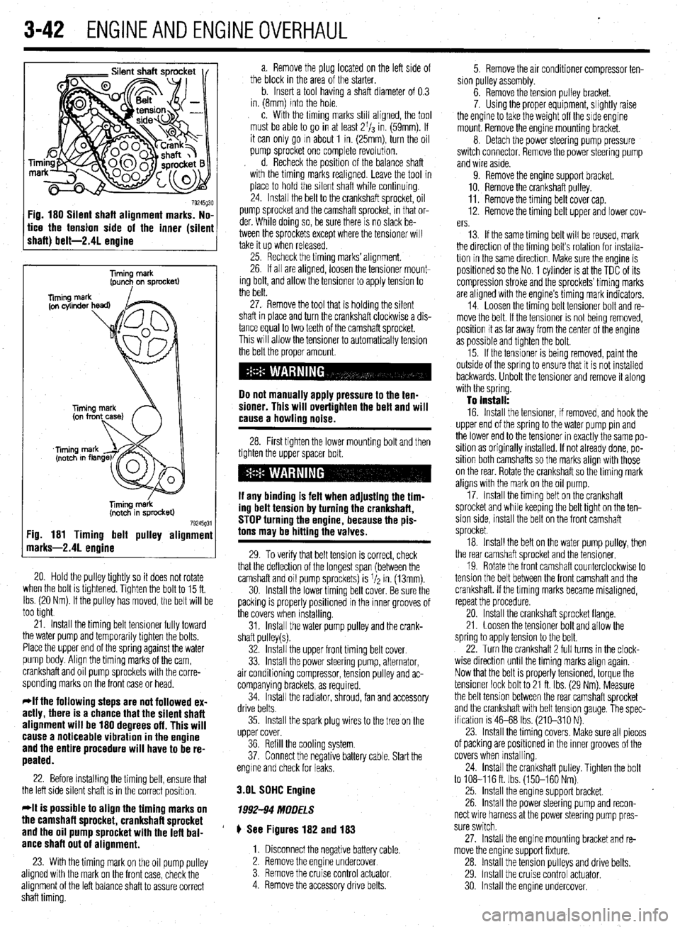
Fig. 180 Silent shaft alignment marks. No,
tice the tension side of the inner (silen
shaft) belt-2.41 enaine
Timing merk
(pun+ on sprocket)
liming m&k
(notch in sprocket)
79245g31 :ig. 181 Timing belt pulley alignmenl
narks-2.41 enoine
20. Hold the pulley tightly so it does not rotate
when the bolt is tlghtened. Tighten the bolt to 15 ft.
Ibs. (20 Nm). If the pulley has moved, the belt will be
too tight
21. Install the timing belt tensioner fully toward
the water pump and temporarily tighten the bolts.
Place the upper end of the spring against the water
pump body. Align the timing marks of the cam,
crankshaft and oil pump sprockets with the corre-
sponding marks on the front case or head.
*If the following steps are not followed ex-
actly, there is a chance that the silent shaft
alignment will be 180 degrees off. This will
cause a noticeable vibration in the engine
and the entire procedure will have to be re-
peated.
22. Before installing the timing belt, ensure that
the left side silent shaft is in the correct position.
*It is possible to align the timing marks on
the camshaft sprocket, crankshaft sprocket
and the oil pump sprocket with the lefl bal-
ance shaft out of alignment.
23. With the timing mark on the oil pump pulley
aligned with the mark on the front case, check the
alignment of the left balance shaft to assure correct
shaft timing. a. Remove the plug located on the left side of
the block in the area of the starter.
b. Insert a tool having a shaft diameter of 0.3
in. (8mm) into the hole.
c. With the timing marks still aligned, the tool
must be able to go in at least 2l/s in. (59mm). If
it can only go m about 1 in. (25mm), turn the oil
pump sprocket one complete revolution.
d. Recheck the position of the balance shaft
with the timing marks reahgned. Leave the tool in
place to hold the silent shaft while continuing.
24. Install the belt to the crankshaft sprocket, oil
pump sprocket and the camshaft sprocket, in that or-
der. While doing so, be sure there is no slack be-
tween the sprockets except where the tensioner will
take it up when released.
25. Recheck the timing marks’ alignment.
26. If all are aligned, loosen the tensioner mount-
ing bolt, and allow the tensioner to apply tension to
the belt.
27. Remove the tool that is holding the silent
shaft in place and turn the crankshaft clockwise a dis-
tance equal to two teeth of the camshaft sprocket.
This will allow the tensioner to automatically tension
the belt the proper amount.
Do not manually apply pressure to the ten-
sioner. This will overtighten the belt and will
cause a howling noise.
28. First tighten the lower mounting bolt and then
tighten the upper spacer bolt.
If any binding is felt when adiustino the tim-
ing delt tension by turning th;! crankshaft,
STOP turning the engine, because the pis-
tons may be hitting the valves.
29. To verify that belt tension is correct, check
that the deflection of the longest span (between the
camshaft and oil pump sprockets) is I/* in. (13mm).
30. Install the lower timing belt cover. Be sure the
packing is properly positioned in the inner grooves of
the covers when installing.
31. Install the water pump pulley and the crank-
shaft pulley(s).
32. Install the upper front timing belt cover.
33. Install the power steering pump, alternator,
air conditioning compressor, tension pulley and ac-
companying brackets, as required.
34. Install the radiator, shroud, fan and accessory
drive belts.
35. Install the spark plug wires to the tree on the
upper cover.
36. Refill the cooling system.
37. Connect the negative battery cable. Start the
engme and check for leaks.
3.OL SDHC Engine
1992-94 MODELS
# See Figures 182 and 183
1. Disconnect the negative battery cable.
2. Remove the engine undercover
3. Remove the cruise control
actuator 4. Remove the accessory drive belts. 5. Remove the air conditioner compressor ten-
sion pulley assembly.
6. Remove the tension pulley bracket.
7. Using the proper equipment, slightly raise
the engine to take the weight off the side engine
mount. Remove the engine mounting bracket.
8. Detach the power steering pump pressure
switch connector. Remove the power steering pump
and wire aside.
9. Remove the engine support bracket.
10. Remove the crankshaft pulley.
11. Remove the timing belt cover cap.
12. Remove the timing belt upper and lower cov-
ers.
13. If the same timing belt will be reused, mark
the direction of the timing belt’s rotation for installa-
tion in the same direction. Make sure the engine is
positioned so the No. 1 cylinder is at the TDC of its
compression stroke and the sprockets’ timing marks
are aligned with the engine’s timing mark indicators.
14. Loosen the timing belt tensioner bolt and re-
move the belt. If the tensioner is not being removed,
position it as far away from the center of the engine
as possible and tighten the bolt.
15. If the tensioner is being removed, paint the
outside of the spring to ensure that it is not installed
backwards. Unbolt the tensioner and remove it along
with the spring.
To install:
16. Install the tensioner, if removed, and hook the
upper end of the spring to the water pump pin and
the lower end to the tensioner in exactly the same po-
sition as originally installed. If not already done, po-
sition both camshafts so the marks align with those
on the rear. Rotate the crankshaft so the timing mark
aligns with the mark on the oil pump.
17. Install the timing belt on the crankshaft
sprocket and while keeping the belt tight on the ten-
sion side, install the belt on the front camshaft
sprocket.
18. Install the belt on the water pump pulley, then
the rear camshaft sprocket and the tensioner.
19. Rotate the front camshaft counterclockwise to
tension the belt between the front camshaft and the
crankshaft. If the tlmlng marks became misaligned,
repeat the procedure.
20. Install the crankshaft sprocket flange.
21. Loosen the tensioner bolt and allow the
spring to apply tension to the belt.
22. Turn the crankshaft 2 full turns in the clock-
wise direction until the timing marks align again.
Now that the belt is properly tensioned, torque the
tensioner lock bolt to 21 ft. Ibs. (29 Nm). Measure
the belt tension between the rear camshaft sprocket
and the crankshaft with belt tension gauge, The spec-
ification is 46-68 Ibs. (210-310 N).
23. Install the timing covers. Make sure all pieces
of packing are positioned in the inner grooves of the
covers when Installing.
24. install the crankshaft pulley. Tighten the bolt
to 108-116ft. Ibs. (150-160 Nm)
25. Install the engine support bracket.
26. Install the power steering pump and recon-
nect wire harness at the power steering pump pres-
sure switch.
27. Install the engine mounting bracket and re-
move the engine support fixture.
28. Install the tension pulleys and drive belts.
29. Install the cruise control actuator.
30 Install the engine undercover.
Page 111 of 408
.
3-50 ENGINEANDENGINEOVERHALJL
F
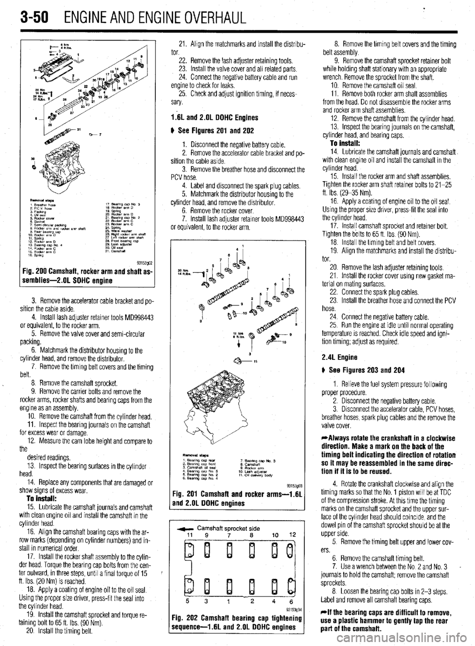
1 s 93153QO2 :ig. 200 Camshaft, rocker arm and shaft as-
iemblies-2.01 SOHC ermine
3. Remove the accelerator cable bracket and po-
sition the cable aside.
4. Install lash adjuster retainer tools MD998443
or equivalent, to the rocker arm.
5. Remove the valve cover and semi-circular
packing.
6. Matchmark the distributor housing to the
cylinder head, and remove the distributor,
7. Remove the timing belt covers and the timing
belt.
8 Remove the camshaft sprocket.
9. Remove the carrier bolts and remove the
rocker arms, rocker shafts and bearing caps from the
engine as an assembly.
10. Remove the camshaft from the cylinder head.
11. Inspect the bearing journals on the camshaft
for excess wear or damage.
12. Measure the cam lobe height and compare to
the
desired readings.
13. Inspect the bearing surfaces in the cylinder
head.
14. Replace any components that are damaged or
show signs of excess wear,
To install:
15. Lubricate the camshaft journals and camshaft
with clean engine oil and install the camshaft in the
cylinder head.
16. Align the camshaft bearing caps with the ar-
row marks (depending on cylinder numbers) and in-
stall in numerical order,
17. Install the rocker shaft assembly to the cylin-
der head. Torque the bearing cap bolts from the cen-
ter outward, in three steps, unh a final torque of 15
ft. Ibs. (20 Nm) is reached.
18. Apply a coating of engine oil to the oil seal.
Using the proper size driver, press-frt the seal into
the cylinder head.
19. install the camshaft sprocket and torque re-
taining bolt to 65 ft. Ibs. (90 Nm).
20. Install the timing belt. 21. Ahgn the matchmarks and install the distrrbu- 8. Remove the timing belt covers and the timing
tor. belt assembly.
22. Remove the lash adjuster retaining tools.
23. Install the valve cover and all related parts
24. Connect the negative battery cable and run
engine to check for leaks,
25. Check and adjust ignition timing, if neces-
sary.
l.‘6L and 2.lJL DOHC Engines
6 See Figures 201 and 202
1. Disconnect the negative battery cable.
2. Remove the accelerator cable bracket and po-
sition the cable aside.
3. Remove the breather hose and disconnect the
PCV hose. 9. Remove the camshaft sprocket retainer bolt
while holding shaft stationary with an appropriate
wrench. Remove the sprocket from the shaft.
10. Remove the camshaft oil seal.
11. Remove both rocker arm shaft assemblies
from the head. Do not drsassemble the rocker arms
and rocker arm shaft assemblies.
12. Remove the camshaft from the cylinder head.
13. inspect the bearing journals on the camshaft,
cylinder head, and bearing caps.
To install:
14. Lubricate the camshaft journals and camshaft
with clean engine oil and install the camshaft in the
cylinder head.
4. Label and disconnect the spark plug cables.
5. Matchmark the distributor housing to the
cylinder head, and remove the distributor.
6. Remove the rocker cover.
7. Install lash adjuster retarner tools MD998443
or equivalent, to the rocker arm. 15. Install the rocker arm and shaft assemblies.
Tighten the rocker arm shaft retainer bolts to 21-25
ft. Ibs. (2935 Nm).
16 Apply a coating of engine oil to the oil seal.
Using the proper size driver, press-fit the seal into
the cylinder head.
17. Instal! camshaft sprocket and retainer bolt.
Tighten the bolts to 65 ft. Ibs. (90 Nm).
18. Install the hming belt and belt covers.
19. Align the matchmarks and install the distribu-
tor.
93153gO: :ig. 201 Camshaft and rocker arms-i.61
rnd 2.OL DOHC engines
r ,
w Camshaft sprocket side
ei i i ij
20. Remove the lash adjuster retaining tools,
21. Install the rocker cover using new gasket ma-
terial on mating surfaces,
22. Connect the spark plug cables.
23. Install the breather hose and connect the PCV
hose.
24. Connect the negative battery cable.
25. Run the engme at idle until normal operating
temperature is reached. Check idle speed and igni-
tion timing; adjust as required.
2.4L Engine
) See Figures 203 and 204
1. Relieve the fuel system pressure following
proper procedure.
2. Disconnect the negative battery cable.
3. Disconnect the accelerator cable, PCV hoses,
breather hoses, spark plug cables and the remove the
valve cover.
*Always rotate the crankshaft in a clockwise
direction. Make a mark on the back of the
timing belt indicating the direction of rotation
so it may be reassembled in the same direc-
tion if it is to be reused.
4. Rotate the crankshaft clockwise and align the
timing marks so that the No. 1 piston will be at TDC
of the compression stroke. At this time the timing
marks on the camshaft sprocket and the upper sur-
face of the cyhnder head should coincide, and the
dowel pin of the camshaft sprocket should be at the
upper side.
5 Remove the timing belt upper and lower cov-
ers.
6. Remove the camshaft timing belt.
7. Use a wrench between the No 2 and No. 3
journals to hold the camshaft; remove the camshaft
sprockets.
8 Loosen the bearing cap bolts in 2-3 steps.
Label and remove all camshaft bearing caps,
*If the bearing caps are difficult to remove,
use a plastic hammer to gently tap the rear
part of the camshaft.
Page 112 of 408
ENGlNEANDENGlNEOVERHALiL 3-51
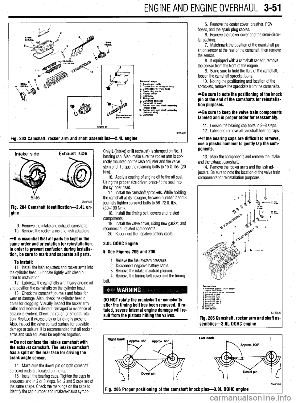
:ig. 203 Camshaft, rocker arm and shaft assemblies-2.41 engine 9315393'
Intake side Exhaust side
7923PG57 Fig. 204 Camshaft identification-2.41 en-
gine
9. Remove the intake and exhaust camshafts.
10. Remove the rocker arms and lash adjusters
*It is essential that all parts be kept in the
same order and orientation for reinstallation.
In order to prevent confusion during installa-
tion, be sure to mark and separate all parts.
To install:
11. Install the lash adjusters and rocker arms into
the cylinder head. Lubricate lightly with clean oil
prior to installation.
12. Lubricate the camshafts with heavy engine oil
and position the camshafts on the cylinder head.
13 Check the camshaft journals and lobes for
wear or damage. Also, check the cylinder head oil
holes for clogging. Visually inspect the rocker arm
roller and replace if dented, damaged or evidence of
seizure is evident. Check the roller for smooth rota-
tion. Replace If excess play or binding is present.
Also, inspect the valve contact surface for possible
damage or seizure. It is recommended that all rocker
arms and lash adjusters be replaced together.
*Do not confuse the intake camshaft with
the exhaust camshaft. The intake camshaft
has a split on the rear face for driving the ,
crank angle sensor.
14. Make sure the dowel pin on both camshaft
sprocket ends are located on the top.
15. Install the bearing caps. Tighten the caps in
sequence and rn 2 or 3 steps. No 2 and 5 caps are of
the same shape. Check the markings on the caps to
identify the cap number and intake/exhaust symbol. Only 1 (intake) or I? (exhaust) is stamped on No. 1
bearing cap Also, make sure the rocker arm is cor-
rectly mounted on the lash adjuster and the valve
stem end. Torque the retaining bolts to 15 ft. Ibs. (20
Nm).
16. Apply a coating of engine oil to the oil seal.
Using the proper size driver, press-fit the seal into
the cylinder head.
17. Install the camshaft sprockets. While holding
the camshaft at its hexagon, between number 2 and 3
journals tighten sprocket bolts to 58-72 ft. Ibs.
(80-l 00 Nm).
18. Install the timing belt, covers and related
components.
19. Install the valve cover, using new gasket, and
reconnect all related components
20. Reconnect the negative battery cable.
3.OL DOHC Engine
# See Figures 205 and 206
1. Relieve the fuel system pressure.
2. Disconnect negative battery cable.
3. Remove the intake manifold plenum.
4. Remove the timing belt cover and the timing
belt.
DO NOT rotate the crankshaft or camshafts
after the timing belt has been removed. If ro-
tated, severe internal engine damage will re-
sult from the pistons hitting the valves.
5. Remove the center cover, breather, PCV
hoses, and the spark plug cables.
6. Remove the rocker cover and the semi-circu-
lar packing.
7. Matchmark the position of the crankshaft po-
sition sensor at the rear of the camshaft, then remove
the sensor.
8. If equipped with a camshaft sensor, remove
the sensor from the front of the engine.
9 Being sure to hold the flats of the camshaft,
loosen the camshaft sprocket bolts.
10. Noting the positionmg and location of the
sprockets, remove the sprockets from the camshafts.
*Be sure to note the positioning of the knock
pin at the end of the camshafts for reinstalla-
tion purposes.
*Be sure to keep the valve train components
labeled and in proper order for reassembly.
11. Loosen the bearing cap bolts in 2-3 steps.
12. Label and remove all camshaft bearing caps.
*If the bearing caps are difficult to remove,
use a plastic hammer to gently tap the com-
ponents.
13. Mark the components and remove the intake
and the exhaust camshafts.
14. Remove the rocker arms and the lash ad-
justers. Be sure to note the location of the valve train
components for reinstallation purposes.
1 semblies-3.01 DOHC engine
I
Left bank
7923PG58 Fig. 206 Proper positioning of the camshaft knock pins-3.01 DOHC engine
Page 115 of 408
3-54 ENGINEANDENGINEOVERHALJL
from the, access may be possible (though a little
awkward) to measure the camshaft lobes using a mi-
crometer
In any case, two measurements are necessary for
each lobe. Measurement Y or the total LOBE HEIGHT
and measurement X or the total LOBE WIDTH. To
find the lobe lift, you simply subtract X from Y (sub-
tract the width from the height).
Note each measurement, then make your calcula-
tion to determine the lift. Note the final results and re-
peat the process on the remaining camshaft lobes.
Finally, you should compare your results to the spec-
ifications charts and decide if a new camshaft is in
your future.
REMOVAL &INSTALLATION
2.OL and 2.4L Engines
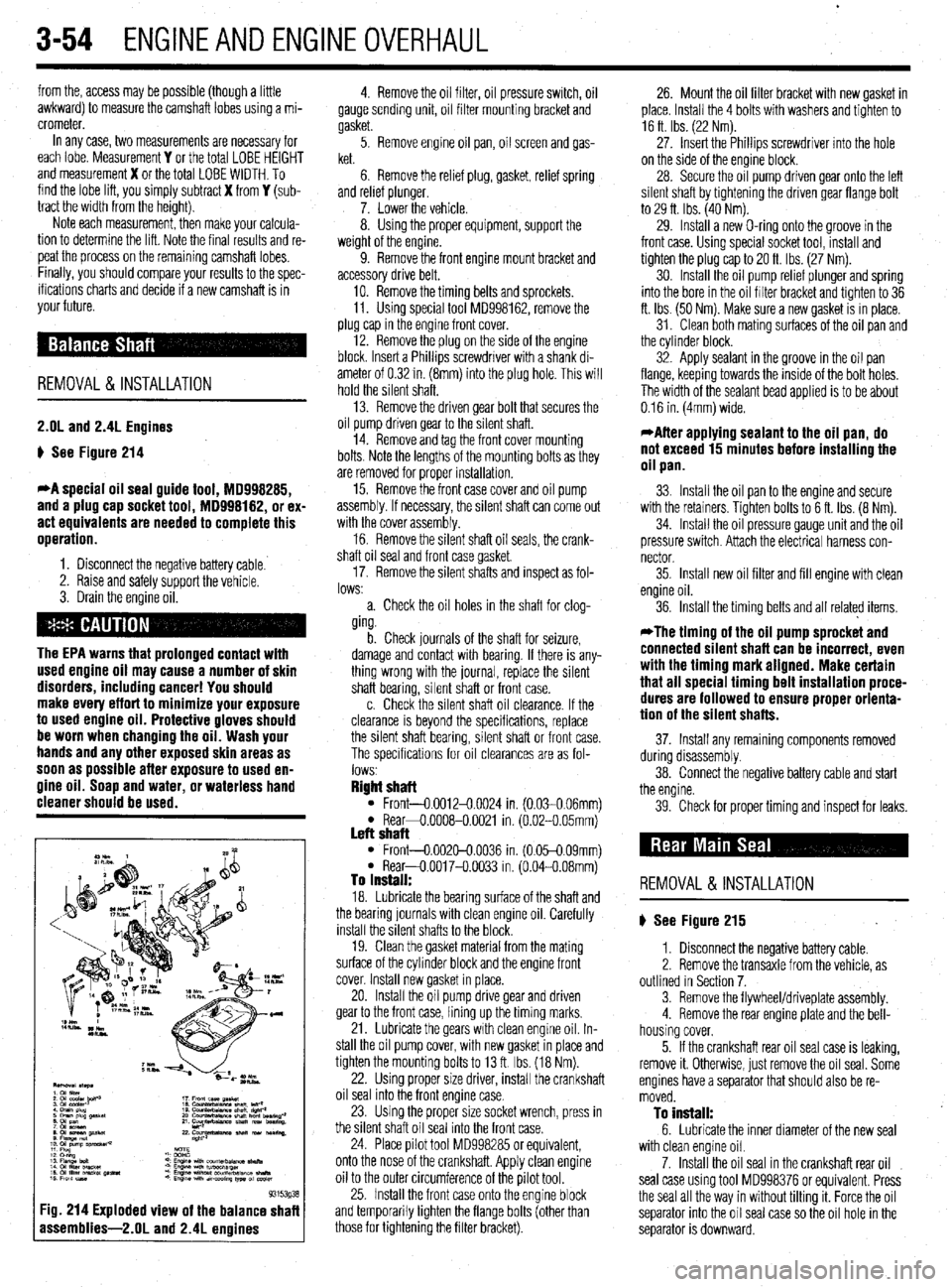
p See Figure 214
*A special oil seal guide tool, 18998285,
and a plug cap socket tool, MD998182, or ex-
act equivalents are needed to complete this
operation.
1. Disconnect the negative battery cable.
2. Raise and safely support the vehicle.
3. Drain the engine oil.
The EPA warns that prolonged contact with
used engine oil may cause a number of skin
disorders, including cancer! You should
make every effort to minimize your exposure
to used engine oil. Protective gloves should
be worn when changing the oil. Wash your
hands and any other exposed skin areas as
soon as possible after exposure to used en-
gine oil. Soap and water, or waterless hand
cleaner should be used.
93153g3
:ig. 214 Exploded view of the balance shaf
assemblies-2.01 and 2.4L enoines
4. Remove the oil filter, oil pressure switch, oil
gauge sending unit, oil filter mounting bracket and
gasket.
5. Remove engine oil pan, oil screen and gas-
ket.
6. Remove the relief plug, gasket, relief spring
and relref plunger.
7. Lower the vehicle.
8. Using the proper equipment, support the
weight of the engine.
9. Remove the front engine mount bracket and
accessory drive belt,
10. Remove the timing belts and sprockets.
11. Using special tool MD998162, remove the
plug cap in the engine front cover.
12. Remove the plug on the side of the engine
block. Insert a Phillips screwdriver with a shank di-
ameter of 0.32 in. (8mm) into the plug hole. This will
hold the silent shaft.
13. Remove the driven gear bolt that secures the
oil pump driven gear to the silent shaft.
14. Remove and tag the front cover mounting
bolts. Note the lengths of the mounting bolts as they
are removed for proper installation.
15. Remove the front case cover and oil pump
assembly. If necessary, the silent shaft can come out
with the cover assembly.
16. Remove the silent shaft oil seals, the crank-
shaft oil seal and front case gasket
17. Remove the silent shafts and inspect as fol-
lows:
a. Check the oil holes in the shaft for clog-
ging.
b. Check journals of the shaft for seizure,
damage and contact with bearing. If there is any-
thing wrong with the journal, replace the silent
shaft bearing, silent shaft or front case.
c. Check the silent shaft oil clearance. If the
clearance is beyond the specifications, replace
the silent shaft bearing, silent shaft or front case.
The specifications for oil clearances are as fol-
lows
Right shaft l Front-0.0012-0.0024 in. (0.030.06mml l Rear+0.0008-0.0021 in. (6.02-O 05mm) Left shaft l Front-0.002&0.0036 in. (0.05-0.09mm) l Rear-O.0017-O.0033 in. (0.04-0.08mm) To install: 18. Lubricate the bearing surface of the shaft and
the bearing journals with clean engine oil. Carefully
install the silent shafts to the block.
19. Clean the gasket material from the mating
surface of the cylinder block and the engine front
cover. Install new gasket in place.
20. Install the oil pump drive gear and driven
gear to the front case, lining up the timing marks.
21. Lubricate the gears with clean engine oil. In-
stall the oil pump cover, with new gasket in place and
tighten the mounting bolts to 13 ft. Ibs. (18 Nm).
22. Using proper size driver, install the crankshaft
oil seal into the front engine case.
23. Using the proper size socket wrench, press in
the silent shaft oil seal into the front case.
24. Place pilot tool MD998285 or equivalent,
onto the nose of the crankshaft. Apply clean engine
oil to the outer circumference of the pilot tool.
25. Install the front case onto the engine block
and temporarily tighten the flange bolts (other than
those for tightening the filter bracket). 26. Mount the oil filter bracket with new gasket in
place. Install the 4 bolts with washers and tighten to
16 ft Ibs. (22 Nm).
27. Insert the Phillips screwdriver into the hole
on the side of the engine block.
28. Secure the oil pump driven gear onto the left
silent shaft by tightening the driven gear flange bolt
to 29 ft. Ibs. (40 Nm).
29. Install a new O-ring onto the groove in the
front case. Using special socket tool, install and
tighten the plug cap to 20 ft. Ibs (27 Nm).
30. Install the oil pump relief plunger and spring
into the bore in the oil filter bracket and tighten to 36
ft. Ibs. (50 Nm). Make sure a new gasket is in place.
31. Clean both mating surfaces of the oil pan and
the cylinder block.
32. Apply sealant in the groove in the oil pan
flange, keeping towards the inside of the bolt holes.
The width of the sealant bead applied is to be about
0.16 in. (4mm) wide.
*After applying sealant to the oil pan, do
not exceed 15 minutes before installing the
oil pan.
33. Install the oil pan to the engine and secure
with the retainers. Tighten bolts to 6 ft. Ibs. (8 Nm).
34. Install the oil pressure gauge unit and the oil
pressure switch. Attach the electrical harness con-
nector
35. Install new oil filter and fill engine with clean
engine oil.
36. Install the timing belts and all related items,
*The timing of the oil pump sprocket and
connected silent shaft can be incorrect, even
with the timing mark aligned. Make certain
that all special timing belt installation proce-
dures are followed to ensure proper orienta-
tion of the silent shafts.
37. Install any remaining components removed
during disassembly.
38. Connect the negative battery cable and start
the engine.
39. Check for proper timing and inspect for leaks.
REMOVAL &INSTALLATION
p See Figure 215
1. Disconnect the negative battery cable.
2. Remove the transaxle from the vehicle, as
outlined in Section 7.
3. Remove the flywheel/driveplate assembly.
4. Remove the rear engine plate and the bell-
housing cover.
5. If the crankshaft rear oil seal case is leaking,
remove it. Otherwise, just remove the oil seal. Some
engines have a separator that should also be re-
moved.
To install: 6. Lubricate the inner diameter of the new seal
with clean engine oil.
7. Install the oil seal in the crankshaft rear oil
seal case using tool MD998376 or equivalent. Press
the seal all the way in without tilting it. Force the oil
separator into the oil seal case so the oil hole in the
separator is downward.
Page 116 of 408
ENGINEANDENGINEOVERHAUL 3-55
8. Run a bead of sealer along any seams be-
tween the seal case and block. Install the seal case
with a new gasket.
9. Install the flywheel/driveplate and transaxle.
10. Connect the negative battery cable and check
for leaks.
11. Adjust oil level as necessary.
REMOVAL &INSTALLATION To lnstell:
7. Coat the threads of the driveplate/flywheel re-
taining bolts with thread locking compound.
8. Position the driveplatelflywheel on the crank-
shaft flange.
9. On automatic transaxle equipped models, in-
stall the driveplate adapter.
10. Install and tighten the bolts, in a alternating
star pattern, to the following specifications:
l 1.5L engine: 98 ft. Ibs. (135 Nm) l 1.6L, 2.01 and 2.4L engines: 94-101 ft.
Ibs. (130-140 Nm)
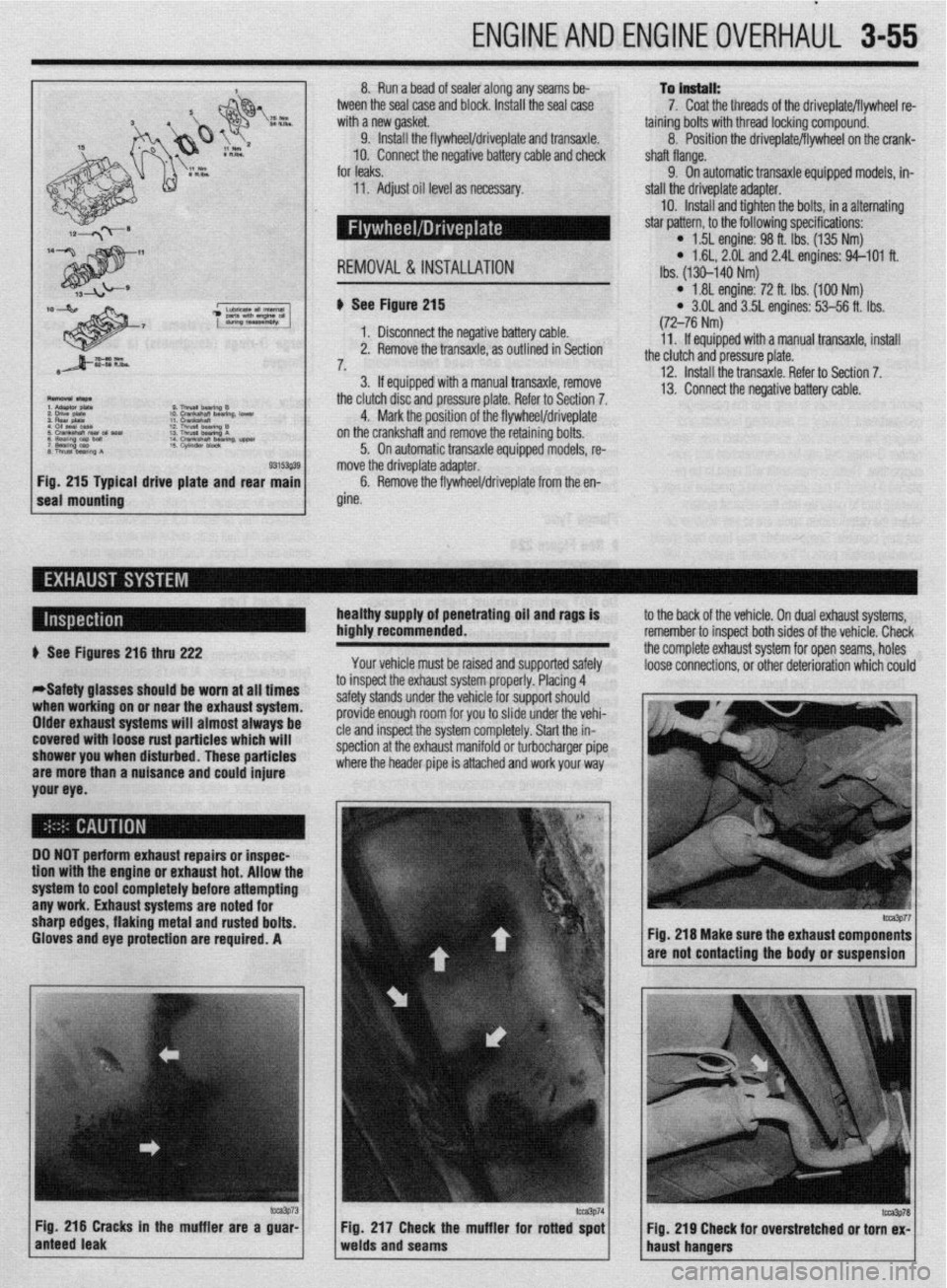
al drive plate and rear b See Figure 215
1. Disconnect the negative battery cable.
2. Remove the transaxle, as outlined in Section
7,
3. If equipped with a manual transaxle, remove
the clutch disc and pressure plate. Refer to Section 7.
4. Mark the position of the flywheel/driveplate
on the crankshaft and remove the retaining bolts.
5. On automatic transaxle equipped models, re-
move the driveplate adapter.
6. Remove the flywheel/driveplate from the en-
gine.
l 1.81 engine: 72 ft. Ibs. (100 Nm) l 3.OL and 3.5L engines: 53-56 ft. Ibs.
(72-76 Nm)
11. If equipped with a manual transaxle, install
the clutch and pressure plate.
12. Install the transaxle. Refer to Section 7.
13. Connect the negative battery cable.
healthy supply of penetrating oil and rags is
highly recommended.
Your vehicle must be raised and supported safely to the back of the vehicle. On dual exhaust systems,
remember to insoect both sides of the vehicle. Check
the complete exhaust system for open seams, holes
loose connections, or other deterioration which could + See Figures 216 thru 222
*Safety glasses should be worn at all times
when working on or near the exhaust system.
Older exhaust systems will almost always be
covered with loose rust particles which will
shower you when disturbed. These particles
are more than a nuisance and could injure
your eye. to inspect the exhaust system properly. Placing 4
safety stands under the vehicle for support should
provide enough room for you to slide under the vehi-
cle and inspect the system completely. Start the in-
spection at the exhaust manifold or turbocharger pipe
where the header pipe is attached and work your way
DO NOT perform exhaust repairs or inspec-
tion wtth the engine or exhaust hot. Allow thr
system to cool completely before attempting
any work. Exhaust systems are noted for
sharp edges, flaking metal and rusted bolts.
Gloves and eye protection are required. A
m3p73 Fig. 216 Cracks in the muffler are a guar-
anteed leak Fig 217 Check the muffler for rotted spot
Fig. 219 Cheek for overstretched or torn ex-
welds and seams
haust hangers
fm3p77 Fig. 216 Make sure the exhaust components
are not contacting the body or suspension
lcca3P78