1900 MITSUBISHI DIAMANTE oil pressure
[x] Cancel search: oil pressurePage 195 of 408
5-8 FUELSYSTEM
9 ,npimr w1m.m
1: i”“L,
1: 82”w
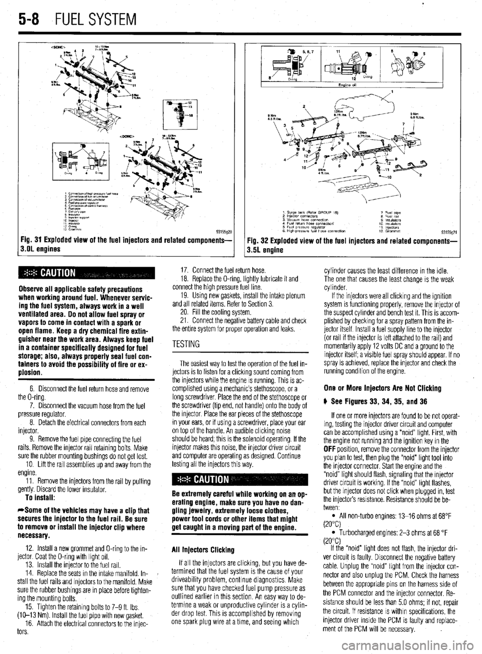
93155gx Fig. 31 Exploded view of the fuel injectors and related components-
s.OL engines
Observe all applicable safety precautions
when working around fuel. Whenever servic-
ing the fuel system, always work in a well
ventilated area. Do not allow fuel spray or
vapors to come in contact with a spark or
open flame. Keep a dry chemical fire extin-
guisher near the work area. Always keep fuel
in a container specifically designed for fuel
storage; also, always properly seal fuel con-
tainers to avoid the possibility of fire or ex-
plosion.
6. Disconnect the fuel return hose and remove
the O-ring.
7. Disconnect the vacuum hose from the fuel
pressure regulator.
8. Detach the electrical connectors from each
injector.
9. Remove the fuel pipe connectmg the fuel
rails. Remove the injector rail retaining bolts. Make
sure the rubber mounting bushings do not get lost.
10. Lift the rail assemblies up and away from the
engine.
11. Remove the injectors from the rail by pulling
gently. Discard the lower insulator.
To install:
*Some of the vehicles may have a clip that
secures the injector to the fuel rail. Be sure
to remove or install the injector clip where
necessary.
12. Install a new grommet and O-ring to the in-
jector. Coat the O-ring with light oil.
13. Install the injector to the fuel rail.
14. Replace the seats in the intake manifold. In-
stall the fuel rails and injectors to the manifold. Make
sure the rubber bushings are in place before tighten-
ing the mounting bolts.
15. Tighten the retaining bolts to 7-9 ft. Ibs.
(W-13 Nm) Install the fuel pipe with new gasket.
16. Attach the electrical connectors to the injec-
tors
Fig. 32 Exploded view of the fuel injectors and related components-
3.5L engine
17. Connect the fuel return hose.
18. Replace the O-ring, lightly lubricate it and
connect the high pressure fuel line.
19. Usmg new gaskets, install the intake plenum
and all related items. Refer to Section 3.
20. Fill the cooling system.
21. Connect the negative battery cable and check
the entire system for proper operation and leaks.
The easiest way to test the operation of the fuel in-
jectors is to listen for a clicking sound coming from
the injectors while the engine IS running. This is ac-
complished using a mechanic’s stethoscope, or a
long screwdriver. Place the end of the stethoscope or
the screwdriver (tip end, not handle) onto the body of
the injector. Place the ear pieces of the stethoscope
in your ears, or if using a screwdriver, place your ear
on top of the handle. An audible chcking noise
should be heard; this is the solenoid operating. If the
injector makes this noise, the injector driver circuit
and computer are operating as designed. Continue
testing all the injectors this way.
Be extremely careful while working on an op-
erating engine, make sure you have no dan-
gling jewelry, extremely loose clothes,
power tool cords or other items that might
get caught in a moving part of the ermine.
All Injectors Clicking
If all the injectors are clicking, but you have de-
termined that the fuel system is the cause of your
driveability problem, continue diagnostics. Make
sure that you have checked fuel pump pressure as
outlined earlier in this section. An easy way to de-
termine a weak or unproductive cylinder is a cylin-
der drop test. This is accomplished by removing
one spark plug wire at a time, and seeing which cylinder causes the least difference in the idle.
The one that causes the least change is the weak
cylinder.
If the injectors were all clicking and the ignition
system is functioning properly, remove the injector of
the suspect cylinder and bench test it. This is accom-
plished by checking for a spray pattern from the in-
jector itself Install a fuel supply line to the injector
(or rail if the injector is left attached to the rail) and
momentarily apply 12 volts DC and a ground to the
injector itself; a visible fuel spray should appear. If no
spray is achieved, replace the injector and check the
running condition of the engine.
One or More Injectors Are Not Clicking
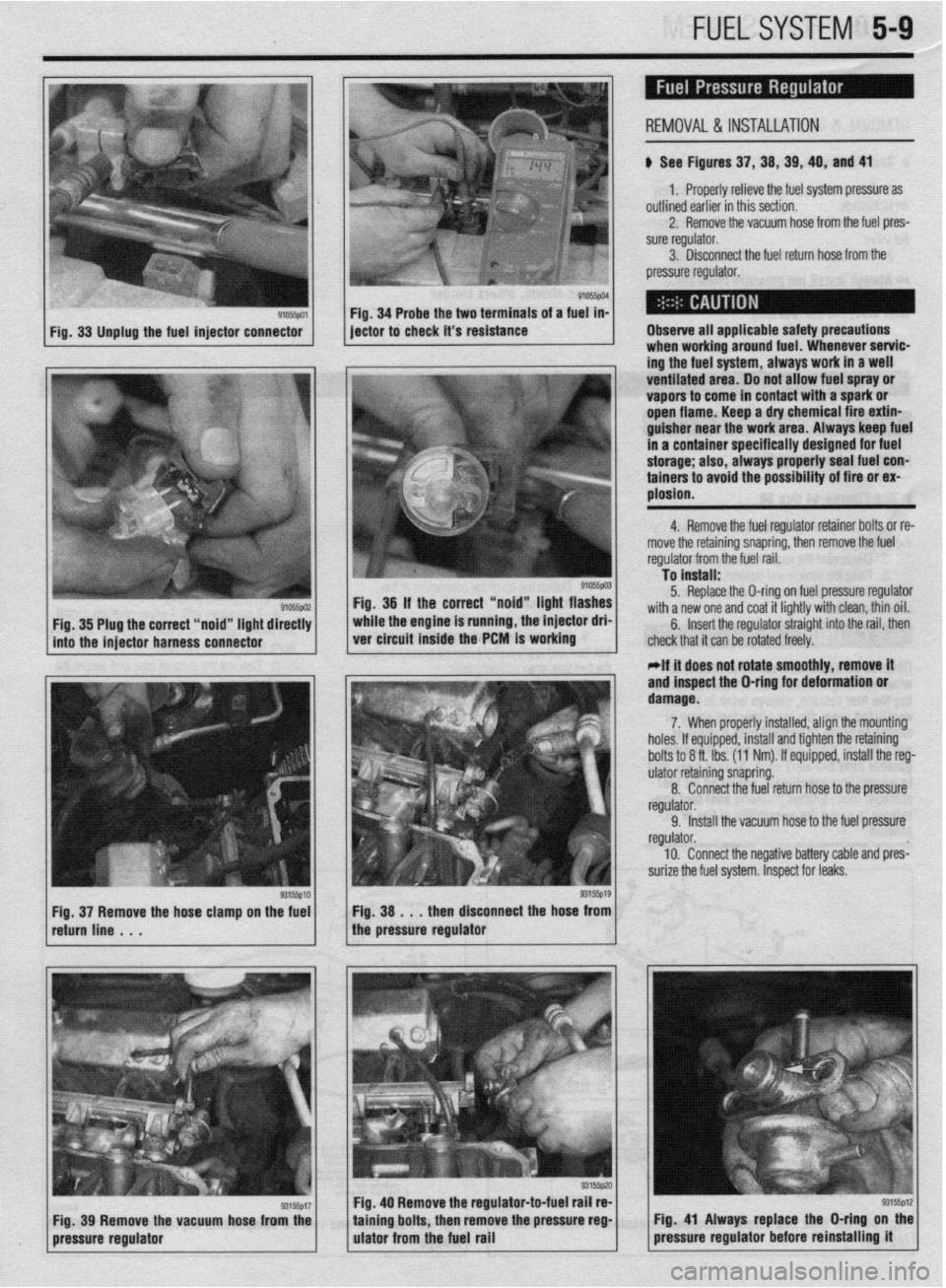
6 See Figures 33, 34, 35, and 36
If one or more injectors are found to be not operat-
ing, testing the injector driver circuit and computer
can be accomplished using a “noid” light. First, with
the engine not running and the ignition key in the
OFF position, remove the connector from the injector
you plan to test, then plug the “noid” light tool into
the injector connector. Start the engine and the
“noid” light should flash, signaling that the injector
driver circuit is working. If the “noid” light flashes,
but the injector does not click when plugged in, test
the injectors resistance. Resistance should be be-
tween:
l All non-turbo engines: 13-16 ohms at 68°F
(20°C)
l Turbocharged engines: 2-3 ohms at 68 “F
(20°C)
If the “noid” light does not flash, the injector dri-
ver circuit is faulty. Disconnect the negative battery
cable. Unplug the “noid” light from the injector con-
nector and also unplug the PCM. Check the harness
between the appropriate pins on the harness side of
the PCM connector and the injector connector. Re-
sistance should be less than 5.0 ohms; if not, repair
the circuit. If resistance
IS within specifications, the
injector driver inside the PCM is faulty and replace-
ment of the PCM will be necessary.
Page 196 of 408
FUELSYSTEM 5-9
p See Figures 37, 38, 39, 49, and 41
REMOVAL& INSTALLATION
1. Properly relieve the fuel system pressure as
outlined earlier in this section.
2. Remove the vacuum hose from the fuel pres-
sure regulator.
3. Disconnect the fuel return hose from the
pressure regulator.
Fig. 33 Unplug the fuel injector connector
, Observe all applicable safety precautions
when working around fuel. Whenever servic-
ing the fuel system, always work in a well
ventilated area. Do not apow fuel spray or
vapors to come in contact with a spark or
open flame. Keep a dry chemical fire extin-
guisher near the work area. Always keep fuel
in a container specifically designed for fuel
storage; also, always properly seal fuel con-
tainers to avoid the possibility of fire or ex-
plosion.
I ,“~“*I.“. ..-.. * . ..” ._“. .-... To install:
I
Fig. 36 If the correct “noid” light flashes
while the engine is running, the injector dri-
ver circuit inside the PCM is working 5. Replace the O-ring on fuel pressure regulator
with a new one and coat it lightly with clean, thin oil.
6. Insert the regulator straight into the rail, then
chl . . . . . * * . . , .
xk mat n can oe rorarea rreery. 4. Remove the fuel regulator retainer bolts or re-
move the retaining snapring, then remove the fuel rrwkdnr frnm the fl~el rail
91055pu2 Fig. 35 Plug the correct “noid” light directly
into the iniector harness connector
I I I , r,
If it does not rotate smoothly, remove it
and inspect the O-ring for deformation or
damage.
7. When properly installed, align the mounting
holes. If equipped, install and tighten the retaining
bolts to 8 ft. Ibs. (11 Nm). If equipped, install the reg-
ulator retaining snapring.
8. Connect the fuel return hose to the pressure
regulator.
9. Install the vacuum hose to the fuel pressure
regulator.
10. Connect the negative battery cable and pres-
surize the fuel system. Inspect for leaks.
1 ret;rnline ~ . . g315sp10 1 1 ~~~.~~~s~~~~~u~s,“p”“““’ the hose? 1 Fig 37 Remove the hose clamp on the fuel
Fig. 39 Remove the vacuum hose from the
pressure regulator Fig. 40 Remove the regulator-to-fuel rail re-
taining bolts, then remove the pressure reg-
ulator from the fuel rail
Page 205 of 408
6-2 CHASSIS ELECTRICAL
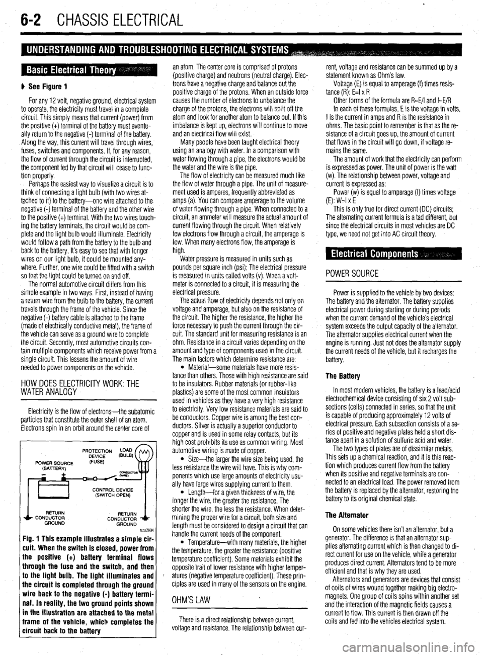
) See Figure 1
For any 12 volt, negative ground, electrical system
to operate, the electricity must travel in a complete
circurt. This simply means that current (power) from
the posibve (t) terminal of the battery must eventu-
ally return to the negative (-) terminal of the battery.
Along the way, this current will travel through wires,
fuses, switches and components. If, for any reason,
the flow of current through the circuit is interrupted,
the component fed by that circuit will cease to func-
tion properly.
Perhaps the easiest way to visualize a circuit is to
think of connecting a light bulb (with two wires at-
tached to it) to the battery-one wire attached to the
negative (-) terminal of the battery and the other wire
to the positive (t) terminal. With the two wires touch-
ing the battery terminals, the circuit would be com-
plete and the light bulb would illummate. Electricity
would follow a path from the battery to the bulb and
back to the battery. It’s easy to see that wrth longer
wires on our light bulb, it could be mounted any-
where. Further, one wire could be fitted with a switch
so that the light could be turned on and off.
The normal automotive circuit differs from this
simple example in two ways, Frrst, instead of having
a return wire from the bulb to the battery, the current
travels through the frame of the vehicle. Since the
negative (-) battery cable is attached to the frame
(made of electrically conductive metal), the frame of
the vehicle can serve as a ground wire to complete
the circuit. Secondly, most automotive circuits con-
tain multiple components which receive power from a
single circuit. This lessens the amount of wire
needed to power components on the vehicle.
HOW DOES ELECTRlClTYWORK:THE
WATER ANALOGY
Electricity is the flow of electrons-the subatomic
particles that constitute the outer shell of an atom.
Electrons spin in an orbit around the center core of
RETURN
RETURN
CONDUCTOR
CONDUCTOR
GROUND
GROUND
lccs2w
Fig. 1 This example illustrates a simple cir-
cuit. When the switch is closed, power from
the positive (t) battery terminal flows
through the fuse and the switch, and then
to the light bulb. The light illuminates and
the circuit is completed through the ground
wire back to the negative (-) battery termi-
nal. In reality, the two ground points shown
in the illustration are attached to the metal
frame of the vehicle, which completes the
circuit back to the battery
an atom The center core is comprised of protons
(positive charge) and neutrons (neutral charge). Elec-
trons have a negative charge and balance
out the
positive charge of the protons. When an outside force
causes the number of electrons to unbalance the
charge of the protons, the electrons will split off the
atom and look for another atom to balance out. If this
imbalance is kept up, electrons will continue to move
and an electrical flow will exist.
Many people have been taught electrical theory
using an analogy with water. In a comparison wrth
water flowing through a pipe, the electrons would be
the water and the wire is the pipe.
The flow of electricity can be measured much like
the flow of water through a pipe. The unit of measure-
ment used is amperes, frequently abbreviated as
amps (a). You can compare amperage to the volume
of water flowing through a pipe. When connected to a
circuit, an ammeter WIII measure the actual amount of
current flowing through the circuit. When relatively
few electrons flow through a circuit, the amperage is
low. When many electrons flow, the amperage is
high.
Water pressure is measured in units such as
pounds per square inch (psi); The electrical pressure
is measured in unrts called volts (v). When a volt-
meter is connected to a circuit, it is measuring the
electrical pressure.
The actual flow of electricity depends not only on
voltage and amperage, but also on the resistance of
the circuit The higher the resistance, the higher the
force necessary to push the current through the cir-
cuit. The standard unit for measuring resistance is an
ohm. Resistance in a crrcuit varies dependmg on the
amount and type of components used in the circuit.
The main factors which determine resistance are:
l Material-some materials have more resis-
tance than others Those with high resistance are said
to be insulators Rubber materials (or rubber-like
plashcs) are some of the most common insulators
used in vehicles as they have a very high resistance
to electricity Very low resistance materials are said to
be conductors. Copper wire is among the best con-
ductors. Silver is actually a superior conductor to
copper and is used in some relay contacts, but its
high cost prohibits its use as common wiring Most
automotive wiring is made of copper.
l Size-the larger the wire size being used, the
less resistance the wire will have. This IS why com-
ponents which use large amounts of electricity usu-
ally have large wires supplying current to them.
l Length-for a given thickness of wire, the
longer the wire, the greater the resistance. The
shorter the wire, the less the resistance. When deter-
mining the proper wire for a circuit, both size and
length must be considered to design a circuit that can
handle the current needs of the component.
l Temperature-with many materials, the higher
the temperature, the greater the resistance (positive
temperature coefficient). Some materials exhibit the
opposite trait of lower resistance with higher temper-
atures (negative temperature coefficient). These prin-
ciples are used in many of the sensors on the engine
OHM'S LAW
There is a direct relationship between current,
voltage and resistance. The relationship between cur- rent, voltage and resistance can be summed up by a
statement known as Ohm’s law.
Voltage (E) is equal to amperage (I) times resis-
tance (R): E=l x R
Other forms of the formula are R=E/I and I=E/R
In each of these formulas, E is the voltage in volts,
I is the current in amps and R IS the resistance in
ohms. The basic point to remember is that as the re-
sistance of a circuit goes up, the amount of current
that flows in the circuit will go down, if voltage re-
mains the same.
The amount of work that the electricity can perform
is expressed as power. The unit of power is the watt
(w). The relationship between power, voltage and
current
IS expressed as:
Power(w) is equal to amperage (I) times voltage
(E): W=l x E
This is only true for direct current (DC) circuits:
The alternating current formula is a tad different, but
since the electrical circuits in most vehicles are DC
type, we need not get into AC circuit theory.
POWERSOURCE
Power is supplied to the vehicle by two devices:
The battery and the alternator. The battery supplies
electrical power during starting or during periods
when the current demand of the vehicle’s electrical
system exceeds the output capacity of the alternator.
The alternator supplies electrical current when the
engine is running
Just not does the alternator supply
the current needs of the vehicle, but it recharges the
battery.
The Battery
In most modern vehicles, the battery is a lead/acid
electrochemical device consisting of six 2 volt sub-
sections (cells) connected in series, so that the unit
is capable of producing approximately 12 volts of
electrical pressure. Each subsection consists of a se-
ries of positive and negative plates held a short dis-
tance apart in a solutron of sulfuric acid and water.
The two types of plates are of dissimilar metals,
This sets up a chemrcal reaction, and it is this reac-
tion which produces current flow from the battery
when Its positive and negattve terminals are con-
nected to an electrical load. The power removed from
the battery is replaced by the alternator, restoring the
battery to its original chemical state.
The Alternator
On some vehicles there isn’t an alternator, but a
generator. The difference IS that an alternator sup-
plies alternating current which is then changed to di-
rect current for
use on the vehicle, while a generator
produces direct current. Alternators tend to be more
efficient and that is why they are used.
Alternators and generators are devices that consist
of coils of wires wound together making big electro-
magnets. One group of coils spins within another set
and the interaction of the magnetic fields causes a
current to flow. This current is then drawn off the
coils and fed into the vehicles electrical system.
Page 293 of 408
7-14 DRIVETRAIN
The only model covered by this manual equipped
with a transfer case is the 1990-93 AWD Galant. assembly. Place a drain pan under the rear of the
transfer assembly to catch any fluid that leaks out.
3. Usinq a flat-bladed prying tool, carefully re-
REMOVAL &INSTALLATION
move the ofi seal from the transfer dust seal guard
To install: 4. Using proper size seal driver tool, install the
seal into the dust seal quard and the transfer assem-
blv.
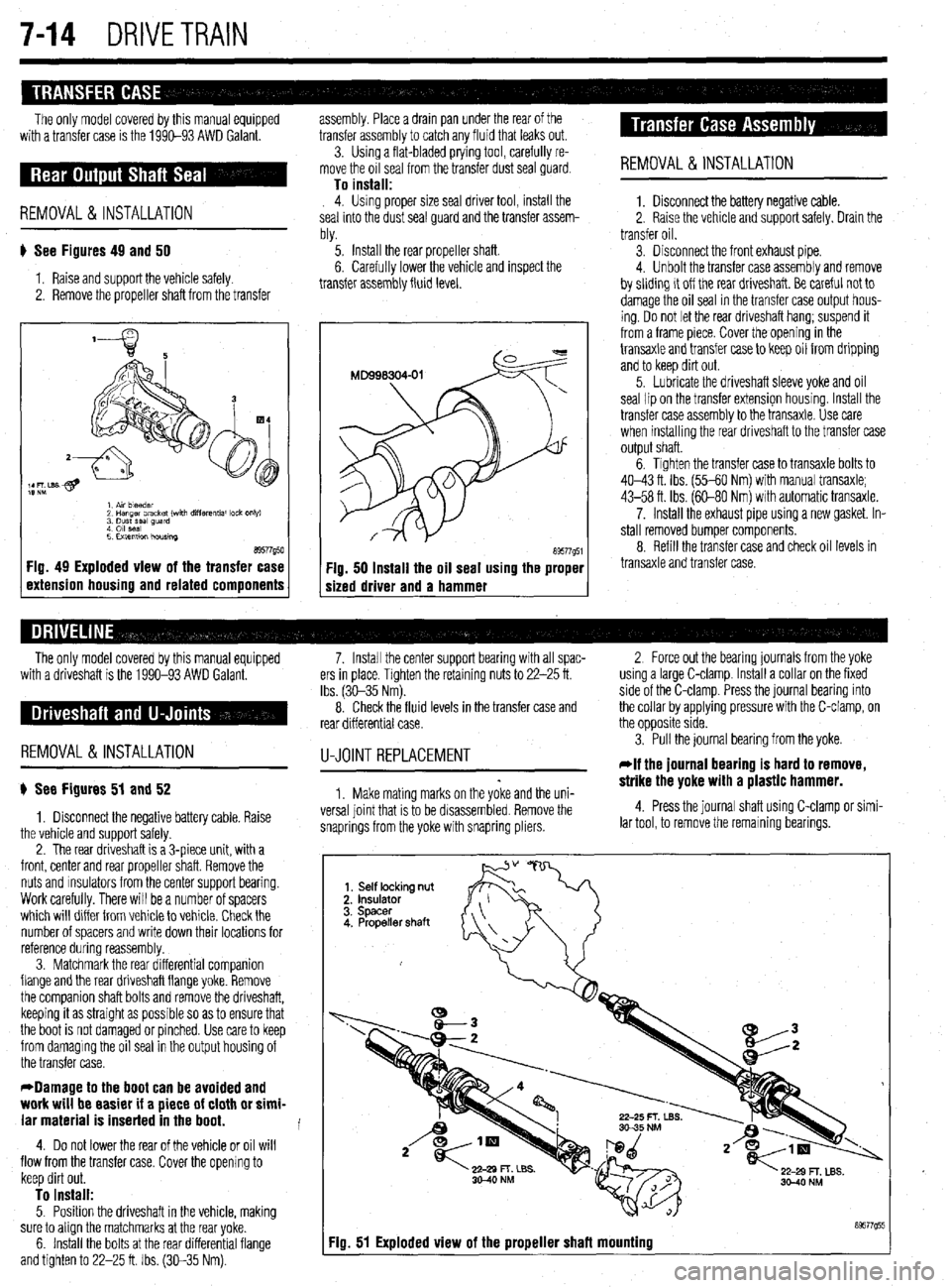
# See Figures 49 and 50
1. Raise and support the vehicle safely.
2. Remove the propeller shaft from the transfer ‘5. Install the rear propeller shaft.
6. Carefully lower the vehicle and inspect the
transfer assembly fluid level.
a9577g50 1 Fig. 49 Exploded view of the transfer case
1 extension housing and related components a9577g51 Fig. 50 Install the oil seal using the proper
sized driver and a hammer REMOVAL &INSTALLATION
1. Disconnect the battery negative cable.
2. Raise the vehicle and support safely. Drain the
transfer oil.
3. Disconnect the front exhaust pipe.
4. Unbolt the transfer case assembly and remove
by sliding it off the rear driveshaft. Be careful not to
damage the oil seal in the transfer case output hous-
ing. Do not let the rear driveshaft hang; suspend it
from a frame piece. Cover the opening in the
transaxle and transfer case to keep oil from dripping
and to keep dirt out.
5. Lubricate the driveshaft sleeve yoke and oil
seal lipan the transfer extension housing. Install the
transfer case assembly to the transaxle. Use care
when installing the rear driveshaft to the transfer case
output shaft.
6. Tighten the transfer case to transaxle bolts to
40-43 ft. Ibs. (55-60 Nm) with manual transaxle;
43-58 ft. Ibs. (60-80 Nm) with automatic transaxle.
7. Install the exhaust pipe using a new gasket. In-
stall removed bumper components.
8. Refill the transfer case and check oil levels in
transaxle and transfer case.
The only model covered by this manual equipped
with a driveshaft is the 1990-93 AWD Galant.
REMOVAL &INSTALLATION
) See Figures 51 and 52
1. Disconnect the negative battery cable. Raise
the vehicle and support safely.
2. The rear driveshaft is a 3-piece unit, with a
front, center and rear propeller shaft. Remove the
nuts and msulators from the center support bearing.
Work carefully. There will be a number of spacers
which will differ from vehicle to vehicle. Check the
number of spacers and write down their locations for
reference during reassembly.
3. Matchmark the rear differential companion
flange and the rear driveshaft flange yoke. Remove
the companion shaft bolts and remove the driveshaft,
keeping it as straight as possible so as to ensure that
the boot is not damaged or pinched. Use care to keep
from damaging the oil seal in the output housing of
the transfer case.
*Damage to the boot can be avoided and
work will be easier if a piece of cloth or simi-
lar material is inserted in the boot.
4. Do not lower the rear of the vehicle or oil will
flow from the transfer case. Cover the opening to
keep dirt out.
To install: 5. Position the driveshaft in the vehicle, making
sure to align the matchmarks at the rear yoke.
6. Install the bolts at the rear differential flange
and tighten to 22-25 ft. Ibs. (30-35 Nm). 7. Install the center support bearing with all spac- 2 Force out the bearing journals from the yoke
ers in place. Tighten the retaining nuts to 22-25 ft. using a large C-clamp. Install a collar on the fixed
Ibs. (3C-35 Nm). side of the C-clamp. Press the journal bearing into
8. Check the fluid levels in the transfer case and the collar by applying pressure with the C-clamp, on
rear differential case. the opposite side.
U-JOINTREPLACEMENT
1. Make mating marks on the yoke and the uni-
versa1 joint that is to be disassembled. Remove the
snaprings from the yoke with snapring pliers. 3. Pull the journal bearing from the yoke.
rlf the journal bearing is hard to remove,
strike the yoke with a plastic hammer.
4. Press the journal shaft using C-clamp or simi-
lar tool, to remove the remaining bearings.
Fiu. 51 Exploded view of the proueller shafl mounting
Page 295 of 408
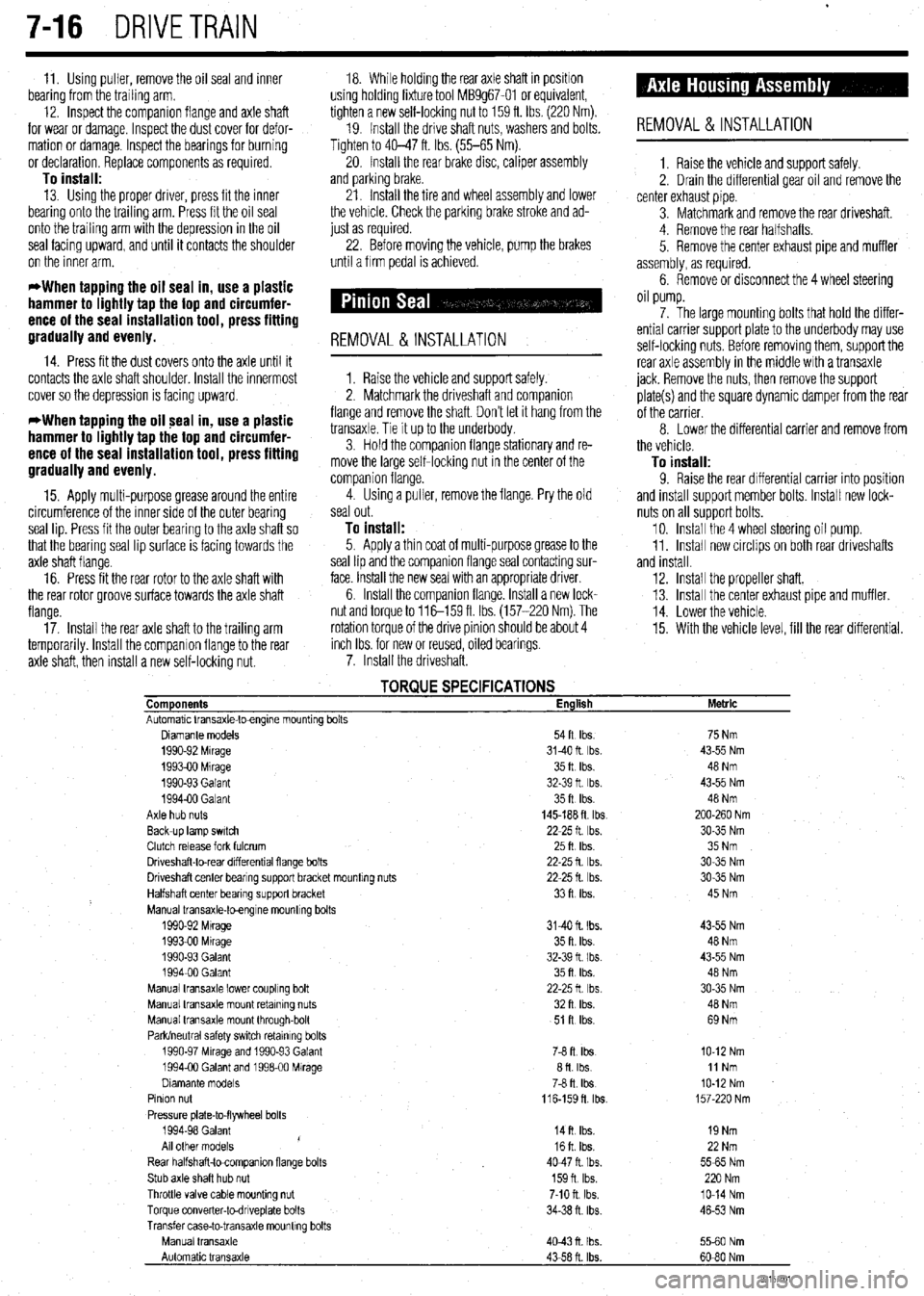
.
7-16 DRIVETRAIN
11. Using puller, remove the oil seal and inner 18. While holding the rear axle shaft in positron
bearing from the trailing arm. using holding fixture tool MB9g67-01 or equivalent,
12. Inspect the companion flange and axle shaft tighten a new self-locking nut to 159 ft. Ibs. (220 Nm).
for wear or damage. Inspect the dust cover for defor- 19. Install the drive shaft nuts, washers and bolts.
mation or damage. Inspect the bearings for burning Tighten to 40-47 ft. Ibs. (55-65 Nm).
or declaration. Replace components as required 20. Install the rear brake disc, caliper assembly
To install: and parking brake.
13. Using the proper driver, press fit the inner
bearing onto the trailing arm. Press fit the oil seal
onto the trailing arm with the depression in the oil
seal facing upward, and until it contacts the shoulder
on the inner arm. 21. Install the tire and wheel assembly and lower
the vehrcle. Check the parking brake stroke and ad-
just as required.
22. Before moving the vehicle, pump the brakes
until a firm pedal is achieved.
*When tapping the oil seal in, use a plastic
hammer to lightly tap the top and circumfer-
ence of the seal installation tool, press fitting
gradually and evenly.
14. Press fit the dust covers onto the axle until it
contacts the axle shaft shoulder. Install the innermost
cover so the deDression is facino
UDWard.
REMOVAL &INSTALLATION
1. Raise the vehicle and support safely.
2. Matchmark the driveshaft and comoanion . ,
*When tapping the oil seal in, use a plastic
hammer to lightly tap the top and circumfer-
ence of the seal installation tool, press fitting
gradually and evenly. flange and remove the shaft. Don’t let it hang from the
transaxle. Tie It up to the underbody.
3. Hold the companion flange stationary and re-
move the large self-locking nut in the center of the
comoanion flanoe.
15. Apply multi-purpose grease around the entire 4: Using a Gller, remove the flange. Pry the old
circumference of the Inner side of the outer bearing seal out.
seal lip. Press fit the outer bearing to the axle shaft so
To install: that the bearrng seal lip surface is facing towards the 5. Apply a thin coat of multi-purpose grease to the
axle shaft flange. seal lip and the companion flange seal contacting sur-
16. Press fit the rear rotor to the axle shaft with face. Install the new seal with an appropriate driver.
the rear rotor groove surface towards the axle shaft 6. Install the companion flange. Install a new lock-
flange. nut and torque to 116-159 fl Ibs. (157-220 Nm). The
17. Install the rear axle shaft to the trailing arm rotation torque of the drive pinion should be about 4
temporarily. Install the companion flange to the rear inch Ibs. for new or reused, oiled bearings
axle shaft, then install a new self-locking nut. 7. Install the driveshaft.
REMOVAL &INSTALLATION
1. Raise the vehicle and support safely.
2. Drain the differential gear oil and remove the
center exhaust pipe.
3. Matchmark and remove the rear driveshaft.
4. Remove the rear halfshafts.
5. Remove the center exhaust pipe and muffler
assembly, as required.
6. Remove or disconnect the 4 wheel steering
oil pump.
7. The large mounting bolts that hold the differ-
ential carrier support plate to the underbody may use
self-locking nuts. Before removing them, support the
rear axle assembly in the middle with a transaxle
jack. Remove the nuts, then remove the support
plate(s) and the square dynamic damper from the rear
of the carrier.
8 Lower the differential carrier and remove from
the vehicle.
To install: 9. Raise the rear differential carrier into position
and install support member bolts. Install new lock-
nuts on all support bolts.
10. Install the 4 wheel steering oil pump.
11. Install new circlips on both rear driveshafts
and install.
12. Install the propeller shaft.
13. Install the center exhaust pipe and muffler.
14. Lower the vehicle.
15. With the vehicle level, fill the rear differential.
TORQUE SPECIFICATIONS Components English
Automatic Vansaxle-toengme mountrng bolts
Diamante models 54ft Ibs.
1990-92 Mrrage 3140ft Ibs.
199390 Mrrage 35ft Ibs.
1990-93 Galant 32-39 ft Ibs.
199400 Galant 35ft Ibs.
Axle hub nuts 145-188 ft tbs
Back-up lamp swatch 22-25 ft Ibs.
Clutch release fork fulcrum 25ft Ibs
Driveshaft-to-rear drfferentral flange bolts 22-25 fl lb?..
Driveshaft center bearrng support bracket mountrng nuts 22-25 fl. Ibs.
Halfshaft center bearing support bracket 33ft Ibs.
Manual transaxle-toengrne mountrng bolts
1990-92 Mtrage 3140 ft. Ibs.
1993-00 Mrrage 35 ft. Ibs.
1990-93 Galant 32-39 fl I bs.
199400 Galant 35ft Ibs.
Manual transaxle lower coupling bolt 22-25ft Ibs
Manual transaxle mount retaining nuts 32ft Ibs.
Manual transaxle mount through-bolt 51 R Ibs.
Park/neutral safety swatch retainrng bolts
1990-97 Mrrage and 1990-93 Galant 76 ft. Ibs
1994-00 Galant and 199600 Mirage afl Ibs
Dramante models
78 fl. Ibs
Pinion nut
116-159fl lb?..
Pressure plate-to-flywheel bolts
1994-98 Galant
14ft Ibs.
/
All other models 16ft Ibs.
Rear halfshaft-tocompanron flange bolts 4047ft Ibs.
Stub axle shaft hub nut 159n Ibs.
Throttle valve cable mounting nut 7-10 ft. Ibs.
Torque converter-todnveplate bolts 34-38 n. ibs
Transfer case-to-transaxle mounttng bolts
Manual transaxle
4043n Ibs.
Automatic transaxle
43-58 ft. Ibs. Metric
75 Nm
43-55 Nm
48 Nm
43-55 Nm
48 Nm
200-260 Nm
30-35 Nm
35 Nm
30-35 Nm
30-35 Nm
45 Nm
43-55 Nm
48 Nm
43-55 Nm
48 Nm
30-35 Nm
40 Nm
69 Nm
IO-12 Nm
11 Nm
IO-12 Nm
157-220 Nm
19 Nm
22 Nm
5565 Nm
220 Nm
lo-14 Nm
46-53 Nm
5560 Nm
60-80 Nm
93157co1
Page 329 of 408
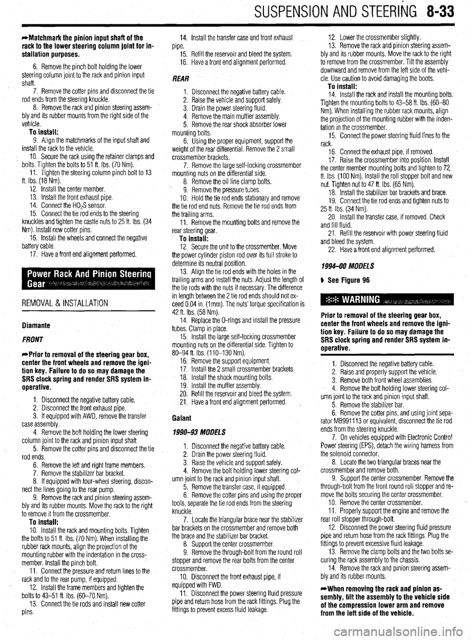
SUSPENSION AND STEERING 8-33
*Matchmark the pinion input shaft of the
rack to the lower steering column joint for in-
stallation purposes.
6. Remove the pinch bolt holding the lower
steering column joint to the rack and pinion input
shaft.
7. Remove the cotter pins and disconnect the tie
rod ends from the steering knuckle.
8. Remove the rack and pinion steering assem-
bly and its rubber mounts from the right side of the
vehicle.
To install: 9. Align the matchmarks of the input shaft and
install the rack to the vehicle.
10. Secure the rack using the retainer clamps and
bolts. Tighten the bolts to 51 ft. Ibs. (70 Nm).
11. Tighten the steering column pinch bolt to 13
ft. Ibs. (18 Nm).
12. Install the center member.
13. Install the front exhaust pipe.
14. Connect the HO$ sensor.
15. Connect the tie rod ends to the steering
knuckles and tighten the castle nuts to 25 ft. Ibs. (34
Nm). Install new cotter pins.
16. Install the wheels and connect the negative
battery cable.
17. Have a front end alignment performed.
REMOVAL &INSTALLATION
Diamante
FRONT
*Prior to removal of the steering gear box,
center the front wheels and remove the igni-
tion key. Failure to do so may damage the
SRS clock spring and render SRS system in-
operative.
1. Disconnect the negative battery cable.
2. Disconnect the front exhaust pipe.
3. If equipped with AWD, remove the transfer
case assembly.
4. Remove the bolt holding the lower steering
column joint to the rack and pinion input shaft.
5. Remove the cotter pins and disconnect the tie
rod ends.
6. Remove the left and right frame members.
7. Remove the stabilizer bar bracket.
8. If equipped with four-wheel steering, discon-
nect the lines going to the rear pump.
9. Remove the rack and pinion steering assem-
bly and its rubber mounts. Move the rack to the right
to remove it from the crossmember.
To install: IO. Install the rack and mounting bolts. Tighten
the bolts to 51 ft. Ibs. (70 Nm). When installing the
rubber rack mounts, align the projection of the
mounting rubber with the indentation in the cross:
member. Install the pinch bolt.
11. Connect the pressure and return lines to the
rack and to the rear pump, if equipped.
12. Install the frame members and tighten the
bolts to 43-51 ft. Ibs. (60-70 Nm).
13. Connect the tie rods and install new cotter
pins. 14. Install the transfer case and front exhaust
pipe.
15. Refill the reservoir and bleed the system.
16. Have a front end alignment performed.
REAR
1. Disconnect the negative battery cable.
2. Raise the vehicle and support safely.
3. Drain the power steering fluid.
4. Remove the main muffler assembly.
5. Remove the rear shock absorber lower
mounting bolts.
6. Using the proper equipment, support the
weight of the rear differential. Remove the 2 small
crossmember brackets.
7. Remove the large self-locking crossmember
mounting nuts on the differential side.
8. Remove the oil line clamp bolts.
9. Remove the pressure tubes.
IO. Hold the tie rod ends stationary and remove
the tie rod end nuts. Remove the tie rod ends from
the trailing arms.
11. Remove the mounting bolts and remove the
rear steering gear.
To install: 12. Secure the unit to the crossmember. Move
the power cylinder piston rod over its full stroke to
determine its neutral position.
13. Align the tie rod ends with the holes in the
trailing arms and install the nuts. Adjust the length of
the tie rods with the nuts if necessary. The difference
in length between the 2 tie rod ends should not ex-
ceed 0.04 in. (1 mm). The nuts’ torque specification is
42 ft. Ibs. (58 Nm).
14. Replace the O-rings and install the pressure
tubes. Clamp in place.
15. Install the large self-locking crossmember
mounting nuts on the differential side. Tighten to
80-94 ft. Ibs. (110-130 Nm).
16. Remove the support equipment.
17. Install the 2 small crossmember brackets.
18. Install the shock mounting bolts.
19. Install the muffler assembly.
20. Refill the reservoir and bleed the system.
21. Have a front end alignment performed. _
Galant
1990-93 MODELS
1. Disconnect the negative battery cable.
2. Drain the power steering fluid.
3. Raise the vehicle and support safely.
4. Remove the bolt holding lower steering col-
umn joint to the rack and pinion input shaft.
5. Remove the transfer case, if equipped.
6. Remove the cotter pins and using the proper
tools, separate the tie rod ends from the steering
knuckle.
7. Locate the triangular brace near the stabilizer
bar brackets on the crossmember and remove both
the brace and the stabilizer bar bracket.
8. Support the center crossmember.
9. Remove the through-bolt from the round roll
stopper and remove the rear bolts from the center
crossmember.
10. Disconnect the front exhaust pipe, if
equipped with FWD.
11. Disconnect the power steering fluid pressure
pipe and return hose from the rack fittings. Plug the
fittings to prevent excess fluid leakage. 12. Lower the crossmember slightly.
13. Remove the rack and pinion steering assem-
bly and its rubber mounts. Move the rack to the right
to remove from the crossmember. Tilt the assembly
downward and remove from the left side of the vehi-
cle. Use caution to avoid damaging the boots.
To install: 14. Install the rack and install the mounting bolts. Tighten the mounting bolts to 43-58 ft. Ibs. (60-80
Nm). When installing the rubber rack mounts, align
the projection of the mounting rubber with the inden-
tation in the crossmember.
15. Connect the power steering fluid lines to the
rack.
16. Connect the exhaust pipe, if removed.
17. Raise the crossmember into position. Install
the center member mounting bolts and tighten to 72
ft. Ibs. (100 Nm). Install the roll stopper bolt and new
nut. Tighten nut to 47 ft. Ibs. (65 Nm).
18. Install the stabilizer bar brackets and brace.
19. Connect the tie rod ends and tighten nuts to
25 ft. Ibs. (34 Nm).
20. Install the transfer case, if removed. Check
and fill fluid.
21. Refill the reservoir with power steering fluid
and bleed the system.
22. Have a front end alignment performed.
1994-M MODELS
+ See Figure 96
Prior to removal of the steering gear box,
center the front wheels and remove the igni-
tion key. Failure to do so may damage the
SRS clock spring and render SRS system in-
operative.
1. Disconnect the negative battery cable.
2. Raise and properly support the vehicle.
3. Remove both front wheel assemblies.
4. Remove the bolt holding lower steering col-
umn joint to the rack and pinion input shaft.
5. Remove the stabilizer bar.
6. Remove the cotter pins, and using joint sepa-
rator MB991 113 or equivalent, disconnect the tie rod
ends from the steering knuckle.
7. On vehicles equipped with Electronic Control
Power steering (EPS), detach the wiring harness from
the solenoid connector.
8. Locate the two triangular braces near the
crossmember and remove both.
9. Support the center crossmember. Remove the
through-bolt from the front round roll stopper and re-
move the bolts securing the center crossmember.
10. Remove the center crossmember. ,
Il. Properly support the engine and remove the
rear roll stopper through-bolt.
12. Disconnect the power steering fluid pressure
pipe and return hose from the rack fittings. Plug the
fittings to prevent excessive fluid leakage.
13. Remove the clamp bolts and the two bolts se-
curing the rack assembly to the chassis.
14. Remove the rack and pinion steering assem-
bly and its rubber mounts.
*When removing the rack and pinion as-
sembly, tilt the assembly to the vehicle side
of the compression lower arm and remove
from the left side of the vehicle.
Page 331 of 408
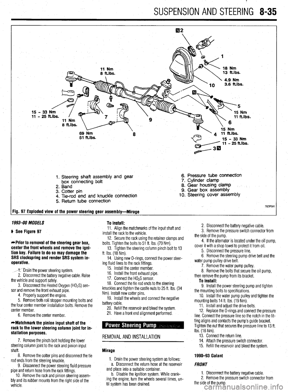
SUSPENSION AND STEERING 8-35
1. Steering shaft assembly and gear
box connecting bolt
2. Band
3. Cotter pin
4. Tie-rod end and knuckle connection
5. Return tube connection 6. Pressure tube connection
7. Cylinder clamp
8. Gear housing clamp
9. Gear box assembly 10. Steering cover assembly
7923PGAl FiD= 97 Exploded view of the power steering gear assembly-Mirage
1993-90 MODELS To install:
) See Figure 97
*Prior to removal of the steering gear box,
center the front wheels and remove the igni-
tion key. Failure to do so may damage the
SRS clockspring and render SRS system in-
operative.
,mr;iin thepower steering system.
2. Disconnect the battery negative cable. Raise
the vehicle and support safely.
3. Disconnect the Heated Oxygen (HOPS) sen-
sor and remove the front exhaust pipe.
4. Properly support the engine.
5. Remove both roll stopper mounting bolts and
the four center member installation bolts. Remove the
center member.
6. Remove the center member. 11. Align the matchmarks of the input shaft and
install the rack to the vehicle.
12. Secure the rack using the retainer clamps and
bolts. Tighten the bolts to 51 ft. Ibs. (70 Nm).
13. Tighten the steering column pinch bolt to 13
ft. Ibs. (18 Nm).
14. Using new O-rings, connect the power steer-
ing fluid lines to the rack fittings.
15. Install the center member.
16. Install the front exhaust pipe.
17. Connect the H02S sensor.
18. Connect the tie rod ends to the steering
knuckles and tighten the castle nuts to 25 ft. Ibs. (34
Nm). Install new cotter pins.
19. Install the wheels and connect the negative
battery cable.
20. Refill ‘the reservoir and bleed the system.
21. Have a front end alignment performed.
stallation purposes. -
7. Remove the pinch bolt holding the lower REMOVALANDINSTALLATION
steering column joint to the rack and pinion input
shaft.
8. Remove the cotter pins and disconnect the tie
rod ends from the steering knuckle.
9. Disconnect the power steering fluid pressure
pipe and return hose from the rack fittings.
IO. Remove the rack and pinion steering assem-
bly and its rubber mounts from the right side of the
vehicle. Mirage
1, Drain the power steering system as follows:
a. Disconnect the return hose at the reservoir
and place into a suitable container.
b. Disable the ignition system. While crank-
ing the engine, turn the wheels several times, un-
til system has been drained. 2. Disconnect the battery negative cable.
3. Remove the pressure switch connector from
the side of the pump.
4. If the alternator is located under the oil pump,
cover it with a shop towel to protect it from oil.
5. Disconnect the pressure line.
6. Remove the steering pump drive belt and the
water pump pulley drive belt.
7. Remove the water pump pulley.
8. Remove the bolts that secure the oil pump,
then remove the pump from its bracket.
To install: 9. Install the power steering pump and tighten
the mounting bolts to specifications.
IO. Install the water pump pulley and tighten the
mounting bolts 14 ft. Ibs. (19 Nm).
11. Install and adjust the drive belts.
12. Replace the O-rings and connect the pressure
line. Connect the pressure line so the notch in the fit-
ting aligns and contacts the pump’s guide bracket.
Tighten the nut that secures the pressure line to 13 ft.
Ibs. (18 Nm).
13. Connect the return line.
14. Attach the pressure switch connector.
15. Refill the reservoir and bleed the system.
1990-93 Galant
FRONT
1. Disconnect the battery negative cable.
2. Remove the pressure switch connector from
the side of the pump.
Page 332 of 408
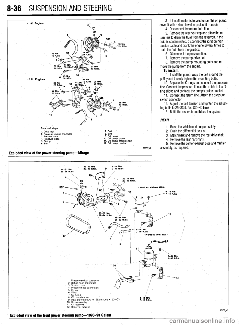
8-36 SUSPENSION AND STEERING
4 SL Engine>
<1.8L Engine>
Removal steps
1. Drive belt
7. BoIt
2. Pressure switch connector
8. Bolt
3. Suction hose
9. Oil pump
4. Pressure hose
10. Oil pump brace
2 Elrg
11. Oil pumo bracket stay
12. Oil pump bracket
93158gal
Exploded view of the power steering pump-Mirage
3. If the alternator is located under the oil pump,
cover it with a shop towel to protect it from oil.
4. Disconnect the return fluid line.
5. Remove the reservoir cap and allow the re-
turn line to drain the fluid from the reservoir. If the
fluid is contaminated, disconnect the ignition high
tension cable and crank the engine several times to
drain the fluid from the gearbox.
6. Disconnect the pressure line.
7. Remove the pump drive belt.
8. Remove the pump mounting bolts and re-
move the pump from the engine.
To install: 9. Install the pump, wrap the belt around the
pulley and loosely tighten the mounting bolts.
10. Replace the O-rings and connect the pressure
line. Connect the pressure line so the notch in the fit-
ting aligns and contacts the pump’s guide bracket.
1 I. Connect the return line. Attach the pressure
switch connector.
12. Adjust the belt tension and tighten the adjust-
ing bolts to 25-33 ft. Ibs. (35-45 Nm).
13. Refill the reservoir and bleed the system.
REAR
1. Raise the vehicle and support safely.
2. Drain the differential gear oil.
3. Matchmark and remove the rear driveshaft.
4. Remove the rear halfshafts.
5. Remove the center exhaust pipe and muffler
assembly, as required.
35-45 Nm 9-14 Nm
14-Z Nm 25-33 ft.lbs.
9 7-10 klbs.
2 g-lb Nm
7-10 ft.lbs.