1900 MITSUBISHI DIAMANTE oil pressure
[x] Cancel search: oil pressurePage 396 of 408
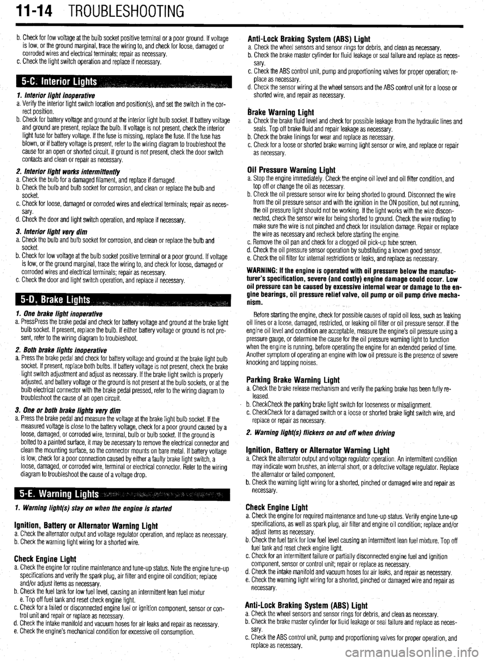
II-14 TROUBLESHOOTING
b. Check for low voltage at the bulb socket positive terminal or a poor ground. If voltage
is low, or the ground marginal, trace the wiring to, and check for loose, damaged or
corroded wires and electrical terminals; repair as necessary.
c. Check the light switch operation and replace if necessary.
1. Interior light inoperative
a. Verify the interior light switch location and position(s), and set the switch in the cor-
rect position.
b. Check for battery voltage and ground at the interior light bulb socket. If battery voltage
and ground are present, replace the bulb. If voltage is not present, check the interior
light fuse for battery voltage. If the fuse is missing, replace the fuse. If the fuse has
blown, or if battery voltage is present, refer to the wiring diagram to troubleshoot the
cause for an open or shorted circuit. If ground is not present, check the door switch
contacts and clean or repair as necessary.
2. Interior light works intermittent/y
a. Check the bulb for a damaged filament, and replace if damaged.
b. Check the bulb and bulb socket for corrosion, and clean or replace the bulb and
socket.
c. Check for loose, damaged or corroded wires and electrical terminals; repair as neces-
sary.
d. Check the door and light switch operation, and replace if necessary.
3. Interior light very dim
a. Check the bulb and bulb socket for corrosion, and clean or replace the bulb and
socket.
b. Check for low voltage at the bulb socket positive terminal or a poor ground. If voltage
is low, or the ground marginal, trace the wiring to, and check for loose, damaged or
corroded wires and electrical terminals; repair as necessary.
c. Check the door and light switch operation, and replace if necessary.
1. One brake light inoperative
a. PressPress the brake pedal and check for battery voltage and ground at the brake light
bulb socket. If present, replace the bulb. If either battery voltage or ground is not pre-
sent, refer to the wiring diagram to troubleshoot.
2. Both brake lights inoperative
a. Press the brake pedal and check for battery voltage and grou’nd at the brake light bulb
socket. If present, replace both bulbs. If battery voltage is not present, check the brake
light switch adjustment and adjust as necessary. If the brake light switch is properly
adjusted, and battery voltage or the ground is not present at the bulb sockets, or at the
bulb electrical connector with the brake pedal pressed, refer to the wiring diagram to
troubleshoot the cause of an open circuit.
3. One or both brake lights very dim
a. Press the brake pedal and measure the voltage at the brake light bulb socket. If the
measured voltage is close to the battery voltage, check for a poor ground caused by a
loose, damaged, or corroded wire, terminal, bulb or bulb socket. If the ground is
bolted to a painted surface, it may be necessary to remove the electrical connector and
clean the mounting surface, so the connector mounts on bare metal. If battery voltage
is low, check for a poor connection caused by either a faulty brake light switch, a
loose, damaged, or corroded wire, terminal or electrical connector. Refer to the wiring
diagram to troubleshoot the cause of a voltage drop.
1. Warning light(s) stay on when the engine is started
Ignition, Battery or Alternator Warning light a. Check the alternator output and voltage regulator operation, and replace as necessary.
b. Check the warning light wiring for a shorted wire.
Check Engine Light a. Check the engine for routine maintenance and tune-up status. Note the engine tune-up
specifications and verify the spark plug, air filter and engine oil condition; replace
and/or adjust items as necessary.
b. Check the fuel tank for low fuel level, causing an intermittent lean fuel mixtur
e. Top off fuel tank and reset check engine light.
c. Check for a failed or disconnected engine fuel or ignition component, sensor or con-
trol unit and repair or replace as necessary.
d. Check the intake manifold and vacuum hoses for air leaks and repair as
necessary.
e. Check the engine’s mechanical condition for excessive oil consumption.
Anti-Lock Braking System (ABS) Light a. Check the wheel sensors and sensor rings for debris, and clean as necessary.
b. Check the brake master cylinder for fluid leakage or seal failure and replace as neces-
sary.
c, Check the ABS control unit, pump and proportioning valves for proper operation; re-
place as necessary.
d. Check the sensor wiring at the wheel sensors and the ABS control unit for a loose or
shorted wire, and repair as necessary.
brake Warning Light a. Check the brake fluid level and check for possible leakage from the hydraulic lines and
seals. Top off brake fluid and repair leakage as necessary.
b. Check the brake linings for wear and replace as necessary.
c. Check for a loose or shot-ted brake warning light sensor or wire, and replace or repair
as necessary.
Oil Pressure Warning Light a. Stop the engine immediately. Check the engine oil level and oil filter condition, and
top off or change the oil as necessary.
b. Check the oil pressure sensor wire for being shorted to ground. Disconnect the wire
from the oil pressure sensor and with the ignition in the ON position, but not running,
the oil pressure light should not be working. If the light works with the wire discon-
nected, check the sensor wire for being shorted to ground. Check the wire routing to
make sure the wire is not pinched and check for insulation damage. Repair or replace
the wire as necessary and recheck before starting the engine.
c. Remove the oil pan and check for a clogged oil pick-up tube screen.
d. Check the oil pressure sensor operation by substituting a known good sensor.
e. Check the oil filter for internal restrictions or leaks, and replace as necessary.
WARNING: If the engine is operated with oil pressure below the manufac-
turer’s specification, severe (and costly) engine damage could occur. Low
oil pressure can be caused by excessive internal wear or damage to the en-
gine bearings, oil pressure relief valve, oil pump or oil pump drive mecha-
nism.
Before starting the engine, check for possible causes of rapid oil loss, such as leaking
oil lines or a loose, damaged, restricted, or leaking oil filter or oil pressure sensor. If the
engine oil level and condition are acceptable, measure the engine’s oil pressure using a
pressure gauge, or determine the cause for the oil pressure warning light to function
when the engine is running, before operating the engine for an extended period of time.
Another symptom of operating an engine with low oil pressure is the presence of severe
knocking and tapping noises.
Parking Brake Warning Light a. Check the brake release mechanism and verify the parking brake has been fully re-
leased.
b. CheckCheck the parking brake light switch for looseness or misalignment.
c. CheckCheck for a damaged switch or a loose or shorted brake light switch wire, and
replace or repair as necessary.
2. Warning light(s) flickers on and off when driving
Ignition, Battery or Alternator Warning Light a. Check the alternator output and voltage regulator operation. An intermittent condition
may indicate worn brushes, an internal short, or a defective voltage regulator. Replace
the alternator or failed component.
b. Check the warning light wiring for a shorted, pinched or damaged wire and repair as
necessary.
Check Engine Light a. Check the engine for required maintenance and tune-up status. Verify engine tune-up
specifications, as well as spark plug, air filter and engine oil condition; replace and/or
adjust items as necessary.
b. Check the fuel tank for low fuel level causing an intermittent lean fuel mixture. Top off
fuel tank and reset check engine light.
c. Check for an intermittent failure or partially disconnected engine fuel and ignition
component, sensor or control unit; repair or replace as necessary.
d. Check the intake manifold and vacuum hoses for air leaks, and repair as necessary.
e. Check the warning light wiring for a shorted, pinched or damaged wire and repair as
necessary.
Anti-Lock Braking System (ABS) Light a. Check the wheel sensors and sensor rings for debris, and clean as necessary.
b. Check the brake master cylinder for fluid leakage or seal failure and replace as neces-
sary.
c. Check the ABS control unit, pump and proportioning valves for proper operation, and
replace as necessary.
Page 397 of 408
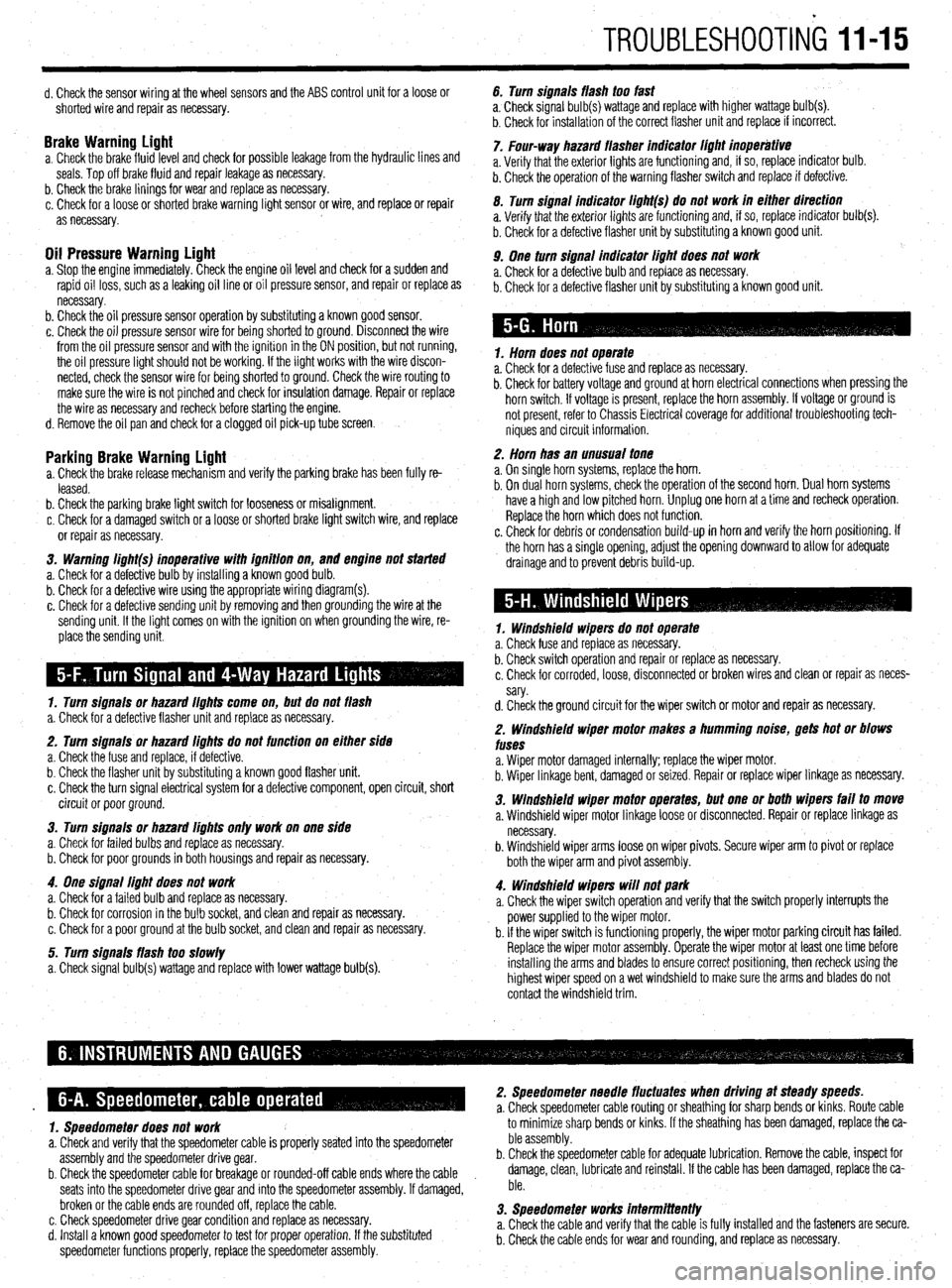
TROUBLESHOOTING 1145
d. Check the sensor wiring at the wheel sensors and the ABS control unit for a loose or
shorted wire and repair as necessary.
Brake Warninu Liaht a. Check the brakefluid~evel and check for possible leakage from the hydraulic lines and
seals. Top off brake fluid and repair leakage as necessary.
b. Check the brake linings for wear and replace as necessary.
c. Check for a loose or shorted brake warning light sensor or wire, and replace or repair
as necessary.
Oil Pressure Warning Light a. Stop the engine immediately. Check the engine oil level and check for a sudden and
rapid oil loss, such as a leaking oil line or oil pressure sensor, and repair or replace as
necessary.
b. Check the oil pressure sensor operation by substituting a known good sensor.
c. Check the oil pressure sensor wire for being shorted to ground. Disconnect the wire
from the oil pressure sensor and with the ignition in the ON position, but not running,
the oil pressure light should not be working. If the light works with the wire discon-
nected, check the sensor wire for being shorted to ground. Check the wire routing to
make sure the wire is not pinched and check for insulation damage. Repair or replace
the wire as necessary and recheck before starting the engine.
d. Remove the oil pan and check for a clogged oil pick-up tube screen.
Parking Brake Warning Light a. Check the brake release mechanism and verify the parking brake has been fully re-
leased.
b. Check the parking brake light switch for looseness or misalignment.
c. Check for a damaged switch or a loose or shorted brake light switch wire, and replace
or repair as necessary.
3. Warning li#ht(s) inoperative with iflnition on,
and engine not started
a. Check for a defective bulb by installing a known good bulb.
b. Check for a defective wire using the appropriate wiring diagram(s).
c. Check for a defective sending unit by removing and then grounding the wire at the
sending unit. If the light comes on with the ignition on when grounding the wire, re-
place the sending unit.
1. Turn siflnais or hazard iiflhts come on, but do not flash
a. Check for a defective flasher unit and replace as necessary.
2. Turn signals or hazard iiflhts do not function on either side
a. Check the fuse and replace, if defective.
b. Check the flasher unit by substituting a known good flasher unit.
c. Check the turn signal electrical system for a defective component, open circuit, short
circuit or poor ground.
3. Turn siflnais or hazard lights only work on one side
a. Check for failed bulbs and replace as necessary.
b. Check for poor grounds in both housings and repair as necessary.
4. One siflnai light does not work
a. Check for a failed bulb and replace as necessary.
b. Check for corrosion in the bulb socket, and clean and repair as necessary.
c. Check for a poor ground at the bulb socket, and clean and repair as necessary.
5. Turn signals flash too slowly
a. Check signal bulb(s) wattage and replace with lower wattage bulb(s). 6. Turn signals flash too fast
a, Check signal bulb(s) wattage and replace with higher wattage bulb(s).
b. Check for installation of the correct flasher unit and replace if incorrect.
7. Four-way hazard flasher indicator iiflhi inoperative
a. Verify that the exterior lights are functioning and, if so, replace indicator bulb.
b. Check the operation of the warning flasher switch and replace if defective.
0. Turn signal indicator ii#ht(s) do not work in either direction
a. Verify that the exterior lights are functioning and, if so, replace indicator bulb(s).
b. Check for a defective flasher unit by substituting a known good unit.
9. One turn signal indicator liflht does not work
a. Check for a defective bulb and replace as necessary.
b. Check for a defective flasher unit by substituting a known good unit.
1. Horn does not operate
a. Check for a defective fuse and replace as necessary.
b. Check for battery voltage and ground at horn electrical connections when pressing the
horn switch. If voltage is present, replace the horn assembly. If voltage or ground is
not present, refer to Chassis Electrical coverage for additional troubleshooting tech-
niques and circuit information.
2. Horn has an unusual tone
a. On single horn systems, replace the horn.
b. On dual horn systems, check the operation of the second horn. Dual horn systems
have a high and low pitched horn. Unplug one horn at a time and recheck operation.
Replace the horn which does not function.
c. Check for debris or condensation build-up in horn and verify the horn positioning. If
the horn has a single opening, adjust the opening downward to allow for adequate
drainage and to prevent debris build-up.
1. Windshield wipers do not operate
a. Check fuse and replace as necessary.
b. Check switch operation and repair or replace as necessary.
c. Check for corroded, loose, disconnected or broken wires and clean or repair as neces-
sary.
d. Check the ground circuit for the wiper switch or motor and repair as necessary.
2. Windshield wiper motor makes a humming noise, gets hot or blows
fuses
a. Wiper motor damaged internally; replace the wiper motor.
b. Wiper linkage bent, damaged or seized. Repair or replace wiper linkage as necessary.
3. Windshield wiper motor operates, but one or both wipers fail to move
a. Windshield wiper motor linkage loose or disconnected. Repair or replace linkage as
necessary.
b. Windshield wiper arms loose on wiper pivots. Secure wiper arm to pivot or replace
both the wiper arm and pivot assembly.
4. Windshield wipers will not park
a. Check the wiper switch operation and verify that the switch properly interrupts the
power supplied to the wiper motor.
b. If the wiper switch is functioning properly, the wiper motor parking circuit has failed.
Replace the wiper motor assembly. Operate the wiper motor at least one time before
installing the arms and blades to ensure correct positioning, then recheck using the
highest wiper speed on a wet windshield to make sure the arms and blades do not
contact the windshield trim.
1. Speedometer does not work to minimize sharp bends or kinks.
If the sheathing has been
damaged, replace the ca-
a. Check and verify that the speedometer cable is properly seated into the speedometer ble assembly.
assembly and the speedometer drive gear. b. Check the speedometer cable for adequate lubrication. Remove the cable, inspect for
b. Check the speedometer cable for breakage or rounded-off cable ends where the cable damage, clean, lubricate and reinstall. If the cable has been damaged, replace the ca-
seats into the speedometer drive gear and into the speedometer assembly. If damaged, ble.
broken or the cable ends are rounded off, replace the cable.
c. Check speedometer drive gear condition and replace as necessary. 3. Speedometer works intermittently
d. Install a known good speedometer to test for proper operation. If the substituted a. Check the cable and verify that the cable is fully installed and the fasteners are secure.
speedometer functions properly, replace the speedometer assembly. b. Check the cable ends for wear and rounding, and replace as necessary.
Page 399 of 408
GLOSSARY 11-17
AIR/FUEL RATIO: The ratio of air-to-gasoline by weight in the fuel mixture
drawn into the engine.
AIR INJECTION: One method of reducing harmful exhaust emissions by in-
jecting air into each of the exhaust ports of an engine. The fresh air entering
the hot exhaust manifold causes any remaining fuel to be burned before it can
exit the tailpipe.
ALTERNATOR: A device which produces AC (alternating current) which is
converted to DC (direct current) to charge the car battery.
AMMETER: An instrument, calibrated in amperes, used to measure the flow
of an electrical current in a circuit. Ammeters are always connected in series
with the circuit being tested.
AMPERE: The rate of flow of electrical current present when one volt of elec-
trical pressure is applied against one ohm of electrical resistance.
ANALOG COMPUTER: Any microprocessor that uses similar (analogous)
electrical signals to make its calculations.
ARMATURE: A laminated, soft iron core wrapped by a wire that converts elec-
trical energy to mechanical energy as in a motor or relay. When rotated in
a magnetic field, it changes mechanical energy into electrical energy as in a
generator.
ATMOSPHERIC PRESSURE: The pressure on the Earth’s surface caused
by the weight of the air in the atmosphere. At sea level, this pressure is 14.7
psi at 32°F (101 kPa at OOC).
ATOMIZATION: The breaking down of a liquid into a fine mist that can be
suspended in air.
AXIAL PLAY: Movement parallel to a shaft or bearing bore.
BACKFIRE: The sudden combustion of gases in the intake or exhaust sys-
tem that results in a loud explosion.
BACKLASH: The clearance or play between two parts, such as meshed gears.
BACKPRESSURE: Restrictions in the exhaust system that slow the exit of
exhaust gases from the combustion chamber.
BAKELITE[reg]: A heat resistant, plastic insulator material commonly used
in printed circuit boards and transistorized components.
BALL BEARING: A bearingmade up of hardened inner and outer races be-
tween which hardened steel’balls roll.
BALLAST RESISTOR: A resistor in the primary ignition circuit that lowers
voltage after the engine is started to reduce wear on ignition components.
BEARING: A friction reducing, supportive device usually located between a
stationary part and a moving part.
BI-METAL TEMPERATURE SENSOR: Anv sensor or switch made of two
dissimilar types of metal that bend when heated or cooled due to the different
expansion rates of the alloys. These types of sensors usually function as an
on/off switch. BLOW-BY: Combustion gases, composed of water vapor and unburned fuel,
that leak past the piston rings into the crankcase during normal engine oper-
ation. These gases are removed by the PCV system to prevent the buildup of
harmful acids in the crankcase.
BRAKE PAD: A brake shoe and lining assembly used with disc brakes.
BRAKE SHOE: The backing for the brake lining. The term is, however, usu-
ally applied to the assembly of the brake backing and lining.
BUSHING: A liner, usually removable, for a bearing; an anti-friction liner used
in place of a bearing.
CALIPER: A hydraulically activated device in a disc brake system, which is
mounted straddling the brake rotor (disc). The caliper contains at least one
piston and two brake pads. Hydraulic pressure on the piston(s) forces the pads
against the rotor.
CAMSHAFT: A shaft in the engine on which are the lobes (cams) which op-
erate the valves. The camshaft is driven by the crankshaft, via a belt, chain or
gears, at one half the crankshaft speed.
CAPACITOR: A device which stores an electrical charge.
CARBON MONOXIDE (CO): A colorless, odorless gas given off as a nor-
mal byproduct of combustion. It is poisonous and extremely dangerous in con-
fined areas, building up slowly to toxic levels without warning if adequate ven-
tilation is not available.
CARBURETOR: A device, usually mounted on the intake manifold of an en-
gine, which mixes the air and fuel in the proper proportion to allow even com-
bustion
CATALYTIC CONVERTER: A device installed in the exhaust system, like a
muffler, that converts harmful byproducts of combustion into carbon dioxide
and water vapor by means of a heat-producing chemical reaction.
CENTRIFUGAL ADVANCE: A mechanical method of advancing the spark
timing by using flyweights in the distributor that react to centrifugal force gen-
erated by the distributor shaft rotation.
CHECK VALVE: Any one-way valve installed to permit the flow of air, fuel or
vacuum in one direction only.
CHOKE: The valve/plate that restricts the amount of air entering an engine on
the induction stroke, thereby enriching the air:fuel ratio.
CIRCUIT: Any unbroken path through which an electrical current can flow.
Also used to describe fuel flow in some instances.
CIRCUIT BREAKER: A switch which protects an electrical circuit from
overload by opening the circuit when the current flow exceeds a pre-
determined level. Some circuit breakers must be reset manually, while most
reset automatically.
COIL (IGNITION): Part of the ignition system that boosts the relatively low
voltage supplied by the car’s electrical system to the high voltage required to
fire the spark plugs.
Page 401 of 408
GLOSSARY 1149
GENERATOR: A device which produces direct current (DC) necessary to
charge the battery. OVERHEAD CAMSHAFT (OHC): An engine configuration in which the
camshaft is mounted on top of the cylinder head and operates the valve either
directly or by means of rocker arms.
HEAT RANGE: A term used to describe the ability of a spark plug to carry
away heat. Plugs with longer nosed insulators take longer to carry heat off
effectively.
HUB: The center part of a wheel or gear.
HYDROCARBON (HC): Any chemical compound made up of hydrogen
and carbon. A major pollutant formed by the engine as a by-product of
combustion.
HYDROMETER: An instrument used to measure the specific gravity of a so-
lution.
INCH POUND (inch Ibs.; sometimes in. lb. or in. Ibs.): One twelfth
.
of a foot pound.
INDUCTION: A means of transferring electrical energy in the form of a mag-
netic field. Principle used in the ignition coil to increase voltage.
INJECTOR: A device which receives metered fuel under relatively low pres-
sure and is activated to inject the fuel into the engine under relatively high
pressure at a predetermined time.
INPUT SHAFT: The shaft to which torque is applied, usually carrying the dri-
ving gear or gears.
INTAKE MANIFOLD: A casting of passages or pipes used to conduct air or
a fuel/air mixture to the cylinders.
JOURNAL: The bearing surface within which a shaft operates.
KEY: A small block usually fitted in a notch between a shaft and a hub to pre-
vent slippage of the two parts.
MANIFOLD: A casting of passages or set of pipes which connect the cylin-
ders to an inlet or outlet source.
MASTER CYLINDER: The primary fluid pressurizing device in a hydraulic
system. In automotive use, it is found in brake and hydraulic clutch systems
and is pedal activated, either directly or, in a power brake system, through the
power booster.
MODULE: Electronic control unit, amplifier or igniter of solid state or inte-
grated design which controls the current flow in the ignition primary circuit
based on input from the pick-up coil. When the module opens the primary cir-
cuit, high secondary voltage is induced in the coil.
NEEDLE BEARING: A bearing which consists of a number (usually a large
number) of long, thin rollers.
OHM: The unit used to measure the resistance of conductor-to-electrical flow.
One ohm is the amount of resistance that limits current flow to one ampere in
a circuit with one volt of pressure.
OHMMETER: An instrument used for measuring the resistance, in ohms, in
an electrical circuit.
OUTPUT SHAFT: The shaft which transmits torque from a device, such as a
transmission. OVERHEAD VALVE (OHV): An engine configuration in which all of the
valves are located in the cylinder head
and the camshaft is located in the cylin-
der block. The camshaft operates the valves via lifters and pushrods.
OXIDES OF NITROGEN (NOx): Chemical compounds of nitrogen produced
as a byproduct of combustion. They combine with hydrocarbons to produce
smog.
OXYGEN SENSOR: Used with a feedback system to sense the presence of
oxygen in the exhaust gas and signal the computer which can use the voltage
signal to determine engine operating efficiency and adjust the air/fuel ratio.
PINION: The smaller of two gears. The rear axle pinion drives the ring gear
which transmits motion to the axle shafts.
PISTON RING: An open-ended ring which fits into a groove on the outer di-
ameter of the piston. Its chief function is to form a seal between the piston and
cylinder wall. Most automotive pistons have three rings: two for compression
sealing; one for oil sealing.
PRELOAD: A predetermined load placed on a bearing during assembly or by
adjustment.
PRESS FIT: The mating of two parts under pressure, due to the inner diam-
eter of one being smaller than the outer diameter of the other, or vice versa;
an interference fit.
PRIMARY CIRCUIT: The low voltage side of the ignition system which con-
sists of the ignition switch, ballast resistor or resistance wire, bypass, coil,
electronic control unit and pick-up coil as well as the connecting wires and
harnesses.
RACE: The surface on the inner or otiter ring of a bearing on which the balls,
needles or rollers move.
REGULATOR: A device which maintains the amperage and/or voltage levels
of a circuit at predetermined values.
RELAY: A switch which automatically opens and/or closes a circuit.
RESISTANCE: The opposition to the flow of current through a circuit or elec-
trical device, and is measured in ohms. Resistance is equal to the voltage di-
vided by the amperage.
RESISTOR: A device, usually made of wire, which offers a preset amount of
resistance in an electrical circuit.
RING GEAR: The name given to a ring-shaped gear attached to a differential
case, or affixed to a flywheel or as part of a planetary gear set.
ROLLER BEARING: A bearing made up of hardened inner and outer races
between which hardened steel rollers move.
ROTOR: (1.) The disc-shaped part of a disc brake assembly, upon which the
brake pads bear; also called, brake disc. (2.) The device mounted atop the dis-
tributor shaft, which passes current to the distributor cap tower contacts.
Page 402 of 408
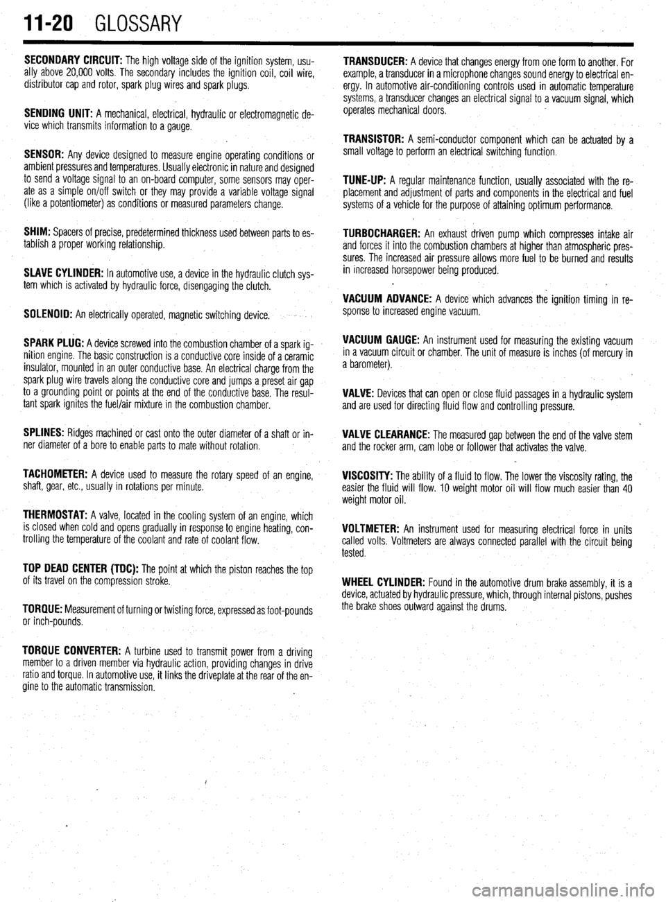
II-20 GLOSSARY
SECONDARY CIRCUIT: The high voltage side of the ignition system, usu-
ally above 20,000 volts. The secondary includes the ignition coil, coil wire,
distributor cap and rotor, spark plug wires and spark plugs.
SENDING UNIT: A mechanical, electrical, hydraulic or electromagnetic de-
vice which transmits information to a gauge.
SENSOR: Any device designed to measure engine operating conditions or
ambient pressures and temperatures. Usually electronic in nature and designed
to send a voltage signal to an on-board computer, some sensors may oper-
ate as a simple on/off switch or they may provide a variable voltage signal
(like a potentiometer) as conditions or measured parameters change.
SHIM: Spacers of precise, predetermined thickness used between parts to es-
tablish a proper working relationship.
SLAVE CYLINDER: In automotive use, a device in the hydraulic clutch sys-
tem which is activated by hydraulic force, disengaging the clutch.
SOLENOID: An electrically operated, magnetic switching device.
SPARK PLUG: A device screwed into the combustion chamber of a spark ig-
nition engine. The basic construction is a conductive core inside of a ceramic
insulator, mounted in an outer conductive base. An electrical charge from the
spark plug wire travels along the conductive core and jumps a preset air gap
to a grounding point or points at the end of the conductive base. The resul-
tant spark ignites the fuel/air mixture in the combustion chamber.
SPLINES: Ridges machined or cast onto the outer diameter of a shaft or in-
ner diameter of a bore to enable parts to mate without rotation.
TACHOMETER: A device used to measure the rotary speed of an engine,
shaft, gear, etc., usually in rotations per minute.
THERMOSTAT: A valve, located in the cooling system of an engine, which
is closed when cold and opens gradually in response to engine heating, con-
trolling the temperature of the coolant and rate of coolant flow.
TOP DEAD CENTER (TDC): The point at which the piston reaches the top
of its travel on the compression stroke.
TORQUE: Measurement of turning or twisting force, expressed as foot-pounds
or inch-pounds.
TORQUE CONVERTER: A turbine used to transmit power from a driving
member to a driven member via hydraulic action, providing changes in drive
ratio and torque. In automotive use, it links the driveplate at the rear of the en-
gine to the automatic transmission. TRANSDUCER: A device that changes energy from one form to another. For
example, a transducer in a microphone changes sound energy to electrical en-
ergy. In automotive air-conditioning controls used in automatic temperature
systems, a transducer changes an electrical signal to a vacuum signal, which
operates mechanical doors.
TRANSISTOR: A semi-conductor component which can be actuated by a
small voltage to perform an electrical switching function.
TUNE-UP: A regular maintenance function, usually associated with the re-
placement and adjustment of parts and components in the electrical and fuel
systems of a vehicle for the purpose of attaining optimum performance.
TURBOCHARGER: An exhaust driven pump which compresses intake air
and forces it into the combustion chambers at higher than atmospheric pres-
sures The increased air pressure allows more fuel to be burned and results
in increased horsepower being produced.
.
VACUUM ADVANCE: A device which advances the ignition timing in re-
sponse to increased engine vacuum.
VACUUM GAUGE: An instrument used for measuring the existing vacuum
in a vacuum circuit or chamber. The unit of measure is inches (of mercury in
a barometer).
VALVE: Devices that can open or close fluid passages in a hydraulic system
and are used for directing fluid flow and controlling pressure.
VALVE CLEARANCE: The measured gap between the end of the valve stem
and the rocker arm, cam lobe or follower that activates the valve.
VISCOSITY: The ability of a fluid to flow. The lower the viscosity rating, the
easier the fluid will flow. 10 weight motor oil will flow much easier than 40
weight motor oil.
VOLTMETER: An instrument used for measuring electrical force in units
called volts. Voltmeters are always connected parallel with the circuit being
tested.
WHEEL CYLINDER: Found in the automotive drum brake assembly, it is a
device, actuated by hydraulic pressure, which, through internal pistons, pushes
the brake shoes outward against the drums.
Page 404 of 408
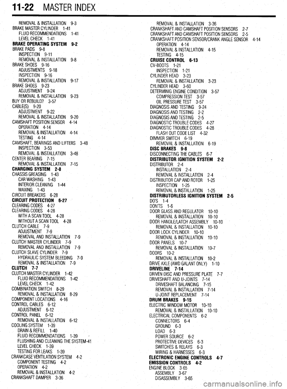
11-22 MASTER INDEX
REMOVAL&INSTALLATION 9-3
BRAKE MASTERCYLINDER I-41
FLUIDRECOMMENDATIONS 1-41
LEVELCHECK I-41
BRAKE OPERATING SYSTEM B-2
BRAKEPADS 9-8
INSPECTION 9-11
REMOVAL & INSTALLATION 9-8
'
BRAKESHOES 9-16
ADJUSTMENTS 9-18
INSPECTION 9-16
REMOVAL&INSTALLATION 9-17
BRAKESHOES 9-23
ADJUSTMENT 9-24
REMOVAL & INSTALLATION 9-23
BUY OR REBUILD? 3-57
CABLE(S) 9-20
ADJUSTMENT 9-22
REMOVAL & INSTALLATION 9-20
CAMSHAFT POSITIONSENSOR 4-14
OPERATION 4-14
REMOVAL &INSTALLATION 4-14
TESTING 4-14
CAMSHAFT, BEARINGSAND LIFTERS 3-48
INSPECTION 3-53
REMOVAL & INSTALLATION 3-48
CENTERBEARING 7-15
REMOVAL & INSTALLATION 7-15
CHARGING SYSTEM 2-8
CHASSISGREASING l-43
CAR WASHING 1-43
INTERIOR CLEANING l-44
WAXING l-43
CIRCUIT BREAKERS 6-28
CIRCUIT PROTECTION 6-27
CLEARING CODES 4-27
CLEARING CODES 4-28
WITHASCANTOOL 4-28
WITHOUTASCANTOOL 4-28
CLUTCH CABLE 7-9
ADJUSTMENT 7-9
REMOVAL AND INSTALLATION 7-9
CLUTCH MASTER CYLINDER 7-9
REMOVALANDINSTALLATION 7-9
CLUTCHSLAVECYLINDER 7-9
HYDRAULIC SYSTEM BLEEDING 7-9
REMOVAL &INSTALLATION 7-9
CLUTCH 7-7
CLUTCHMASTERCYLINDER l-42
FLUIDRECOMMENDATIONS l-42
LEVELCHECK l-42
COMBINATION SWITCH 8-29
REMOVAL &INSTALLATION 8-29
COMPONENTLOCATIONS 4-16
CONTROL CABLES 6-12
ADJUSTMENT 6-12
CONTROL PANEL 6-12
REMOVAL&INSTALLATION 6-12
COOLINGSYSTEM l-39
DRAIN &REFILL I-40
FLUIDRECOMMENDATIONS l-39
FLUSHINGANDCLEANING THESYST
EM-41
LEVELCHECK l-39
TESTING FOR LEAKS l-39
CRANKCASEVENTILATIONSYSTEM 4-2
COMPONENTTESTING 4-2
OPERATION 4-2
REMOVAL &INSTALLATION 4-2
CRANKSHAFTDAMPER 3-36 REMOVAL &INSTALLATION 3-36
CRANKSHAFTANDCAMSHAFTPOSITIONSENSORS 2-7
CRANKSHAFTANDCAMSHAFTPOSITIONSENSORS 2-5
CRANKSHAFTPOSlTlONSENSOR/CRANKANGLESENSOR 4-14
OPERATION 4-14
REMOVAL&INSTALLATION 4-15
TESTING 4-15
CRUISE CONTROL 6-13
CV-BOOTS I-21
INSPECTION I-21
CYLINDER HEAD 3-23
REMOVAL & INSTALLATION 3-23
CYLINDER HEAD 3-60
DETERMINIG ENGINE CONDITION 3-57
COMPRESSION TEST 3-57
OIL PRESSURETEST 3-57
DIAGNOSIS AND TESTING 9-24
DIAGNOSISANDTESTING 2-2
DIAGNOSISANDTESTING 2-5
DIAGNOSTICTROUBLECODES 4-27
DIAGNOSTICTROUBLECODES 4-28
FLASH OUTCODELIST 4-32
DIMMER SWITCH 6-19
REMOVAL &INSTALLATION 6-19
DISC BRAKES 9-8
DISCONNECTING THE CABLES 6-7
DISTRIBUTOR IGNITION SYSTEM 2-2 f
DISTRIBUTOR 2-4
INSTALLATION 2-4
REMOVAL&INSTALLATION 2-4
DISTRIBUTORCAPANDROTOR l-25
INSPECTION l-25
REMOVAL&INSTALLATION l-25
DISTRIBUTORLESS IGNITION SYSTEM 2-5
DO'S l-4
DON'TS l-6
DOORGLASSANDREGULATOR lo-10
REMOVAL &INSTALLATION IO-IO
DOOR HANDLE/LATCHASSEMBLY IO-IO
REMOVAL & INSTALLATION IO-IO
DOORLOCKCYLINDER IO-IO
REMOVAL & INSTALLATION IO-IO
DOOR PANELS IO-7
REMOVAL & INSTALLATION IO-7
DOORS IO-2
REMOVAL &INSTALLATION IO-2
DRlVEAXLE(AWD GALANTONLY) l-10
DRIVELINE 7-14
DRIVEN DISC AND PRESSURE PLATE 7-7
DRIVESHAFTAND U-JOINTS 7-14
DRIVESHAFT BALANCING 7-15
REMOVAL & INSTALLATION 7-14
U-JOINTREPLACEMENT 7-14
DRUM BRAKES 9-15
ELECTRIC WINDOW MOTOR IO-IO
REMOVAL &INSTALLATION IO-IO
ELECTRICALCOMPONENTS 6-2
CONNECTORS 6-4
GROUND 6-3
LOAD 6-3
POWERSOURCE 6-2
PROTECTIVE DEVICES 6-3
SWITCHES&RELAYS 6-3
WIRING & HARNESSES 6-3
ELECTRONIC ENGINE CONTROLS 4-7
EMISSION CONTROLS 4-2
ENGINE BLOCK 3-65
ASSEMBLY 3-67
DISASSEMBLY 3-65
Page 405 of 408
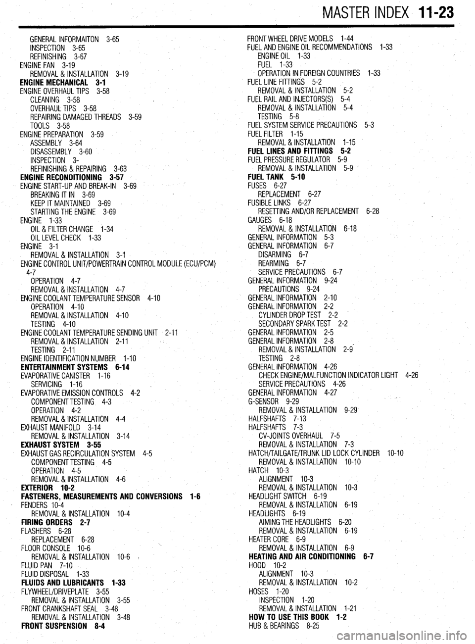
MASTER INDEX 11-23
GENERALINFORMAITON 3-65
INSPECTION 3-65
REFINISHING 3-67
ENGINE FAN 3-19
REMOVAL & INSTALLATION 3-19
ENGINE MECHANICAL 3-1
ENGINE OVERHAUL TIPS 3-58
CLEANING 3-58
OVERHAUL TIPS 3-58
REPAIRING DAMAGEDTHREADS 3-59
TOOLS 3-58
ENGINE PREPARATION 3-59
ASSEMBLY 3-64
DISASSEMBLY 3-60
INSPECTION 3-
REFINISHING & REPAIRING 3-63
ENGINE RECONDITIONING 3-57
ENGINE START-UP AND BREAK-IN
3-69
BREAKING IT IN 3-69
KEEP IT MAINTAINED 3-69
STARTING THE ENGINE 3-69
ENGINE 'l-33
OIL& FILTER CHANGE 1-34
OILLEVELCHECK 1-33
ENGINE 3-1
REMOVAL&INSTALLATION 3-l
ENGlNECONTROLUNIT/POWERTRAINCONTROLMODULE(ECU/PCM)
4-7
OPERATION 4-7
REMOVAL&INSTALLATION 4-7
ENGINECOOLANTTEMPERATURESENSOR
4-10
OPERATION 4-10
REMOVAL&INSTALLATION 4-10
TESTING 4-10
ENGINECOOLANTTEMPERATURESENDING
UNIT 2-11
REMOVAL&INSTALLATION 2-11
TESTING 2-11
ENGINE IDENTIFICATION NUMBER l-10
ENTERTAINMENT SYSTEMS 6-14
EVAPORATIVECANISTER I-16
SERVICING 1-16
' EVAPORATIVEEMISSIONCONTROLS 4-2
COMPONENTTESTING 4-3
OPERATION 4-2
REMOVAL&INSTALLATION 4-4
EXHAUST MANIFOLD 3-14
REMOVAL & INSTALLATION 3-14
EXHAUST SYSTEM 3-55
EXHAUSTGASRECIRCULATION SYSTEM
4-5
COMPONENTTESTING 4-5
OPERATION 4-5
REMOVAL&INSTALLATION 4-6
EXTERIOR 1 O-2
FASTENERS, MEASUREMENTS AND CONVERSIONS 1-6
. FENDERS 10-4
REMOVAL &INSTALLATION IO-4
FIRING ORDERS 2-7
FLASHERS 6-28
REPLACEMENT 6-28
FLOOR CONSOLE IO-6
REMOVAL& INSTALLATION IO-6 1
FLUID PAN 7-10
FLUID DISPOSAL 1-33
FLUIDS AND LUBRICANTS 1-33
FLYWHEEVDRIVEPLATE 3-55
REMOVAL & INSTALLATION 3-55
FRONT CRANKSHAFT SEAL 3-48
REMOVAL & INSTALLATION 3-48
FRONT SUSPENSION 8-4 FRONTWHEELDRIVEMODELS 1-44
FUELANDENGINEOILRECOMMENDATIONS 1-33
ENGINEOIL l-33
FUEL 1-33
OPERATION IN FOREIGN COUNTRIES
1-33
FUEL LINE FITTINGS 5-2
REMOVAL&INSTALLATION 5-2
FUEL RAIL AND INJECTORS(S)
5-4
REMOVAL &INSTALLATION 5-4
TESTING 5-8
FUELSYSTEM SERVICE PRECAUTIONS 5-3
FUELFILTER 1-15
REMOVAL&INSTALLATION l-15
FUEL LINES AND FITTINGS 5-2
FUELPRESSUREREGULATOR 5-9
REMOVAL & INSTALLATION 5-9
FUEL TANK 5-10
FUSES 6-27
REPLACEMENT 6-27
FUSIBLE LINKS 6-27 #
RESETTING AND/OR REPLACEMENT 6-28
GAUGES 6-18
REMOVAL & INSTALLATION 6-18
GENERAL INFORMATION 5-3
GENERAL INFORMATION 6-7
DISARMING 6-7
REARMING 6-7
SERVICE PRECAUTIONS 6-7
GENERAL INFORMATION 9-24
PRECAUTIONS 9-24
GENERALINFORMATION 2-10
GENERALINFORMATION 2-2
CYLINDER DROPTEST 2-2
SECONDARYSPARKTEST 2-2
GENERALINFORMATION 2-5
GENERALINFORMATION 2-8
REMOVAL &INSTALLATION 2-9'
TESTING 2-8
GENERALINFORMATION 4-26
CHECKENGlNE/MALFUNCTlONlNDlCATOR LIGHT 4-26
SERVICE PRECAUTIONS 4-26
GENERALINFORMATION 4-27
G-SENSOR 9-29
REMOVAL &INSTALLATION 9-29
HALFSHAFTS 7-13
HALFSHAFTS 7-3
CV-JOINTS OVERHAUL 7-5
REMOVAL&INSTALLATION 7-3
HATCH/TAILGATE/TRUNKLID LOCKCYLINDER lo-10
REMOVAL & INSTALLATION IO-IO
HATCH IO-3
ALIGNMENT IO-3
REMOVAL & INSTALLATION IO-3
HEADLIGHT SWITCH 6-19
REMOVAL 81 INSTALLATION 6-19
HEADLIGHTS 6-19
AIMING THE HEADLIGHTS 6-20
REMOVAL& INSTALLATION 6-19
HEATER CORE 6-9
REMOVAL&INSTALLATION 6-9
HEATING AND AIR CONDITIONING 6-7
HOOD IO-2
ALIGNMENT IO-3
REMOVAL & INSTALLATION IO-2
HOSES I-20
INSPECTION I-20
REMOVAL&INSTALLATION I-21
HOW TO USE THIS BOOK 1-2
HUB & BEARINGS 8-25
Page 406 of 408
l
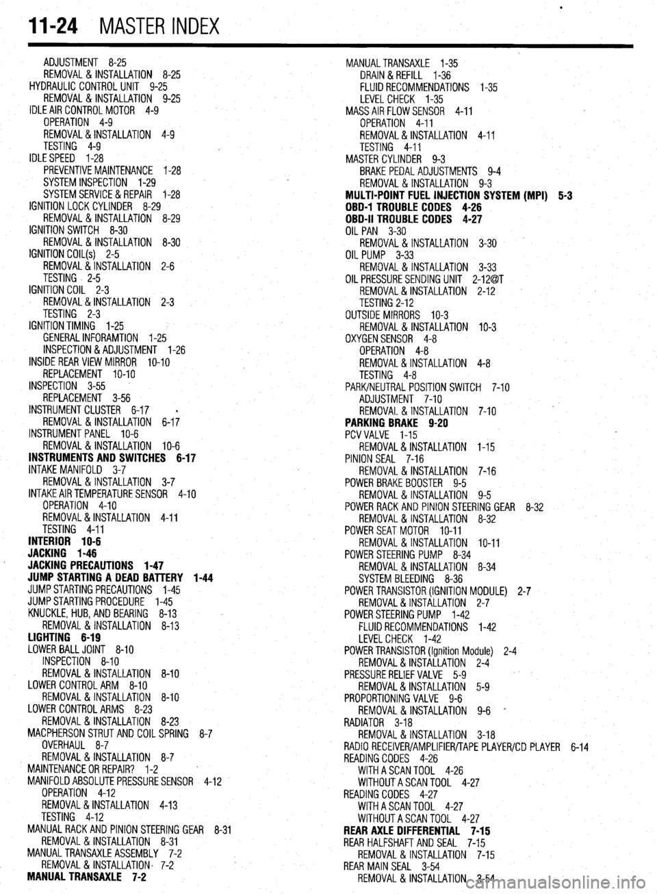
II-24 MASTER INDEX
ADJUSTMENT 8-25
REMOVAL &INSTALLATION 8-25
HYDRAULIC CONTROL UNIT 9-25
REMOVAL & INSTALLATION 9-25
IDLE AIR CONTROLMOTOR 4-9
OPERATION 4-9
REMOVAL&INSTALLATION 4-9
TESTING 4-9
IDLESPEED 1-28
PREVENTIVEMAINTENANCE 1-28
SYSTEM INSPECTION 1-29
SYSTEMSERVlCE&REPAlR 1-28
IGNITION LOCK CYLINDER 8-29
REMOVAL & INSTALLATION 8-29
IGNITION SWITCH 8-30
REMOVAL & INSTALLATION 8-30
IGNITION COIL(s) 2-5
REMOVAL&INSTALLATION 2-6
TESTING . 2-5
IGNITION COIL 2-3
REMOVAL&INSTALLATION 2-3
TESTING 2-3
IGNITION TIMING l-25
GENERALINFORAMTION l-25
INSPECTION&ADJUSTMENT l-26
INSIDE REAR VIEW MIRROR
IO-IO
REPLACEMENT IO-IO
INSPECTION 3-55
REPLACEMENT 3-56
INSTRUMENT CLUSTER 6-17
REMOVAL&INSTALLATION 6-I;
INSTRUMENTPANEL IO-6
REMOVAL &INSTALLATION IO-6
INSTRUMENTS AND SWITCHES 6-17
INTAKE MANIFOLD 3-7
REMOVAL &INSTALLATION 3-7
INTAKEAIRTEMPERATURESENSOR 4-10
OPERATION 4-10
REMOVAL&INSTALLATION 4-11
TESTING 4-11
INTERIOR 1 O-6
JACKING I-46
. JACKING PRECAUTIONS 1-47
JUMP STARTING A DEAD BATTERY 1-44
JUMPSTARTING PRECAUTIONS l-45
JUMPSTARTING PROCEDURE l-45
KNUCKLE,HUB, AND BEARING 8-13
REMOVAL &INSTALLATION 8-13
LIGHTING 6-19
LOWER BALLJOINT 8-10
INSPECTION 8-10
REMOVAL & INSTALLATION 8-10
LOWER CONTROLARM 8-10
REMOVAL&INSTALLATION 8-10
LOWER CONTROL ARMS 8-23
REMOVAL & INSTALLATION 8-23
MACPHERSONSTRUTAND COILSPRING
8-7
OVERHAUL 8-7
REMOVAL & INSTALLATION 8-7
MAINTENANCEORREPAIR? l-2
MANIFOLDABSOLUTEPRESSURESENSOR
4-12
OPERATION 4-12
REMOVAL&INSTALLATION 4-13
TESTING 4-12
MANUAL RACK AND PINION STEERING GEAR
8-31
REMOVAL & INSTALLATION 8-31
MANUALTRANSAXLEASSEMBLY 7-2
REMOVAL & INSTALLATION. 7-2
MANUAL TRANSAXLE 7-2 MANUALTRANSAXLE l-35
DRAIN &REFILL l-36
FLUID RECOMMENDATIONS l-35
LEVEL CHECK l-35
MASSAIRFLOWSENSOR 4-11
OPERATION 4-11
REMOVAL&INSTALLATION 4-11
TESTING 4-11
MASTER CYLINDER 9-3
BRAKE PEDALADJUSTMENTS 9-4
REMOVAL & INSTALLATION 9-3
MULTI-POINT FUEL INJECTION SYSTEM (MPI) 5-3
DBD-1 TROUBLE CODES 4-26
OBD-II TROUBLE CODES 4-27
OIL PAN 3-30
REMOVAL & INSTALLATION 3-30
OIL PUMP 3-33
REMOVAL & INSTALLATION 3-33
OIL PRESSURESENDING UNIT 2-12@T
REMOVAL&INSTALLATION 2-1.2
TESTING 2-12
OUTSIDE MIRRORS IO-3
REMOVAL&INSTALLATION IO-3
OXYGENSENSOR 4-8
OPERATION 4-8
REMOVAL&INSTALLATION 4-8
TESTING 4-8
PARK/NEUTRAL POSITIONSWITCH 7-10
ADJUSTMENT 7-10
REMOVAL & INSTALLATION 7-10
PARKING BRAKE 9-20
PCVVALVE l-15
REMOVAL&INSTALLATION I-15
PINION SEAL 7-16
REMOVAL &INSTALLATION 7-16
POWER BRAKEBOOSTER 9-5
REMOVAL &INSTALLATION 9-5
POWER RACK AND PINION STEERING GEAR 8-32
REMOVAL &INSTALLATION 8-32
POWERSEATMOTOR IO-11
REMOVAL & INSTALLATION IO-11
POWER STEERING PUMP 8-34
REMOVAL & INSTALLATION 8-34
SYSTEM BLEEDING 8-36
POWER TRANSlSTOR(IGNITION MODULE) 2-7
REMOVAL&INSTALLATION 2-7
POWERSTEERING PUMP l-42
FLUID RECOMMENDATIONS l-42
LEVELCHECK l-42
POWER TRANSlSTOR(Ignition Module) 2-4
REMOVAL&INSTALLATION 2-4
PRESSURERELIEFVALVE 5-9
REMOVAL&INSTALLATION 5-9
PROPORTIONING VALVE 9-6
REMOVAL & INSTALLATION 9-6 *
RADIATOR 3-18
REMOVAL &INSTALLATION 3-18
RADIO RECEIVER/AMPLIFIER/TAPE PLAYER/CD PLAYER 6-14
READING CODES 4-26
WITHASCANTOOL 4-26
WITHOUTASCANTOOL 4-27
READING CODES 4-27
WITHASCANTOOL 4-27
WITHOUTASCANTOOL 4-27
REAR AXLE DIFFERENTIAL 7-15
REAR HALFSHAFTAND SEAL 7-15
REMOVAL&INSTALLATION 7-15
REAR MAIN SEAL 3-54
REMOVAL & INSTALLATION 3-54