1900 MITSUBISHI DIAMANTE cooling water
[x] Cancel search: cooling waterPage 20 of 408
GENERALINFORMATIONAND MAINTENANCE l-21
IWSIZXJ FM. 83 A hose clamn that is taa tiaht can
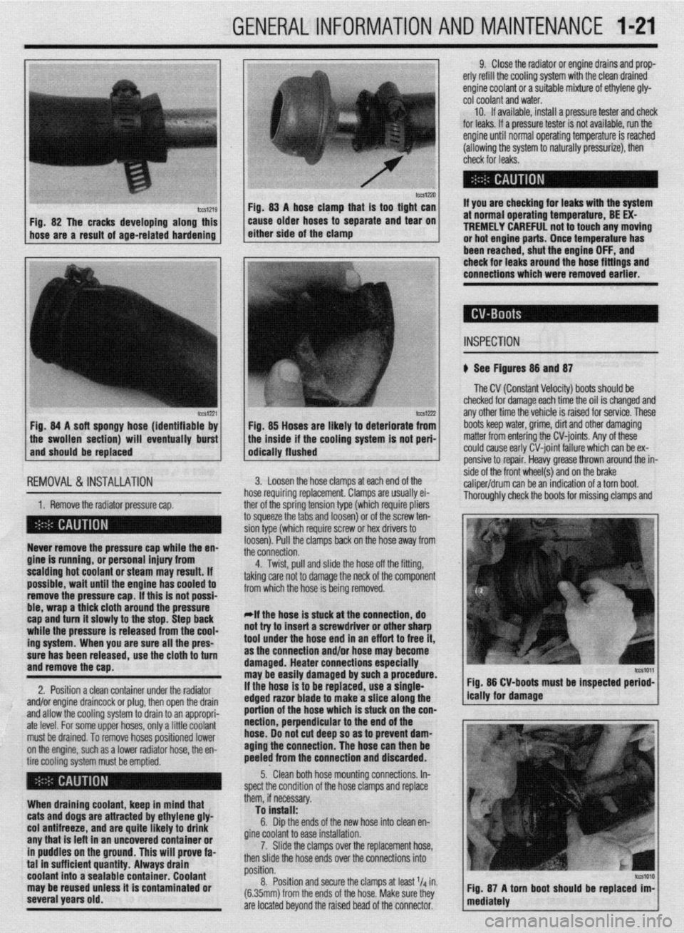
Fig. 82 The cracks developing along this
hose are a result of age-related hardening caise older hoses td separate and ‘iear on
either side of the clamp
lCCS1221 Fig. 84 A soft spongy hose (identifiable by
1 the swollen section) will eventually burst
and should be replaced
IEMOVAL &,INSTALLATION '
1. Remove the radiator pressure cap. her of the sorina tension tvoe (which reouire oliers
3 squeeze the 6bs and loosenj or of the’screw ten-
ion type (which require screw or hex drivers to
oosen). Pull the clamps back on the hose away from
he connection. Never remove the pressure cap while the en-
gine is running, or personal injury from
scalding hot coolant or steam may result. If
possible, wait until the engine has cooled to
remove the pressure cap. If this is not possi-
ble, wrap a thick cloth around the pressure
cap and turn it slowly to the stop. Step back
while the pressure is released from the cool-
ing system. When you are sure all the pres-
sure has been released, use the cloth to turn
and remove the cao.
2. Position a clean container under the radiator
and/or engine draincock or plug, then open the drain
and allow the cooling system to drain to an appropri-
ate level. For some upper hoses, only a little coolant
must be drained. To remove hoses positioned lower
on the engine, such as a lower radiator hose, the en-
tire cooling system must be emptied.
When draining coolant, keep in mind that
cats and dogs are attracted by ethylene gly-
col antifreeze, and are quite likely to drink
any that is left in an uncovered container or
in puddles on the ground. This will prove fa-
tal in sufficient quantity. Always drain
coolant into a sealable container. Coolant
may be reused unless it is contaminated or
several years old. 9. Close the radiator or engine drains and prop-
erly refill the cooling system with the clean drained
engine coolant or a suitable mixture of ethylene gly-
cot coolant and water.
10. If available, install a pressure tester and check
for leaks. If a pressure tester is not available, run the
engine until normal operating temperature is reached
(allowing the system to naturally pressurize), then
check for leaks.
If you are checking for leaks with the system
at normal operating temperature, BE EX-
TREMELY CAREFUL not to touch any moving
or hot engine parts. Once temperature has
been reached. shut the enaine OFF. and
Fig. 85 Hoses are likely to deteriorate from
the inside if the cooling system is not peri-
odically flushed check for leaks around the-hose fittings and
connections which were removed earlier.
INSPECTION
b See Figures 88 and 87
The CV (Constant Velocity) boots should be
checked for damage each time the oil is changed and
any other time the vehicle is raised for service. These
boots keep water, grime, dirt and other damaging
matter from entering the CV-joints. Any of these
could cause early CV-joint failure which can be ex-
pensive to repair. Heavy grease thrown around the in-
side of the front wheel(s) and on the brake
caliper/drum can be an indication of a torn boot.
Thorouahlv check the boots for missina clamos and 3. Loosen the hose clamps at each end of the
rose requiring replacement. Clamps are usually ei-
4. Twist, pull and slide the hose off the fitting,
sking care not to damage the neck of the component
rom which the hose is being removed.
*If the hose is stuck at the connection, do
lot try to insert a screwdriver or other sharp
ool under the hose end in an eff art to free it,
IS the connection and/or hose may become
lamaged. Heater connections especially
nay be easily damaged by such a procedure.
f the hose is to be replaced, use a single-
!dged razor blade to make a slice along the
lortion of the hose which is stuck on the con-
section, perpendicular to the end of the
lose. 00 not cut deep so as to prevent dam-
aging the connection. The hose can then be
keeled from the connection and discarded. Fig. 86 CV-boots must be inspected period-
5.. Clean both hose mounting connections. In-
,pect the condition of the hose clamps and replace
hem, if necessary.
To install:
6. Dip the ends of the new hose into clean en-
fine coolant to ease installation.
7. Slide the clamps over the replacement hose,
hen slide the hose ends over the connections into
rosition.
8. Position and secure the clamps at least l/d in.
6.35mm) from the ends of the hose. Make sure they
Ire located beyond the raised bead of the connector.
Page 38 of 408
GENERALINFORMATIONAND MAINTENANCE 1-39
leak. In most cases, you will be able to trace the leak
to a loose fitting or damaged hose.
Evaporating ethylene glycol antifreeze will have a
sweet smell and leave small, white (salt-like) de-
oosits, which can be heloful in tracino a leak. glove box and passenger side floorboard area, and
check the carpet for any signs of moisture. The
smartest way to go about finding a leak visually is to
first inspect any and all joints in the system such as
where the radiator hoses connect to the radiator and
the engine. Another thing to look for is white crusty
stains that are signs of a leak where the coolant has
6. Install the filler plug and tighten to’24 ft. Ibs.
(32 Nm).
7. If raised, carefully lower the vehicle. amount of fluid. The level should ieach thk bottom of me rating on It, lap3 1s a danciara 10 use out some
the oil filler hole. A Qss
tin,t.as ran +tw,, 4liE cars are higher. Overpressurizing the system can
lose, or worse, in the radiator or
your cooling system is con- IIC~KI LUG MU PuaJbly cause an injury or a burn if
s of a leak are probable. There the coolant is hot. Overpressurizing is normally con-
WI” U”.VlUl ,.“,,I I” 9” about finding the source of trolled by the radiator cap which has a vent valve in it
your leak. which is opened when the system reaches it’s maxi-
The first wav should be a visual insnection. Durina mum pressure rating. To pressure test the system: 7 “1sl I ly”lsJa IJ” Wll” IJU
If a the fluid level of
stantly low, the chance cause a rupture in a I:
h.n+n. nrrrn nnA . . . . ..I.
FLUID RECOMMENDATIONS the visual inspection, look around the &tire engine -
area including the radiator and the heater hoses. The *The pressure test should be performed with
the enaine OFF.
A good quality ethylene glycol based or other alu-
minum compatible antifreeze is recommended for
use in the vehicles covered by this manual. It is best
to add a 50150 mix of antifreeze and distilled water to
avoid diluting the coolant in the system. interior of the car should be inspected behind the
LEVELCHECK
recovery tank and its marking as a guideline.
*Never overfill the recovery tank.
A coolant level that consistently drops is usually a
sign of a small, hard to detect leak, although in the
worst case it could be a sign of an internal engine “_y “,~--
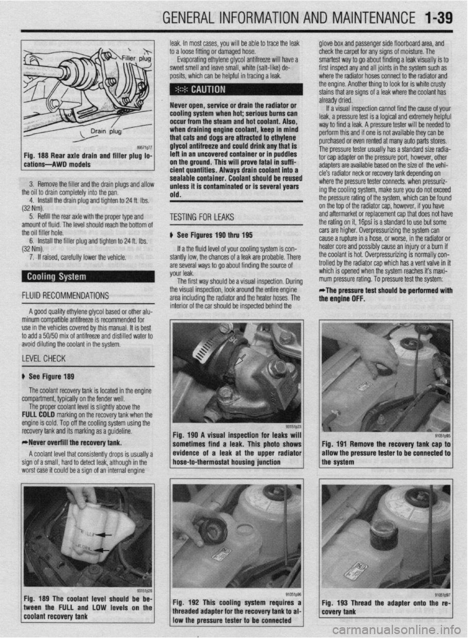
1 Fia. 190 A visual insaection for leaks will 1
sometimes find a leak. This photo shows Fig. 191 Remove the recovery tank cap to
/ * ,, / evfdence of a leak at the upper radfator
* / /the system allow the pressure tester
to be connected to hose-to-thermostat housing junction
Fig. 189 The coolant level should be be-
1 coo,ant recovery tank tween the FULL and LOW levels on the
“‘~‘_I j Fig. 192 This cooling system requires a Fig. 193 Thread the adapter onto the re-
e’ffi1pg7 / g’051p96 / 1 covety tank threaded adapter for the recovery tank to al-
low the pressure tester to
be connected
Page 40 of 408
.
GENERALINFORMATIONAND MAINTENANCE l-41
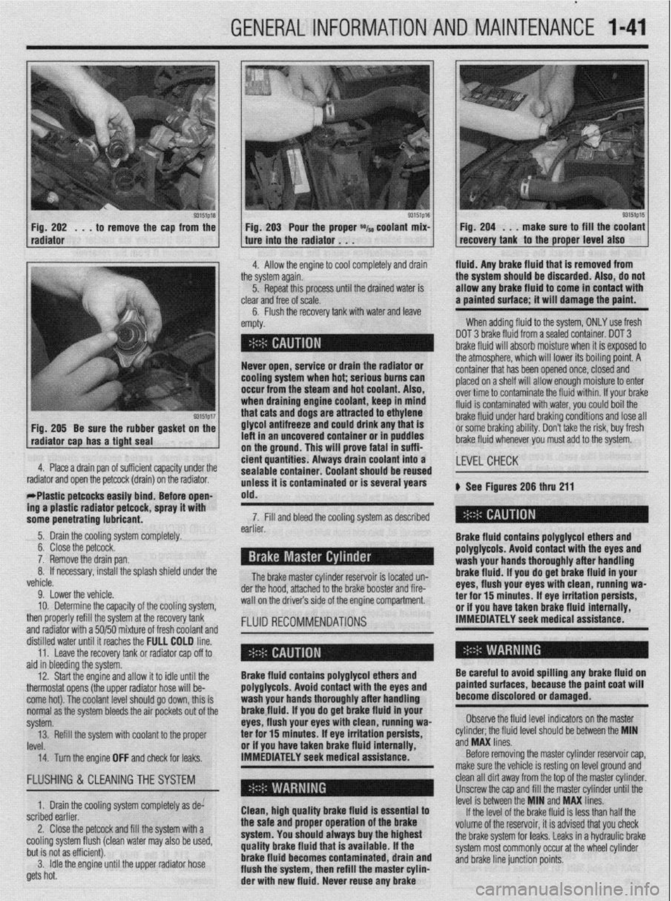
93151p18 Fig. 202 . , . to remove the cap from the
radiator
93151p17 Fig. 205 Be sure the rubber gasket on the
radiator cap has a tight seal e Fig. 203 Pour the proper *I~ coolant mix- 1 Fig. 204 . . . make sure to fill the coolant
recovery tank to the proper level also ture into the radiator . . .
.I
4. Allow the engine to cool completely and drain fluid. Any brake fluid that is removed from
ie system again.
5. Repeat this processuntil the drained water is
lear
and free of scale.
6. Flush the recovery tank with water and leave ’
mpty. the system should be discarded. Also, do not
allow any brake fluid to come in contact with
a painted surface; it will damage the paint.
When adding fluid to the system, ONLY use fresh
DOT 3 brake fluid from a sealed container. DOT 3
brake fluid will absorb moisture when it is exposed to
.a . . . , .*a. . . * .*. . .
- Never open, service or drain the radiator or
cooling system when hot; serious bums can
occur from the steam and hot coolant. Also,
when draining engine coolant, keep In mind
that cats and dogs are attracted to ethylene
glycol antifreeze and could drink any that is
left in an uncovered container or in puddles
on the ground. This will prove fatal in suffi-
4. Place a drain pan of suff i ’ 1 . . . ..I .I. 1,~ cient quantities. Always tne atmospnere, wnrcn wnr rower 1r.s oourng pomr. A
container that has been opened once, closed and
placed on a shelf will allow enough moisture to enter
over time to contaminate the fluid within. If your brake
fluid is contaminated with water, you could boil the
brake fluid under hard braking conditions and lose all
or some braking ability. Don’t take the risk, buy fresh
brake fluid whenever you must add to the system.
crenr capacrry unaer me
drain) on the radiator.
rrrasuc perwcss easuy bind; Before open-
ing a plastic radiator petcock, spray it with
some penetrating lubricant. drain coolant into a
earner. sealable container. Coolant should be reused
unless it is contaminated or is several years
old.
The brake master cylinder ~a~~~~r,~~ :A I~nnL.4 n-n 7. Fill and bleed the cooling system as described
Brake fluid contains polyglycol ethers and
polyglycols. Avoid contact with the eyes and ,LEVEL CHECK
wash your hands thoroughly after handling
brake fluid. If vou do oet brake fluid in vour
eyes, flush your eyeswith clean, runniug wa-
a-.. ‘Y-- ar -l-..n-- II -.._ I____ k See Figures 206 thru 211
.a-11-- - __-PA._ radiator and open the petcock (
- w&1--x3_ --mm.._..- . . ..-I...
5. Drain the cooling system completely.
6. Close the petcock.
7. Remove the drain pan.
If necessary, install the splash shield under the 8.
L.-l
venicie.
9. Lower the vehicle.
10. Determine the capacity of the cooling system,
then properly refill the system at the recovery tank
and radiator with a 50/50 mixture of fresh coolant and
fKm”“ll 15 IUMLC” “II- brake booster and fire- der the hood, attached to the
wall on the drivers side of the engine compartment.
FLUID RECOMMENDATIONS rer mr 13 mmures. IT eye irriIauon persim, or if you have taken brake fluid internally,
IMMEDIATELY seek medical assistance.
ala in oreerring me sysrem.
12. Start the engine and allow it to idle until the
thermostat opens (the upper radiator hose will be-
come hot). The coolant level should go down, this is
normal as the system bleeds the air pockets out of the
svstem.
IRVf!l ._._. 14. Turn the engine OFF and check for leaks. IMMEDIATELY seek medical assistance.” Brake fluid contains polyglycol ethers and
polyglycols. Avoid contact with the eyes and
wash your hands thoroughly after handling
brakefluid. If you do get brake fluid in your
eyes, flush your eyes with clean, running wa-
or if vou have taken brake fluid internallv.
Before removing the master cylinder reservoir cap,
make sure the vehicle is resting on level ground and Be careful to avoid spilling any brake fluid on
painted surfaces, because the paint coat will
become discolored or damaged.
Observe the fluid level indicators on the master
._ ._ __
‘eve1 should be between the MIN
ano
ivw unes. 13. Refill the system with coolant to the proper ter for 15 minutes; If eye irritation persists, cylinder; the tluld II
..J ..I” I....
FLUSHING & CLEANINGTHE SYSTEM
1. Drain the cooling system completely as de:
scribed earlier.
2. Close the petcock and fill the system with a
cooling system flush (clean water may also be used,
but is not as efficient).
3. Idle the engine until the upper radiator hose
gets hot. Clean, high quality brake fluid is essential to
the safe and proper operation of the brake
system. You should always buy the highest
quality brake fluid that is available. If the
brake fluid becomes contaminated, drain and
flush the system, then refill the master cylin-
der with new fluid. Never reuse any brake clean all dirt away from the top of the master cylinder.
Unscrew the cap and fill the master cylinder until the
level is between the MIN and MAX lines.
If the level of the brake fluid is less than half the
volume of the reservoir, it is advised that you check
the brake system for leaks. Leaks in a hydraulic brake
system most commonly occur at the wheel cylinder
and brake line junction points.
Page 59 of 408
.
2-12 ENGINEELECTRICAL
*This section describes the operating prina
ciples of sending units, warning lights and
gauges. Sensors which provide information
to the Enafne Control Unit (ECU) or Electronic
or Power&in Control Module (FCM/PCM) are
covered in Section 4 of this manual.
Instrument panels contain a number of indicating
devices (gauges and warning lights). These devices
are composed of two separate components. One is
the sending unit, mounted on the engine or other re-
mote part of the vehicle, and the other is the actual
gauge or light in the instrument panel.
Several types of sending units exist, however most
can be characterized as being either a pressure type
or a resistance type. Pressure type sending units
convert liquid pressure into an electrical signal which
is sent to the gauge. Resistance type sending units
are most often used to measure temperature and use
variable resistance to control the current flow back to
the indicatinq device. Both types of sendinq units are
connected inseries by a wimto the batteryithiough
the ignition switch). When the ignition is turned ON,
current flows from the battery through the indicating
device and on to the sending unit.
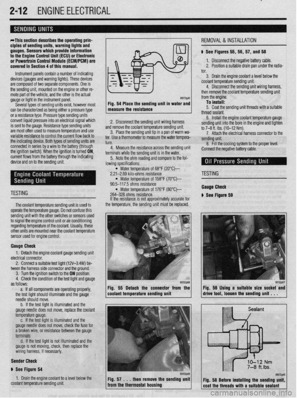
89572$43 Fig. 54 Place the sending unit in water and
measure the resistance
2. Disconnect the sending unit wiring harness
and remove the coolant temperature sending unit.
3. Place the sending unit tip in a pan of warm wa-
ter. Use a thermometer to measure the water tempera-
tl KP
L”,“.
4. Measure the resistance across the sending uni
terminals while the sending unit is in the water.
5. Note the ohm reading and compare to the fol-
lowing specifications: i, 56, 57, and 56
1. Disconnect the negative battery cable.
2. Position a suitable drain pan under the radia-
tor.
3. Drain the engine coolant a level below the
coolant temperature sending unit.
4. Disconnect the sending unit wiring harness,
then remove the coolant temperature sending unit
from the engine.
To install:
5. Coat the sending unit threads with a suitable
thread sealant.
6. Install the engine coolant temperature gauge
sending unit into the bore in the engine and tighten
to 7-8 ft. Ibs. (10-12 Nm).
7. Attach the electrical harness connector to the
sendina unit.
8. fill the cooling system to the proper level.
:onnect the negative battery cable.
l Water temperature of 68°F (2O”C)-
2.21-2.69 kilo-ohms resistance
l Water temperature of 158°F (7O’Ck
90.5-117.5 ohms resistance
TESTING l Water temperature of 176°F (8O”C)-
264-328 ohms resistance.
The coolant temperature sendina unit is used to
operate the temperature gauge. Donot confuse this
sending unit with the other switches or sensors used
to signal the engine control unit or air conditioning
regarding temperature of the coolant. Usually, these
other units are mounted near the coolant temoerature
sensor used for engine control. If the resistance is not approximately accurate for
the temperature, the sending unit must be replaced.
Gauge Check
1. Detach the engine coolant gauge sending unit
electrical connector.
2. Connect a suitable test liaht (12V-3.4W) be-
tween the harness side connector and the around.
I
3. Turn the ignition switch to the ON position.
4. Check the condition of the test light and gauge
as follows:
a. If all components are operating properly,
the test light should illuminate and the gauge
needle should move.
b. If the test light is illuminated and the
gauge needle does not move, replace the coolant
temperature gauge.
c. If the test light is illuminated and the
gauge needle does not move, check the fuse for
a broken wire, or resistance between the gauge
terminals
d. If the test light is not illuminated and the
gauge is not moving, check, then replace the
wiring harness, if necessar!y.
Sender Check
p See Figure 64
1. Drain the engine coolant to a level below the
coolant temperature sending unit Fig. 55 Detach the connector from the
coolant temperature sending unit
'ESTING
tauga Check
See Ftgure 69
Page 69 of 408
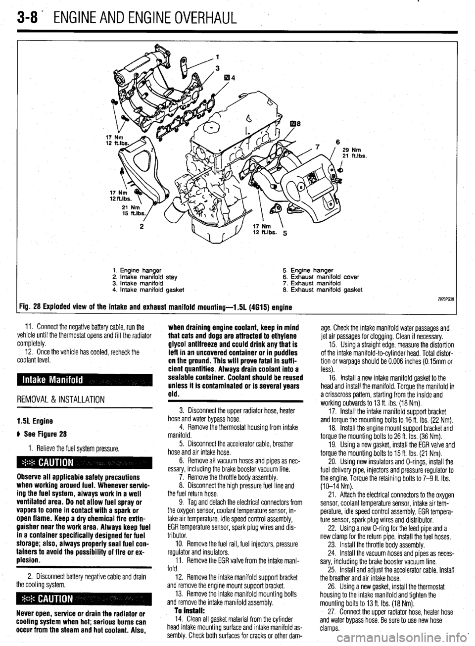
3-8' ENGINEANDENGINEOVERHAUL
Nm ft.lbs.
1. Engine hanger 5. Engine hanger
2. Intake manifold stay 6. Exhaust manifold cover
3. intake manifold 7. Exhaust manifold
4. Intake manifold gasket 8. Exhaust manifold gasket
7923ffi38 :ig. 28 Exploded view of the intake and exhaust manifold mounting-l .5L (4615) engine
11. Connect the negative battery cable, run the ,. . . .
vemcie unnl me tnermostat opens ano till the radiator
completely. age. Check the intake manifold water passages and
jet air passages for clogging. Clean if necessary.
12. Once the vehicle has cooled, recheck the
coolant level.
REMOVAL &INSTALLATION when draining engine coolant, keep in mind
that cats and dogs are attracted to ethylene
glycol antifreeze and could drink any that is
left in an uncovered container or in puddles
on the ground. This will prove fatal In suffi-
cient quantities. Always drain coolant into a
sealable container. Coolant should be reused
unless it is contaminated or is several years
old.
15. Using a straight edge, measure the distortion
of the intake manifold-to-cylinder head. Total distor-
tion or warpage should be 0.006 inches (0.15mm or
less).
16. Install a new intake manifold gasket to the
head and install the manifold. Torque the manifold in
a crisscross pattern, starting from the inside and
working outwards to 13 ft. Ibs. (18 Nm).
17. Install the intake manifold support bracket
and torque the mounting bolts to 16 ft. Ibs. (22 Nm).
18. Install the engine mount support bracket and
torque the mounting bolts to 26 ft. Ibs. (36 Nm).
19. Using a new gasket, install the EGR valve and
torque the mounting bolts to 15 ft. Ibs. (21 Nm).
20. Using new insulators and O-rings, install the
fuel delivery pipe, injectors and pressure regulator to
the engine. Torque the retaining bolts to 7-9 ft. Ibs.
(10-14 Nm).
1.51 Engine
# See Figure 28
1. Relieve the fuel system pressure.
Observe all applicable safety precautions
when working around fuel. Whenever servic-
ing the fuel system, always work in a well
ventilated area. Do not allow fuel spray or
vapors to come in contact with a spark or
open flame. Keep a dry chemical fire extin-
guisher near the work area. Always keep fuel
in a container specifically designed for fuel
storage; also, always properly seal fuel con-
tainers to avoid the possibility of fire or ex-
plosion.
2. Disconnect battery negative cable and drain
the cooling system.
Never open, service or drain the radiator or
cooling system when hot; serious burns can
occur from the steam and hot coolant. Also,
3. Disconnect the upper radiator hose, heater
hose and water bypass hose.
4. Remove the thermostat housing from intake
manifold.
5. Disconnect the accelerator cable, breather
hose and air intake hose.
6. Remove all vacuum hoses and pipes as nec-
essary, including the brake booster vacuum line.
7. Remove the throttle body assembly.
8. Disconnect the high pressure fuel line and
the fuel return hose.
9. Tag and detach the electrical connectors from
the oxygen sensor, coolant temperature sensor, in-
take air temperature, idle speed control assembly,
EGR temperature sensor, spark plug wires and dis-
tributor.
10. Remove the fuel rail, fuel injectors, pressure
regulator and insulators.
11. Remove the EGR valve from the intake mani-
fold.
12. Remove the intake manifold support bracket
and remove the engine mount support bracket.
13. Remove the intake manifold mounting bolts
and remove the intake manifold assembly.
To Install: 14. Clean all gasket material from the cylinder
head intake mounting surface and intake manifold as-
sembly. Check both surfaces for cracks or other dam- 21. Attach the electrical connectors to the oxygen
sensor, coolant temperature sensor, intake air tem-
perature, idle speed control assembly, EGR tempera-
ture sensor, spark plug wires and distributor.
22. Using a new O-ring for the feed pipe and a
new clamp for the return pipe, install the fuel hoses.
23. Install the throttle body assembly.
24. Install the vacuum hoses and pipes as neces-
sary, including the brake booster vacuum line.
25. Install and adjust the accelerator cable. Install
the breather and air Intake hose.
26. Using a new gasket, install the thermostat
housing to the intake manifold and tighten the
mounting bolts to 13 ft. Ibs. (18 Nm).
27. Connect the upper radiator hose, heater hose
and water bypass hose. Be sure to use new hose
clamps.
Page 70 of 408
ENGINEANDENGINEOVERHAUL 3-9
28. Fill the system with coolant.
29. Connect the negative battery cable, run the
vehicle until the thermostat opens, fill the radiator
completely.
30. Check and adjust the idle speed and ignition
timing.
31. Once the vehicle has cooled, recheck the
coolant level.
1.8L Engine
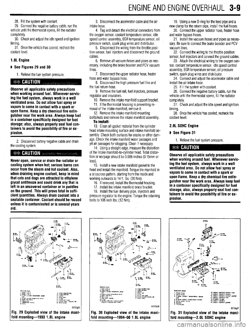
) See Figures 29 and 30
I. Relieve the fuel system pressure.
Observe all applicable safety precautions
when working around fuel. Whenever servic-
ing the fuel system, always work in a well
ventilated area. Do not allow fuel spray or
vapors to come in contact with a spark or
open flame. Keep a dry chemical fire extin-
guisher near the work area. Always keep fuel
in a container specifically designed for fuel
storage; also, always properly seal fuel con-
tainers to avoid the possibility of fire or ex-
plosion.
2. Disconnect battery negative cable and drain
the cooling system.
Never open, service or drain the radiator or
cooling system when hot; serious burns can
occur from the steam and hot coolant. Also,
when draining engine coolant, keep in mind
that cats and dogs are attracted to ethylene
glycol antifreeze and could drink any that is
leff in an uncovered container or in puddles
on the ground. This will prove fatal in suffi-
cient quantities. Always drain coolant into a
sealable container. Coolant should be reused
unless it is contaminated or is several years
old.
Fig. 29 Exploded view of the intake mani.
old mounting-1993 1.8L engine
3. Disconnect the accelerator cable and the air
intake hose.
4. Tag and detach the electrical connectors from
the oxygen sensor, coolant temperature sensor, idle
speed control assembly, EGR temperature sensor, oil
pressure switch, spark plug wires and distributor.
5. Disconnect the wiring from the throttle posi-
tion sensor, fuel Injectors and disconnect the ground
cables.
6. Remove all vacuum hoses and pipes as nec-
essary, including the brake booster and PCV vacuum
lines.
7. Disconnect the upper radiator hose, heater
hose and water bypass hose.
8. Disconnect the high pressure fuel line and
the fuel return hose.
9. Remove the fuel rail, fuel injectors, pressure
regulator and insulators.
10. Remove the intake manifold support bracket.
11. If the thermostat housing is preventing re-
moval of the Intake manifold, remove it.
12. Remove the intake manifold mounting
bolts/nuts and remove the intake manifold assembly.
To install: 13. Clean all gasket material from the cylinder
head intake mounting surface and intake manifold as-
sembly Check both surfaces for cracks or other dam-
age. Check the intake manifold water passages and
jet air passages for clogging. Clean if necessary.
14. Using a straight edge, measure the distortion
of the intake manifold-to-cylinder head. Total distor-
tion or warpage should be 0.006 inches (0.15mm or
less).
15. Install a new intake manifold gasket to the
head and install the manifold. Torque the manifold in
a crrsscross pattern, starting from the inside and
working outwards to 14 ft. Ibs. (20 Nm).
16. If removed, install the thermostat housing.
17. Install the Intake manifold brace bracket.
18. Install the fuel delivery pipe, injectors and
pressure regulator to the engine. Torque the retaining
bolts to 108 Inch Ibs. (12 Nm). 19. Using a new O-ring for the feed pipe and a
new clamp for the return pipe, install the fuel hoses,
20. Connect the upper radiator hose, heater hose
and water bypass hoses.
21. Install the vacuum hoses and pipes as neces-
sary. Be sure to connect the brake booster and PCV
vacuum lines
22. Connect the wiring to the throttle position
sensor, fuel injectors and connect the ground cables,
23. Attach the electrical wiring to the oxygen sen-
sor, coolant temperature sensor, Idle speed control
assembly, EGR temperature sensor, oil pressure
switch, spark plug wires and distributor.
24. Connect and adjust the accelerator cable and
install the air intake hose.
25. Fill the system with coolant.
26. Connect the negative battery cable, run the
vehicle until the thermostat opens, fill the radiator
completely.
27. Check and adjust the idle speed and ignition
timing.
28. Once the vehicle has cooled, recheck the
coolant level. 2.OL SOHC Engine
# See Figure 31
1. Relieve the fuel system pressure.
Observe all applicable safety precautions
when working around fuel. Whenever servic-
ing the fuel system, always work in a well
ventilated area. Do not allow fuel spray or
vapors to come in contact with a spark or
open flame. Keep a dry chemical fire extin-
guisher near the work area. Always keep fuel
in a container specifically designed for fuel
storage; also, always properly seal fuel con-
tainers to avoid the possibility of fire or ex-
plosion.
Fig. 30 Exploded view of the intake mani,
iold mounting-1994-00 1.8L engine Fig. 31 Exploded view of the intake mani
fold mounting-2.01 SOHC ermine
Page 71 of 408
3-10 ENGINEANDENGINEOVERHAUL
2. Disconnect the battery negative cable.
3. Drain the cooling system.
Never open, service or drain the radiator or
cooling system when hot; serious burns can
occur from the steam and hot coolant. Also,
when draining engine coolant, keep in mind
that cats and dogs are attracted to ethylene
glycol antifreeze and could drink any that is
left in an uncovered container or in puddles
on the ground. This will prove fatal in suffi-
cient quantities. Always drain coolant into a
sealable container. Coolant should be reused
unless it is contaminated or is several years
old.
4 Disconnect the accelerator cable and air in-
take hose.
5. Disconnect the upper radiator hose, heater
hose and water bypass hose.
6. Unplug the vacuum connection at the power
brake booster and the PCV valve if still connected.
Disconnect all remaining vacuum hoses and pipes as
necessary.
7. Disconnect the high pressure fuel line, fuel
return hose and remove throttle control cable brack-
ets
8. Tag and detach the electrical connectors from
the oxygen sensor, coolant temperature sensor,
therm0 switch, idle speed control assembly, EGR
temperature sensor, distributor, fuel injectors and
spark plug wires. Position the engine wiring harness
aside.
9. Matchmark the distributor housing to the in-
take manifold, and remove the distributor.
10. Remove the intake manifold bracket and the
engine hanger.
11. If the thermostat housing is preventing re-
moval of the intake manifold, remove it.
12. Remove the intake manifold mounting bolts
and remove the intake manifold assembly. Drsassem-
ble manifold from the Intake plenum on a work bench
as required
To install: 13. Clean all gasket material from the cylinder
head intake mounting surface and intake manifold as-
sembly. Check both surfaces for cracks or other dam-
age. Check the intake manifold water passages and
jet air passages for clogging. Clean if necessary.
14 Assemble the intake manifold assembly using
all new gaskets. Torque air intake plenum bolts to
11-14ff. Ibs. (15-19 Nm).
15. Install a new intake manifold gasket to the
head and install the manifold. Torque the manifold in
a crrsscross pattern, starting from the inside and
working outwards to 11-14 ff. Ibs. (15-19 Nm).
16. Install the fuel delivery pipe, injectors and
pressure regulator to the engine. Torque the retaining
bolts to 4 ft. Ibs (6 Nm).
17. install the thermostat housing, intake mani-
fold brace bracket, and engine hanger bracket.
18 Connect or install all hoses, cables and elec-
trical connectors that were removed or disconnected
during the removal procedure.
19. Align the distributor matchmarks and install
the distributor.
20. Fill the system with coolant,
21. Connect the negative battery cable, run the
vehicle until the thermostat opens, fill the radiator
completely. 22. Adjust the accelerator cable. Check and ad-
just the idle speed and ignition timing.
23. Once the vehicle has cooled, recheck the
coolant level.
1.6L and 2.OL DDHC Engines
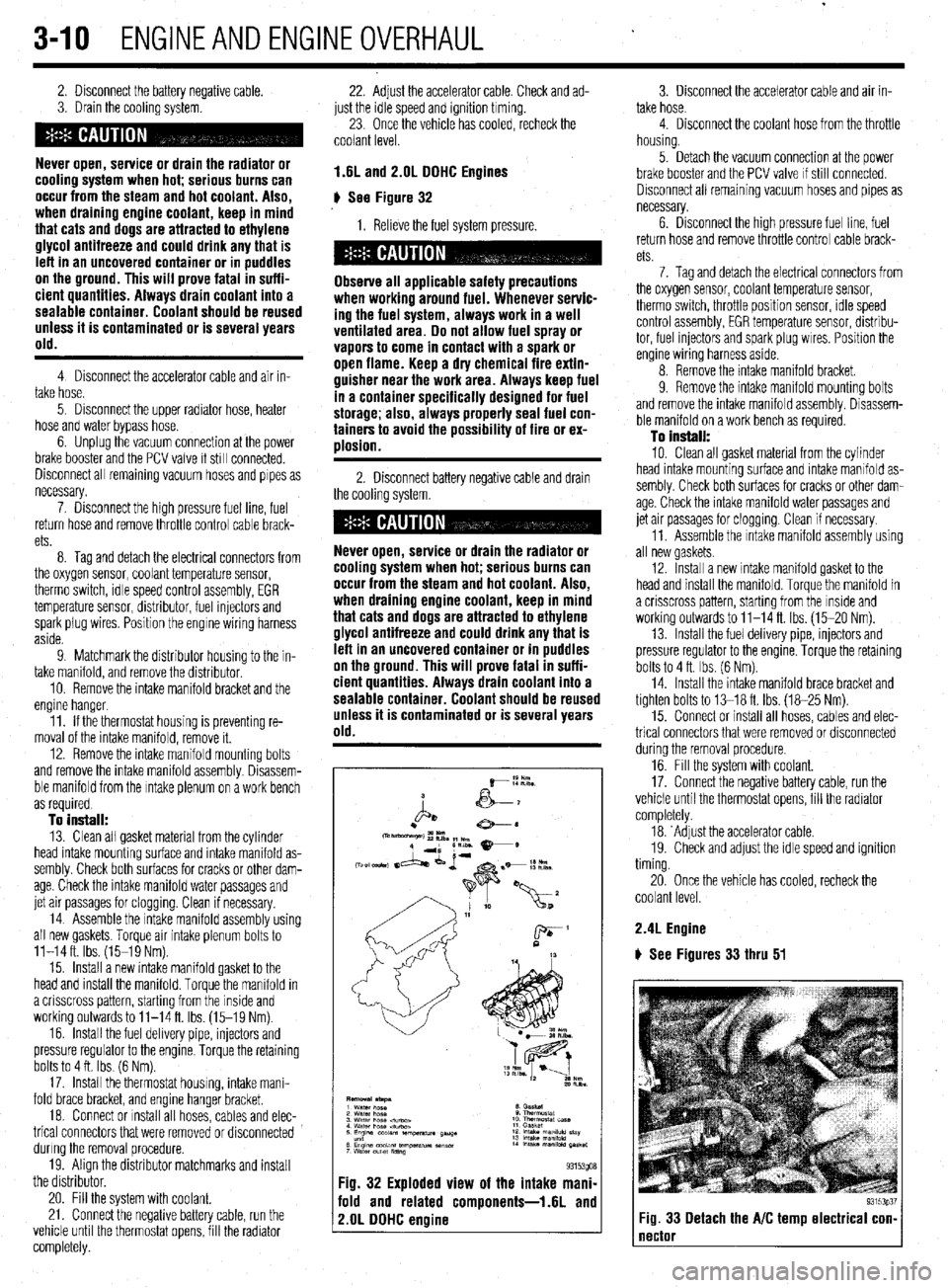
# See Figure 32
1. Relieve the fuel system pressure.
Observe all applicable safety precautions
when working around fuel. Whenever servic-
ing the fuel system, always work in a well
ventilated area. Do not allow fuel spray or
vapors to come in contact with a spark or
open flame. Keep a dry chemical fire extin-
guisher near the work area. Always keep fuel
in a container specifically designed for fuel
storage; also, always properly seal fuel con-
tainers to avoid the possibility of fire or ex-
ulosion.
2. Disconnect battery negative cable and drain
the cooling system.
Never open, service or drain the radiator or
cooling system when hot; serious burns can
occur from the steam and hot coolant. Also,
when draining engine coolant, keep in mind
that cats and dogs are attracted to ethylene
glycol antifreeze and could drink any that is
left in an uncovered container or in puddles
on the ground. This will prove fatal in suffi-
cient quantities. Always drain coolant into a
sealable container. Coolant should be reused
unless it is contaminated or is several years
old.
Fig. 32 Exploded view of the intake mani-
fold and related components-1.6L and
2.OL DDHC engine
3. Disconnect the accelerator cable and air in-
take hose.
4. Disconnect the coolant hose from the throttle
housing.
5. Detach the vacuum connection at the power
brake booster and the PCV valve If still connected.
Disconnect all remaining vacuum hoses and pipes as
necessary.
6. Drsconnect the high pressure fuel line, fuel
return hose and remove throttle control cable brack-
ets
7. Tag and detach the electrical connectors from
the oxygen sensor, coolant temperature sensor,
therm0 switch, throttle position sensor, rdle speed
control assembly, EGR temperature sensor, distribu-
tor, fuel injectors and spark plug wires. Position the
engine wiring harness aside.
8. Remove the intake manifold bracket.
9. Remove the intake mamfold mounting bolts
and remove the intake manifold assembly. Disassem-
ble manifold on a work bench as required.
To install:
10. Clean all gasket material from the cylinder
head intake mounting surface and intake manifold as-
sembly. Check both surfaces for cracks or other dam-
age. Check the intake manifold water passages and
jet air passages for clogging. Clean if necessary.
11. Assemble the Intake manifold assembly using
all new gaskets.
12. Install a new intake manifold gasket to the
head and install the manifold. Torque the manifold in
a crisscross pattern, starting from the inside and
working outwards to 11-14 ft. Ibs. (15-20 Nm).
13. Install the fuel delivery pipe, injectors and
pressure regulator to the engine. Torque the retaining
bolts to 4 ft. Ibs. (6 Nm).
14. Install the intake manifold brace bracket and
tighten bolts to 13-18 ft. Ibs. (18-25 Nm).
15. Connect or install all hoses, cables and elec-
trical connectors that were removed or disconnected
during the removal procedure.
16. Fill the system with coolant.
17. Connect the negative battery cable, run the
vehicle until the thermostat opens, fill the radiator
completely.
18. ‘Adjust the accelerator cable.
19. Check and adjust the idle speed and ignition
timing.
20. Once the vehicle has cooled, recheck the
coolant level.
2.4L Engine
) See Figures 33 thru 51
93153p37 Fig. 33 Detach the A/C temp electrical con- 1
Page 73 of 408
.
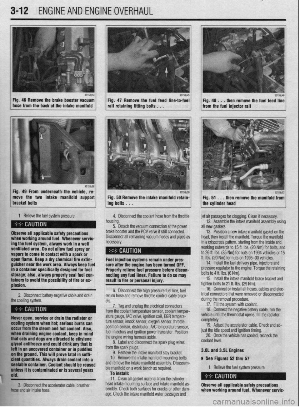
3-12 ENGINEANDENGINEOVERHAUL
93153p54
1
L Fig. 46 Remove the brake booster vacuum
hose from the back of the intake manifold Fig 47 Remove the fuel feed line-to-fuel rail’retaini”g fitti”g bo,ts . . .
Fig. 49 From underneath the vehicle, re-
move the two intake manifold support
1. Relieve the fuel system pressure.
4. Disconnect the coolant hose from the throttle
Observe all applicable safety precautions
ing the fuel system, always work in a well when working around fuel. Whenever servic-
ventilated area. Do not allow fuel spray or - __.
vapors to come in contact with a spark or
._
open flame. Keep a dry chemical fire extin-
guisher near the work area. Always keep fuel
in a container specifically designed for fuel
storage; also, always properly seal fuel con-
tainers to avoid the possibility of fire or ex-
plosion.
2. Disconnect battery negative cable and drain
the cooling rtfctnm 93153p39 Fig. 50 Remove the intake manifold retain-
ing bolts . . .
h
n ousing.
5. Detach the vacuum connection at the power
b
rake booster and the PCV valve if still connected.
C lisconnect all remaining vacuum hoses and pipes as
ecessary. et air passages for clogging. Clean if necessary.
12. Assemble the intake manifold assembly using
III new gaskets.
13. Position a new intake manifold gasket on the
lead, then install the manifold. Torque the manifold
n a crisscross pattern, starting from the inside and
vorking outwards to 15 ft. Ibs. (20 Nm) for bolts, and
o 26 ft. Ibs. (35 Nm) for nuts on 1994 vehicles or 15
t. Ibs. (20 Nr$ for nuts on 1995-00 vehicles.
14. Install the fuel delivery pipe, injectors and
xessure regulator to the engine. Torque the retaining
)olts to 4 ft. Ibs. (6 Nm). Fuel injection systems remain under pres- f
sure after the engine has been turned OFF.
Properly relieve fuel pressure before discon-
necting any fuel lines. Failure to do so may [
result in fire or personal injury.
t 6. Disconnect the high pressure fuel line, fuel
return hose and remove throttle control cable brack- t
n+C.
cm. durino the removal orocedure. 15. Install the intake manifold brace bracket and
ighten bolts to 21 ft. Ibs. (29 Nm).
16. Connect or install all hoses, cables and elec-
rical connectors that were removed or disconnected
7. Tag and unplug the electrical connectors
from the coolant temperature sensor, coolant temper- 17: Fill the system with coolant.
18 Connect the negative battery cable, run the
, . : .., ,, ., , ,
,,,, ,. ,.
93153p73 Fig. 51 . . .
then remove the manifold from
the cylinder head
Ruver open, service or drain the radiator or
@Ming system when hot; serious burns can
II&ur from the steam and hot coolant. Also,
draining engine coolant, keep in mind ’
j “thiat cats and dogs are attracted to ethylene
. . . ..____ “..” 11_,1 -...... any that is
t uncovered container or in puddles
FE ol iha ground. This will prove fatal in suff i-
k ici?M quantities. Always drain coolant into a
$1 pealable container. Coolant should be reused
h’ uniass it is contaminated or is several years
j$O'd.
**w
ature gauge, IAC valve, ignition coil, EGR tempera-
ture sensor, knock sensor, oxygen sensor, throttle
position sensor, distributor, A/C temperature sensor,
fuel injectors and ignition power transistor. Position
the engine wiring harness aside.
8. Label and disconnect the spark plug wires
from the spark plugs.
9. Remove the intake manifold stay bracket.
IO. Remove the intake manifold mounting bolts
and remove the intake manifold assembly. Disassem-
ble manifold on a work bench as required.
Tan is”.+..ll. vemcle unrn me mermosrar opens, ml tne raalaror
completely.
19. Adjust the accelerator cable. Check and ad-
just the idle speed and ignition timing.
20. Once the vehicle has cooled, recheck the
coolant level.
3.OL and 3SL Engines
ti See Figures 52 thru 57
1. Relieve the fuel system pressure.
W.>. Clean all gasket material from the cylinder
!&S head intake mounting surface and intake manifold as-
fir!: 3. Disconnect the accelerator cable, breather
Observe all applicable safety precautions
El .;,
+w..” and air intake hose. sembly. Check both surfaces for cracks or other dam-
age. Check the intake manifold water passages and when working around fuel. Whenever servic-