Page 329 of 356

u. co .... N
" N .... 0 0 :c '
Emergency situations
General
This chapter is intended for trained emergency
crews and working personnel who have the nec
essary tools and equipment to perform these
operations.
Starting by pushing or
towing
~ Note
Vehicles with an automatic transmission can
not be started by pushing or towing.
Starting with jumper
cables
If necessary, the engine can be started by con
necting it to the battery of another vehicle .
If the engine should fail to start because of a dis
charged or weak battery, the battery can be con
nected to the battery of
another vehicle, using a
pair of jumper cables to start the engine.
Jumper cables
Use only jumper cables of sufficiently large cross
section
to carry the starter current safely. Refer
to the manufacturer's specifications.
Use only jumper cables with
insulated terminal
clamps which are distinctly marked :
plus(+) cable in most cases colored red
minus(-) cable
in most cases colored black.
A WARNING -
Batteries contain electricity, acid, and gas.
Any of these can cause very serious or fatal in
jury. Follow the instructions below for safe
handling of your vehicle's battery .
-Always shield your eyes and avoid leaning
over the battery whenever possible.
-A dead battery can freeze at temperatures
around 32 °F (0 °C) . If the vehicle battery is
frozen, you must thaw it before connecting
the jump start cables. If you do not, this in-
Emergency situations
creases the risk of an explosion and chemi
cal burns. After jump starting the vehicle,
drive to an authorized Audi dealer or author ized Audi Service Facility immediately to
have the vehicle battery checked.
- Do not allow battery acid to contact eyes or
skin . Flush any contacted area with water
immediately.
- Improper use of a booster battery to start a
vehicle may cause an explosion .
- Vehicle batteries generate explosive gases .
Keep sparks, flame and lighted cigarettes
away from batteries.
- Do not try to jump start any vehicle with a
low acid level in the battery .
- The voltage of the booster battery must also
have a 12-Volt rating . The capacity (Ah) of
the booster battery should not be lower
than that of the discharged battery. Use of
batteries of different voltage or substantial
ly different "Ah " rating may cause an explo
sion and personal injury.
- Never charge a frozen battery. Gas trapped
in the ice may cause an explosion.
- Never charge or use a battery that has been
frozen. The battery case may have be weak
ened.
- Use of batteries of different voltage or sub
stantially different capacity (Ah) rating may
cause an explosion and injury. The capacity
(Ah) of the booster battery should not be
lower than that of the discharged battery.
- Before you check anything in the engine
compartment, always read and heed all
WARNINGS
c>page 272.
@ Note
- Applying a higher voltage booster battery
will cause expensive damage to sensitive
electronic components, such as control
units, relays, radio, etc.
- There must be no electrical contact between
the vehicles as otherwise current could al
ready start to flow as soon as the positive
( + ) terminals are connected.
327
Page 330 of 356

Emergency situations
@ Tips
The discharged battery must be properly con
nected to the vehicle's electrical system .
When jump starting or charging the battery,
never connect the negative ground cable to
the battery negative post because the battery
manager system must be able to detect the
battery's state of charge. Always connect the
negat ive g round cable to the negative ground
post of the battery manager control unit.
Using the jump start
cable
Both jump start cables must be connected in the
correct order!
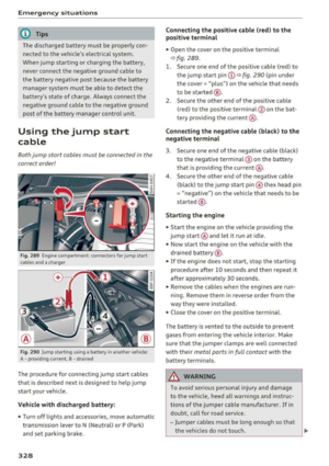
Fig. 289 E ngin e compartme nt: co nn ectors for jump start
cables and a charger
Fig. 290 Jump starting using a battery in anot her vehicle:
A
-p rov id in g current, B -drai ned
The procedure for connecting jump start cables
that is descr ibed next is designed to help jump
start your vehicle.
Vehicle with discharged battery:
~ Turn off lights and accessories, move automatic
transmission lever to N (Neutral) or P (Park)
and set parking bra ke.
328
Connecting the positive cable (red) to the
positive terminal
~ Open the cover on the positive terminal
qfig . 289.
1. Secure one end of the pos itive cable (red) to
the jump start pin
(D q fig. 290 (pin under
the cover =
"plus") on the vehicle that needs
to be started @.
2. Secure the other end of the positive cable
(red) to the posit ive terminal @on the bat
tery provid ing the cur rent @.
Connecting the negative cable (black) to the
negative terminal
3. Secure one end of the negative cable (black)
to the negative terminal @ on the battery
that is providing the current @.
4. Secure the other end of the negative cable
(black) to the jump start
pin @ (hex head pin
= "negative") on the vehicle that needs to be
started @.
Starting the engine
~ Sta rt the eng ine on the vehicle providing the
jump start @and let it run at idle.
~ Now start the engine on the vehicle with the
drained battery @.
~ If the engine does not start, stop the starting
procedure after 10 seconds and then repeat it
after approx imately 30 seconds.
~ Remove the cables when the engi nes are run
ning. Remove them in reverse order from the
way they were installed.
~ Close the cover on the posi tive terminal.
The battery is vented to the outside to prevent
gases from enter ing the vehicle interior. Make
sure that the jumper clamps are well connected
with their
metal ports in full contact with the
battery terminals .
A WARNING
-To avoid serious personal injury and damage
to the vehicle, heed all warnings and instruc
tions of the jumper cable manufacturer. If in
doubt, call for road service.
-Jumper cables must be long enough so that
the vehicles do not touch.
..,.
Page 331 of 356

-When connecting jumper cables, make sure
that they cannot get ca ught in any mov ing
parts in the engine compartment.
- Before you check anything in the engine
compartment, a lways read and heed a ll
WARNINGS
¢ page 272.
(D Note
Impro per hook-u p of jum per cables can ru in
the generato r.
- Always connect P OSITIVE( +) to POSITIV E
( + ), and NEGATIVE( -) to NEGATIVE( -)
g round post of the battery manager contro l
unit.
- Check that a ll sc rew p lugs on the battery
cells are sc rewed in firmly . If not, t ighten
pl ugs p rior to connect ing clamp on negative
b atte ry te rmi nal.
- Please note t hat the procedure fo r con nect
i ng a jumper cab le as desc ribed above ap
p lie s specifica lly to the case of yo ur vehicle
b eing ju mp starte d. When you are g iv ing a
ju mp s tart to ano ther vehicle, do
not con
n ect th e neg ative( -) ca b le to the neg ative
(-) t ermin al on t he disch arged batte ry @
¢ fig . 290. Instead, securely connect the
negat ive(- ) cab le to either a solid metal
component that is f irm ly bolted to the en
gine block o r to the engine bloc k itself. If
the battery that is be ing c ha rged does not
vent to the outs ide, escap ing batte ry gas
could ignite and ex plod e!
Towing with a tow truck
General hints
Yo ur Audi requires special h andling for towing .
The follow ing informa tion is to be used by com
mercia l tow tr uck o pera tors who know how to op
e rat e the ir equip men t sa fely.
- Never tow your Audi. Towing will cause dam
age to the engine and transmission.
- Never wrap the safety chains or winch cables
~ around the brake lines. ....
~ -To prevent unnecessary damage, your Audi N
8 must be transported with a flatbed truck. 0 :c '
Emergency situations
-To load the vehicle on to the flatbed, use the
towing loop found in the vehicle tools and at
tach to the front or rear anchorage
¢ page 329 and c> page 330.
A WARNING
A veh icle being towed is not safe for passen
ge rs. Neve r allow a nyo ne to ride in a vehicl e
b eing towed, fo r any reason.
Front towing loop
Fi g. 291 Fron t bu mpe r: removing t he cap
Fig. 292 Fron t bu mpe r: insta llin g the tow ing loop
The thread for the towing loop is on the right
s ide of the front bumper beh ind a cap.
.,. Remove the towing loo p from the vehicle too l
kit.
.,. Press the cap inward with brief, forceful pres
sure
c> fig. 291 . The cap will loosen from the
bumper.
.,. T igh ten the tow ing loop in the threaded open
ing until it stops
c> fig. 292 and t hen tighten it
w ith a wheel w re nc h .
.,. Afte r usi ng, p lace the tow ing loop b ack in the
veh icle tool kit.
IJJ>-
329
Page 332 of 356

Emergency situations
& WARNING
If the towing loop is not tightened until it
stops when installing, the threads may be
pulled out when towing the vehicle and that
could cause an accident.
Rear towing loop
Fig. 293 Rear bumper: re moving the cap
Fig. 294 Rear bumper : installi ng the towing loop
The threaded opening is located in the bumper
on the right rear side .
• Remove the towing loop from the vehicle tool
kit .
• Press the cap inward with brief, forceful pres
sure ¢
fig. 293 . The cap will loosen from the
bumper .
• Tighten the towing loop in the threaded open
ing until it
stops¢ fig. 294 and then tighten it
with a whee l wrench .
• After using, place the towing loop back in the
vehicle tool kit.
A WARNING
If the towing loop is not tightened until it
stops when installing, the threads may be
330
-
pulled out when towing the vehicle and that
could cause an accident .
Loading the vehicle onto a flatbed truck
Fig. 295 Vehicle on f latbed tru ck
Front hook up
• Align the vehicle with the centerline of the car
carrier ramp.
• Attach the winch hook to the front towline eye
previously installed.
Rear hook up
• Align the vehicle wi th the centerl ine of the car
carrier ramp.
• Attach the w inch hook to the rear towline eye
previously installed.
@ Tips
Check carefully to make sure the hook-up is
secure before moving the car up the flatbed
truck ramp.
Vehicle transport
Whenever you hove your vehicle transported, be
sure to note the following:
(D Note
Mount the tie-down chains/cables over the
running surface (ci rcumference) o f the tires.
Never secure the vehicle by the axle, the sus
pension struts or the front or rear towline
eye. For technical reasons, the pressure in the
suspension struts may change during the
transport and this will adversely affect vehicle handling.
Page 333 of 356

lL t:0 ....
"' ......
"' .... 0 0 :c '
Raising the vehicle
Lifting with workshop hoist and with floor
jack
The vehicle may only be lift ed at the lifting
points illus tr at ed.
Fig. 296 Fro nt lift in g poin t
Fig. 29 7 Rear lift ing poin t
.,. Read and heed WARNING c::> &, .
.. Activate the veh icle ja ck mode in the MMI :
I CARI funct ion button> Car systems control
button >
Servicing & checks > Air susp.: jack
mode > On .
.. Loca te lift ing po ints c::> fig . 296 and c::>fig . 297 .
.. Adju st lifting arms of wo rkshop ho ist o r floo r
ja ck t o ma tch vehicle li fting poin ts.
.. In se rt a rubb er pa d between the floor j ack/
wor kshop ho ist and the lifting points .
T he vehicle ja ck mode m ust be a ct iv a te d so th at
the au tomatic a djustment of the Ad aptive Air
Suspension does not m ake it more diffic ult to
raise the ve hicle wit h the floor jack.
If you must lift your vehicle with a floor jack to
work underneath , be sure the vehicle is safely
supported on stands intended for this purpose .
Emergency situations
Front lifting point
The lifting poi nt is locate d on the floor p an rein
f o rcement about at the same level as the ja ck
mounting point
c::> fig . 296 . Do not lift the vehi
cle at the vertical sill reinforcement .
Rear lifting point
T he lifting p oin t i s lo cate d on the ve rtic al rei n
f o rceme nt o f th e lower s ill for the on- bo ar d jac k
c::>fig. 297 .
Lifting with vehicle jack
Refer to c::> pag e 315 .
A WARNING
- To reduce the r is k of se rious inju ry and veh i
cle dama ge.
- Always lift the vehicle o nly at the specia l
wor kshop h oist a nd f loor jack lift points
il
l ustrated c::> fig. 296 and c::> fig. 297.
- Failure to lift t he ve hicle at these points
could cause the veh icle to tilt o r fall from
a lift i f there is a change in vehicle weight
dist ribution and balance . This might hap
pen, fo r example, when h eavy compo
nents such as the eng ine block o r trans
missi on are re moved .
- Whe n re mov ing heavy comp onents like
these, an ch or veh icle t o hois t or ad d co rre
spon ding weig hts t o m aintai n the cen ter of
g ravi ty . Ot herw ise, the vehicle mig ht tilt or
slip off t he hoist, caus ing se rio us pe rsonal
i njur y .
(D Note
- Be aw are of the fo llow ing po ints b efor e lift
ing the vehicle:
-The vehicle should never be lifted or
jacked up from underneath the engine oil
pan, the transmission housing, the front
or rear axle or the body side members.
This could lead to serious damage .
- To avoid damage to the underbody or
chassis frame, a rubber pad must be in
serted between the floor jack and the lift
points .
.,.
331
Page 334 of 356
Emergency situations
-Before driving over a workshop hoist,
check that the vehicle weight does not
exceed the permissible lifting capacity of
the hoist.
- Before driving over a workshop hoist, en
sure that there is sufficient clearance be
tween the hoist and low parts of the ve hicle.
332
Page 335 of 356

lL t:0 ....
"' ......
"' .... 0 0 :c '
Technical data
Vehicle specifications
XXXXX XX · X · XXXX XXX xx
®-+ IAHRZG.-IOEN T · NR. Vllllll • WIT • NO. XXXXXXXX XX X XXXXX XXX
TYP /Tffl XXX XXX
xx xxxxxxx xx xx
xx
XXX KW XXX
~ t!lll /TRANS. lllllE xxxx XXX XXX ®-t 11)10111<8./GllllkS .
©+ IAO(NR.I IN NENAllSSl.
XXXX I XXXX XXX I XX PAI NT liO./ ffT[JIQI
II. · AIJSlit / OPTIONS
EOA 7D 5 4U B 6XM SSG SR W
2 EH JO Z 1LB 1AS 1 BA
3FC S MU 7Xl
F O A 9G3 OG7 O YH OJF
TL 6 3 KA 8EH UlA X 9B OZ7
l XW
803
908 8Z4 020
7 T6 CV7
71<0 4X3 21< 2
3L4 4 KC 3YO 413 5 02
1S A 7GB
01A 4GQ
XX . X XX X XX X xxxx
Fig. 298 Vehicle ident ifica tion labe l
Vehicle Identification Number (VIN )
The VIN n umber is located in the following pla
ces :
0
0
~ :x:
- In the Infota inment system: se lect: the !CARI
func tion b utton > Car sy stem s contro l bu tton >
Serv ice
& control > VIN number .
-on the vehicle identification label
- under the w indshield on the dr iver's side
Vehicle identification label
The vehicle identification l abe l¢ fig. 298 is locat
ed in the luggage compartment under the cargo
floor cover in the spare wheel well.
The information of the vehicle identification labe l
can also be found in your Warranty
& Mainte
nance booklet.
Technical data
T he sticke r contains the fo llow ing vehicle data:
(D Vehicle Identificat ion Numbe r (VIN)
@ Vehicle type, eng ine output, transm iss ion
@ Engine and transmission codes
@ Paint and interior codes
® Optional equipment numbers
Safety compliance sticker
T he safety compliance sticker is yo ur ass ura nce
that your new veh icle complies w ith all applicable
Federal Motor Vehicle Safety Standards which
were in effect at the time the vehicle was man u
factu red. Yo u can find this st icker on the door
jamb on the driver's side. It shows the month and
year of production and the ve hicle identificat ion
numbe r of your ve hicle (perforation) as well as
t h e Gross Vehicle Weight Rat ing (GVWR) a nd the
G ross Axle We igh t Rating (GAWR).
High voltage warning label
The high voltage warning label is located in the
engine compartme nt next to the engine hood re
lease. The spark ignition system comp lies with
the Canadian standard ICES-002 .
Notes about technical
data
T he values may vary b ased on s pecial eq uipmen t
as well as market -specific equipment and meas
u ring methods .
Please note that the specifications listed in the
vehicle documen ta ti on a lways take prece den ce.
(D Tips
Missing tec hnical data was no t ava ilable at
the time of pr int ing.
333
Page 336 of 356

Technical data
Dimensions
Length (in (mm )) Width (in (mm))
Width across the Height at curb
mirrors (in (mm)) weight (in (mm))
AB L 207.3 (5,265) 76.7 (1,949) 83.l (2,111) 57.9 (1,471)
AB 202.2 (5,135) 76.7 (1,949) 83.1 (2,111) 57.5 (1,460)
58 202.6 (5,147) 76.7 (1,949) 83.l (2,111) 57.4 (1,458)
Capacities
Fuel
tank
Windshield and headlight washer system*
Weights
Gross Vehicle Weight Rating
The Gross Vehicle Weight Rating (GVWR), and
the Gross Axle Weight Rating (GAWR) for front
and rear are listed on a sticker on the door jamb
on the driver's side .
The Gross Vehicle Weight Rating includes the
weight of the basic vehicle p lus full fuel tank, oi l
and coolant, plus maximum load, which includes
passenger weight (150 lbs/68 kg per designated
seating position) and luggage
we ight¢ &..
Gross Axle Weight Rating
The Gross Ax le Weight Rating is the maximum
load that can be applied at each axle of the vehi
cle
¢ &. .
Vehicle capacity weight
The vehicle capacity weight (max. load) is listed
either on the driver's side B-pillar or inside the
fue l filler f lap .
A WARNING
- The actual Gross Axle Weight Rating at the front and rear axles should not exceed the permissible weights, and their comb inat ion
must not exceed the Gross Veh icle Weight
Rating .
334
Approximate capaci-
ties
2 1. 7 gal (82.0
L)
5.3 qt (5.0 L)
- Exceed ing permissible weight ratings can
result in vehicle damage, accidents and per
sonal injury.
@ Note
- The veh icle capacity weight figures apply
when the load is d istr ibuted evenly in the
vehicle (passengers and luggage) . When
transport ing a heavy load in the luggage
compartment, carry the load as near to the
rea r axle as possible so that the vehicle's
hand ling is not impai red.
- Do not exceed the maximum permissible
ax le loads or the maxim um gross vehicle
we ight . A lways remember that t he ve hicle's
handling will be affected by the extra load.
Th erefore, adjust your speed accordingly .
- Always observe local regulations .