Page 9 of 236
 Door handle
@
®
©
®
®
(J)
®
Central locking switch
Cent ral locking L ED ......... .. .
Side assist button
Side assist d")
00
00
......
"' ,....
"' ...... 0 0 :::,
00
(!) Door handle
@
®
©
®
®
(J)
®
Central locking switch
Cent ral locking L ED ......... .. .
Side assist button
Side assist d isplay
H eadlight cont rol sw itch .... .. .
A ir vents with thumbwheel
L ever for turn s ignal and h igh
beams .. .. .... . .......... .. .
® Multifunction ste ering wheel with :
- Horn
- Driver's airbag ........... .. .
- Driver information system con-
trols .. .. ............... .. .
- Audio , te lephone, nav igation and
vo ice recognit ion controls
- Programmable steering wheel
button . .. .. ........... .. .. .
- Rocker switches for tiptronic
mode . ... .. ... ..... ... .. .. .
@ Instrument cluster ........... .
@ Windshield washer system lever
@ I S TART EN GIN E ST OPI button .. .
@ Pa rking brake button ....... .. .
~ Starting the engine when there is a
malfunction or ignition lock . ... .
@ Steer ing whee l adjustment .... .
@ Cruise contro l lever .... ... .. .. .
@ Data link connector for On Board
Diagnostic System (OBD II) .. .. .
@ Inst rument illum ination ... .. .. .
@ Hood r ele as e .... ..... ... .. .. .
@ Automat ic luggage compartment
lid .. .. ... ............. ..... .
27
23
80
80
35
36
121
19
20
71
8
40
62
64
63
60
78
17
37
159
29
@ Power exterior mirror adjustment 38
Coc kpit o ve rv iew
@ Power windows . .. .. .. ..... .. .
@ Child safety lock ............. .
@ Buttons/indi cator lights for:
- Eme rgency flashers .. ..... .. .
- PASSENG ER AIR BAG O FF .... .
@ Infotainment system display (does
not fold away)
@ G love compartment .......... .
@ Front passenger's airbag ...... .
@ Infota inment system control panel
@ Buttons/indicator lights for:
- Drive se lect .. .. ............ .
- E lectronic Stabilization Control
( E SC) . .. .. .. .. ....... ..... .
32
31
36
128
4 7
121
83
93
- Park ing system . . . . . . . . . . . . . . 85
- Hill hold ass ist . . . . . . . . . . . . . . 94
@ Climate contro l system . . . . . . . . . 56
@ Se lector lever (automatic transm is -
sion) . . . . . . . . . . . . . . . . . . . . . . . . 67
@ Center conso le w ith:
- Cup holder . . . . . . . . . . . . . . . . . 47
- Socket . . . . . . . . . . . . . . . . . . . . . 46
- USB charging port
(D Tips
-Some the eq uipment listed here is on ly in
sta lled in certain models or is available as
an opt ion.
- The image in the instrument cluster d isplay
depends on the vehicle equipment. A maxi
mum of two versions will be pictured in th is
Owner's Manual.
- A separate operat ing manua l describes how
to operate the Infota inment system .
7
Page 10 of 236

Instruments and indicator lights
Instruments and indicator Lights
Instruments
Instrument cluster overview
The instrument cluster is the central information center for the driver.
Fig. 3 Instrument cluster overv iew
(D ISETI button .... ........... .. .
Tachometer .... .. .. ..... .... .
Engine coolant temperature gauge 9
9
8
@
®
©
®
Turn signal ind
icator lights ..... . 36
Display with :
- Indicator lights
- Driver information system
@ Speedometer
0
®
Fuel level .. .... ........... .. .
Trip odometer reset button
@ Tips
10
19
9
10
The instrument illumination for the needles
and dials turns on when the ignition is turned
on and the lights are turned off. The illumina
tion for the gauges reduces automat ica lly and
eventually turns off as brightness outside in
creases . This function reminds the driver to
turn the low beams on at the appropriate
time.
Coolant temperature indicator
The coolant temperature indicator @ c:::> page 8,
fig. 3
only operates when the ignition is switched
8
"'
"' N
0
;::) a,
"'
on. To prevent engine damage, please observe
the following notes about the temperature rang
es.
Cold range
If the needle is at the bottom of the gauge, the
engine has not reached operating temperature
yet. Avoid high eng ine speeds, full accelerating
and heavy engine loads.
Normal range
The engine has reached operating temperature
when the needle moves into the center of the
gauge under norma l driving condit ions. The nee
dle may move farther to the right on the gauge
with heavier engine load at hig h outside temper
atu res . This is no cause for concern as long as the
• indicator light in the instrument cluster does
not turn on.
If the needle is far over on the r ight side of the
gauge and the. indicator light turns o n in the
i nst rument cluster, then the coolant tempera
ture is too high
c:::>page 13.
Page 11 of 236

00
00
......
"' ,....
"' ...... 0 0 :::,
00
CD Note
- Auxiliary headlights and other accessories in
front of the cooling-air intake impair the
cooling effect of the coolant. This increases
the risk of the engine overheating during
high outside temperatures and heavy en-
gine load.
- The front spoiler also helps to distribute
cooling air correctly wh ile driving. If the
spo iler is damaged, the cooling effect will
be impai red and the risk of the engine over
heating will increase. See an authorized
A udi dealer or authori zed Aud i Service Fa
cility for assistance .
Tachometer
The tachometer displays the engine speed in rev
olutions per minute
(RPM).
You shou ld shift to the next lowest gear when
the eng ine speed is be low 1,500 RPM. The beg in
ning of the red zone in the tachometer indicates
the maximum permissible engine speed for all
gears once the engine has been broken in and
when it is warmed up to operating temperature.
Before reaching this zone, you should sh ift into
the next highest gear, select the D selector lever position, or remove your foot from the accelera
tor pedal.
CD Note
The needle in the tachometer @
Q page 8,
fig. 3 may only be in the red zone of the
gauge for a short t ime or the engine could be
damaged. The location where the red zone
begins va ries depend ing on the eng ine.
@) For the sake of the environment
Upshifting early helps you to save fuel and re
duce operating noise.
Fuel level
The fuel leve l ind icator only ope rates when the
i gnit io n is switched on. The
tD Qpage 15
turns on if the reserve quant ity of fuel is reac hed.
In strum ents an d ind ic a to r ligh ts
The fue l tank capacity of your vehicle is listed in
the Techni cal Data section
Q page 216.
(D Note
Neve r dr ive until the tank is comp lete ly emp
ty. The irregu la r supply of fuel that res ults
from that can cause engine misfires . Uncom
busted fuel w ill then enter the exhaust sys
tem. This can cause overheat ing and damage
to the catalyt ic converter.
Time/date display
You can switch between the quartz clock or the GPS controlled clock* depend ing on the vehicle
equipment. For mo re information, refe r to you r
MM I Operating Manual.
Outside temperature display
T he instrument cluster display shows the outside
temperature. At temperatures be low 42 °F ( +S
°C), a snowflake symbo l appears in front of the
temperature display.
If your vehicle is stationary or if you a re driving at
very low speeds, the temperature displayed may be slight ly higher than the actual temperature
o utside due to the heat radiating from the en
gine.
A WARNING
.-
Do not assume the roads are free of ice based
on the outside temperature d isplay. Be aware
that there may be ice on roads even when the
outside tempe rature is a round 42 °F (+5 °C)
a nd that i ce can increase t he risk of a cc idents.
(0 Tips
You can set the units used for temperature,
speed and othe r measurements in the Info
tai nment system.
9
Page 12 of 236

Instrumen ts and ind icator ligh ts
Odometer
Fig. 4 Instrument cluster: odometer
Trip odomete r and odomete r
The trip odometer @ shows the distance driven
since it was last reset. It can be used to measure
short distances .
The trip odometer can be reset to zero by press
ing the
j o.o l reset button @ c> page 8, fig. 3.
The odometer ® shows the total distance that
the vehicle has been driven.
Malfunction indicator
I f there is a malfunction in the inst rument cl us
ter,
DEF w ill appear in the trip odomete r display .
Have the malfunct ion corrected as soon as possi
ble.
Indicator lights
Description
The indicator lights in the instrument cluster
blin k or t urn on. They indicate funct ions or ma l
functions . Wi th some indicator lights, messages
may appear and war ning s ignals may sound.
Some indicator lights are shown in multiple col
ors in the inst rument cl uste r display.
Display in Driver information sy stem
The indicator lights and messages in the display
can be covered by other displays . D isplay ing driv
er messages again
c> page 19, Operating using
the windshield wiper lever,
c> page 20, Operat
ing using the multifunction steering wheel.
10
A WARNING
- Fai lure to heed wa rning lights and other im
porta nt vehicle information may result in
serious personal inj ury o r vehicle damage.
- Whenever stalled or stopped for repair,
move the vehicle a safe d istance off the
road, s top the eng ine , and turn on the
emergency f lasher
c> page 36.
-The engine compartment of a ny motor veh i
cle is a potent ia lly ha za rdous area. Before
you c hec k anything in the engine compa rt
men t, stop the eng ine and let i t cool down.
Always e xercise extreme cau tion when wor k
ing under the hood
c> page 159.
Overview
Some indicator lights t urn on brief ly as a function
check when you switch the ignition on. These sys
tems are marked with a./ in the follow ing tab les.
If one of these ind icator lights does not turn on,
there is a malfunct io n in that system.
Red indicator light s
--------------
US A models:
Brake system ./
c>page 12
Canada model s:
Brake system ./
c>page 12
USA model s:
El ec tromechanical parking brake
c> page 12
Canada model s:
E lectromechanical parking b rake
c> page 12
Cooling system
c>page 13
Engine oil pressure
c>page 13
Generator
c>page 13
Safety be lt
c>page 14
Transmission
c>page 72
Page 13 of 236

00
00
......
"' ,....
"' ...... 0 0 :::,
00
Electromechanical steering,/
¢ page 96
Steer ing lock
¢ page 14
Yellow indicator light s
"O~ I I ~ 'I
TPMS
--------------
Electronic Stabilization Control
(ESC) ,/
¢page 14
Electronic Stabili zation Control
(ESC) ,/
c>page 14
Electronic Stabilization Control
(ESC)
¢ page 92
USA models :
Anti-loc k braking system (ABS) ,/
¢page 14
Canada models:
Anti -lock braking system (ABS) ,/
¢page 14
Safety systems,/
c>page l4
Brake pads
¢page 15
Electromechanical parking brake
¢ page 12
Tire Pressu re Monitoring System*
,/
¢page 188
Tire pressure monitoring system*
¢page 188
Electronic power control,/
c>page 15
Malfunction Indicator Lamp (MIL)
./
c>page 15
Eng ine speed limitation*
¢page 15
Engine oi l level
¢ page 15
Engine oi l sensor
¢ page 15
Instruments and indicator lights
Battery charge
¢ page 13
Tank system
¢page 15
Washer fluid level*
c>page 16
Engine start system
¢page 16
Electromechanical steering./
¢page 96
Steering lock
¢page 14
Remote control key*
c>page 63
Battery in remote control key
c>page24
Bulb fa ilure indicator
c>page 16
Headlight range control system
c>page 16
Adaptive light*
c>page 16
light/rain sensor *
c>page 16
Adaptive dampers*
c>page 17
Speed warning system*
c>page 78
Canada models:
Speed warning system*
c>page 78
Other indicator lights
--------------
Turn signals
c>page 17
Trailer turn signa ls*
c> page 17
USA models:
Cruise control system
c>page 78
11
Page 14 of 236
)
Canada models:
C ruise contro l system
¢ page 78
Hill descent assist*
¢ page94
Remote control key*
¢page 63
High beams
¢page36
Door open")
Instruments and indicator lights
y>))
Canada models:
C ruise contro l system
¢ page 78
Hill descent assist*
¢ page94
Remote control key*
¢page 63
High beams
¢page36
Door open
¢page 17
Hood open
¢ page 17
Luggage compartment lid open
¢ page 17
BRAKE/(©) Brake system
If this ind icator light turns on, there is a malfunc
tion in the brake system.
llll
v ehicle and check brake fluid level
Stop the vehicle and chec k the bra ke fluid level.
See an authorized Audi dea ler or authorize d Aud i
Serv ice Facility for assistance if necessary.
1111 ( USA models )/. (Canad a model s)
Brakes : malfunction! Please stop vehicle safely
If t he A BS indica to r l ight tu) (U SA mode ls) I
[I] (Canada mode ls), t he ESC indica to r li gh t Dl.
and the bra ke sys tem ind ic a tor light 1111 (USA
mo dels)
I. (Canada mode ls) all turn on and
this message appears, then the ABS, ESC and braking distrib ution are malfunct ioning ¢ ,&. .
D o not cont inue drivi ng . See an au thorized Aud i
dea ler or a utho rized Aud i Service Facili ty for as
sistance ¢
.&..
1111 (USA models) /. (Canada models ) Park
ing brake : System fault ! See owner's manual
- If the indica to r li ght and the message appear
when the vehi cle is stationary or aft er switch
ing the ignition on ,
check if you can release the
parkin g brake . If you cannot re lease the par k
ing brake, see yo ur au thorized Audi dea ler o r
12
authorized A udi Se rvice Faci lity . If you can re
lease the parking brake and the message still
appears, see an a uthorized Audi dea ler or au
thorized Audi Service Fac ility immediately to
have the malfunction corrected.
- If the ind icator light and message appear
while
driv ing ,
the h ill start assist or emergency brak
ing function may be ma lfunctioning. It may not
be poss ible to set the parking brake or release
i t once it has been set . Do not park your vehicle
on hills. See an a uth orized Audi dea le r or a u
thorized A ud i Servi ce Facili ty for assistan ce.
App lies to : USA mode ls
If the 1111 and EIJ tur n on at the same time, the
brake pads are wo rn out ¢
page 15 .
A WARNING
-Read a nd follow the warnings in
¢ page 1 59, Working in the engine com
partment
befo re o peni ng the hoo d and
checking the brake fluid level.
- If the brake system indi cator lig ht does not
turn off or it turns on wh ile driving, t he
brake fluid leve l in the reservoir is too low,
and this increases the risk of an accident.
Stop the vehicle and do not continue driv
ing. See an authorized Aud i dea le r or a u
thorized A udi Service Fac ility for assistance .
- If the brake system indicator light turns on
together w ith the ABS and ESC indicator
lights, the ABS/ESC regu lating function may
be malfunct ion ing . Fu nctions tha t stabilize
the vehicle a re no longer available . Th is
co uld cause the vehicle to swerve, which in
creases the risk t hat the vehicle will slide.
D o not contin ue driving . See an autho rized
Aud i dea le r o r a uthorized Audi Service Facili
ty for ass istance .
PARK/(®) Electromechanical parking brake
If the -(USA mode ls) I. (Canada models)
i ndicato r light turns on, the parking brake was
set.
- (USA models ) /. (Canada mode ls ) Press
brake pedal to relea se parking brake
Ill-
Page 15 of 236

00
00
.....,
"' ,....
"' .....,
0 0 :::,
00
To release the parking brake, press the brake
pedal and press the~ button at the same time
or start driving with hill start assist
¢ page 66,
S tar ting from a s top.
rlJ Parking brake system fault! See owner's
manual
There is a malfunction in the parking brake. Drive
to an authorized Audi dealer or authorized Audi
Service Facility immediately to have the malfunc
tion corrected.
@ Tips
For additional information on the parking
brake, see
¢ page 64.
- ~- Cooling system
• Turn off engine and check coolant level.
The coolant level is too low.
Do not continue driving and switch the engine
off. Check the coolant level¢
page 166.
-If the coolan t level is too low, add coolant
¢page 166. Only continue driving once the in
dicator light turns off.
• Coolant temperature! Let engine run with
vehicle stationary.
Let the engine run at idle for a few minutes to
cool off, until the indicator light turns off.
- If the indicator light does not turn off, do not
continue driving the vehicle. See an authorized
Audi dealer or authorized Audi Service Facility
for assistance.
.&_ WARNING
- Never open the hood if you can see or hear
steam or coolant escaping from the engine compartment . This increases the risk of
burns. Wait until you no longer see or hear
steam or coolant escaping .
- The engine compartment in any vehicle can
be a dangerous area. Stop the engine and
allow it to cool before working in the engine
compartment. Always follow the informa-
-
Instruments and indicator lights
tion found in ¢ page 159, Working in the
engine compartment.
@ Note
Do not continue driving if the . indicator
light turns on -this increases the risk of en
gine damage.
• Turn off engine! Oil pressure is too low.
Stop the engine and do not continue driving.
Check the engine oil level
¢ page 164.
- If the engine oil level is too low, add engine oil
c:!;> page 164. Only continue driving once the in
dicator light turns off.
- If the engine oil level is correct and the indica
tor light still turns on, turn the engine off and
do not continue driving. See an authorized Audi
dealer or authorized Audi Service Facility for as
sistance.
(D Tips
The oil pressure warning is not an oil level in
dicator. Always check the oil level regularly .
0 Alternator/vehicle battery
• Alternator fault: Battery is not being charg
ed.
There is a malfunction in the alternator or the ve
hicle electrical system .
Drive to an authorized Audi dealer or authorized
Audi Service Facility immediately. Because the ve
hicle battery is discharging, turn off all unneces
sary electrical equipment such as the radio. See
your authori zed Audi dealer or authori zed Audi
Service Facility if the battery charge level is too
low .
r•j low battery charge: Battery will be charged
while driving.
The starting ability may be impaired.
If this message turns off after a little while, the
vehicle battery charged enough while driving. ..,_
13
Page 16 of 236

Instruments and indicator lights
If the message does not turn off, have an author
ized Audi dealer or authorized Audi Service Facili
ty repa ir the malfunction .
t Safety belt
The. indicator light stays on unti l the driver's
and front passenger's safety be lts are fastened.
Above a certain speed, there will also be a warn
ing tone .
(D Tips
For addit ional information on safety be lts,
see
¢ page 109.
@ -Steering lock
• Steering fau lt! Do not dri ve vehicle!
There is a malfunction in the electronic steering
lock . You cannot turn the ignition on.
Do
not tow your vehicle because it cannot be
steered. See an authorized Audi dealer or author
ized Audi Service Fac ility for assistance.
ell Steering lock: System fault! Ple ase contact
dealer.
There is a malfunc tion in the electronic steering
lock .
D rive to an a uth o rized Aud i dea le r or a uth orized
Aud i Serv ice Fa cility immediately to have t he
malfunct io n corre cted .
A WARNING
Do not tow your veh icle when the re is a mal
function in the electronic stee ring lock - this
increases the risk of an accident.
;;.! [J Electronic Stabilization Control (ESC)
If the bl indicator light blinks wh ile driving, the
ESC or ASR (Anti-Slip Regu lation) is actively regu
lating.
If the
bl indicato r light turns on, the system has
sw itched the ESC off. In this case, you can switch
the ignition off and then on to switch the ESC on
again . The indicator light turns off when the sys
tem is functioning fully.
14
If the II ind icator light turns on, ESC was
switched off using the
I ~ OF FI button
¢ page 92.
Stabilization con trol (ESC / ABS ): Fault! See
owne r's manual
If the GJ ind icator light and the ABS indicato r
li gh t
[El (U SA mode ls) I [iJ (Canada models)
turn on an d this message appears, there is a mal
f unction in the ABS system or electronic differen
tia l lock. This also causes the ESC to malfunction.
The brakes still function with their normal power,
but ABS is not active.
Drive to an au thorized A udi dealer or authori zed
Audi Se rvice Facility immediate ly to have the
malfunction corrected .
A WARNING
If the 1111 (USA models) • (Canada mod
e ls) brake system indicator light turns on to
gether with the ABS and ESC ind icator lights,
the ABS and ESC regulating function may have malfunctioned . Funct ions that stab ilize
the vehicle are no longer availab le. This co uld
cause the vehicle to swerve, which in cr eases
the r is k that the vehicle will slide . Dr ive care
fu lly to the nearest authorized Audi dealer or
authorized Audi Service Facility and have the malfunction corrected.
(D Tips
For addi tional in format ion on ESC and ABS,
refer to¢
page 92.
!J..' Safety systems
The E,i indicator lig ht monitors the safety sys
tems.
If the
E,i ind icator light turns on or blinks, there
i s a ma lfunction in a safety system.
D rive to an author ized A udi dealer or authori zed
Audi Se rvice Fac ility immed iate ly to have the
malfunction corrected.
 1
1 2
2 3
3 4
4 5
5 6
6 7
7 8
8 9
9 10
10 11
11 12
12 13
13 14
14 15
15 16
16 17
17 18
18 19
19 20
20 21
21 22
22 23
23 24
24 25
25 26
26 27
27 28
28 29
29 30
30 31
31 32
32 33
33 34
34 35
35 36
36 37
37 38
38 39
39 40
40 41
41 42
42 43
43 44
44 45
45 46
46 47
47 48
48 49
49 50
50 51
51 52
52 53
53 54
54 55
55 56
56 57
57 58
58 59
59 60
60 61
61 62
62 63
63 64
64 65
65 66
66 67
67 68
68 69
69 70
70 71
71 72
72 73
73 74
74 75
75 76
76 77
77 78
78 79
79 80
80 81
81 82
82 83
83 84
84 85
85 86
86 87
87 88
88 89
89 90
90 91
91 92
92 93
93 94
94 95
95 96
96 97
97 98
98 99
99 100
100 101
101 102
102 103
103 104
104 105
105 106
106 107
107 108
108 109
109 110
110 111
111 112
112 113
113 114
114 115
115 116
116 117
117 118
118 119
119 120
120 121
121 122
122 123
123 124
124 125
125 126
126 127
127 128
128 129
129 130
130 131
131 132
132 133
133 134
134 135
135 136
136 137
137 138
138 139
139 140
140 141
141 142
142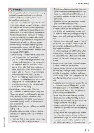 143
143 144
144 145
145 146
146 147
147 148
148 149
149 150
150 151
151 152
152 153
153 154
154 155
155 156
156 157
157 158
158 159
159 160
160 161
161 162
162 163
163 164
164 165
165 166
166 167
167 168
168 169
169 170
170 171
171 172
172 173
173 174
174 175
175 176
176 177
177 178
178 179
179 180
180 181
181 182
182 183
183 184
184 185
185 186
186 187
187 188
188 189
189 190
190 191
191 192
192 193
193 194
194 195
195 196
196 197
197 198
198 199
199 200
200 201
201 202
202 203
203 204
204 205
205 206
206 207
207 208
208 209
209 210
210 211
211 212
212 213
213 214
214 215
215 216
216 217
217 218
218 219
219 220
220 221
221 222
222 223
223 224
224 225
225 226
226 227
227 228
228 229
229 230
230 231
231 232
232 233
233 234
234 235
235