Page 201 of 236

a:,
a:,
...... N r--. N .... 0 0 ::, a:,
Changing a wheel
When you change a wheel, follow the sequence
described below step-by-step and in exactly that
order.
1. Remove the deco rative wheel co ve r* or the
whee l bolt cap s*. For more deta ils see also
c:> page 199.
2. Loosen the whee l bolt s c:> page 200.
3. Lo cate the proper mounting point for the
jack and align the jack below tha t point
<::> page 200.
4. Lift the car with the jack c:> page 200 .
5. Remove the wheel with the fl at tire and then
install the
s pare t ire c:> page 201 .
6. Tighten all wheel bolts lightly.
7 .
Low er the veh icle w ith the jack.
8 . Use the wheel bolt wrench and
firmly tighten
all wheel bolts in a crisscross pattern
c:> page 200.
9 . Replace the decorative wheel cover* o r the
whe el bolt cap s*.
_& WARNING
Always read and fo llow all WARNINGS and in
formation
c:> .&. in Raising the vehicle on
page
201 and c:> page 202.
After changing a wheel
A wheel change is not complete without the do
ing the following .
.. Always store the vehicle tool k it, the jack* and
the replaced t ire in the luggage compartmen t
c:>page 105.
.. Ch eck the tire pre ss ure of the spare tir e as soon
as possib le.
.. As soon as possible , have the
tighten ing tor
qu es
on all wheel bolts checked with a torque
wrench . The correct tightening torque is
105 ft lbs (140 Nm) .
.. Have the flat tire
replaced as soon as possible.
@ Tips
- If you notice that the wheel bolts are cor
roded and diffic ult to turn wh ile changing a
Em ergen cy a ssis tanc e
tire, they shou ld be replaced before you
check the tightening torque .
- Drive at reduced speed until yo u have the
tightening torques checked.
Removing the wheel covers/bolt caps
Fig . 153 Cha ng in g a w hee l: r emov ing t he w hee l cover
Fi g. 1 54 Cha ng in g a whee l: remov ing the w hee l bol t cap s
Wheel cover*
.. Insert the hoo k provided w ith the vehicle tool
ki t in the hole in the hub
<::> fig . 153.
.. Pull off the decorati ve wheel cover .
Wheel bolt caps*
.. Push the plast ic clip provided with the vehicle
too l kit over the wheel bolt cap until it engages
c:> fig. 154 .
.. Pull on the pla sti c clip to remove the cap .
199
Page 202 of 236

Emergency assistance
Loosening and tightening the wheel bolts
The wheel bolts must be loosened before raising
the vehicle.
Fig. 1 55 Changing a w heel : loosening the w hee l bo lts
Loosening
• Inst all the wheel bolt wrench ove r th e whee l
bolt and push it down as far as i t will go.
• Take tight hold of the
end of the wrench handle
and turn t he whee l bolts
counter-clockwise
about one single turn in the d irection of arrow
q fig . 155.
Tightening
• Install the wheel bolt wrench over the whee l
bolt and push it down as far as it will go.
• Take tight hold of the
end of the wrench handle
and turn each whee l bolt
clockw ise until it is
seated.
A WARNING
- Do not use force or hurry when changing a
wheel· you can ca use the vehicle to sl ip off
t h e jack and cause s erious pe rsonal injur ies.
- Do not loosen the whee l bolts mo re than
one turn
before you ra ise th e vehicle with
t h e ja ck .· You risk an i njur y.
(O} Tips
-Neve r use the he xagonal socket i n the han
dle of the screwd river to loosen or tighten
th e w heel bo lts.
- If a wh ee l bolt is very t ight, you may fi nd it
eas ier to loosen by carefully push ing down
on th e end of th e wh eel bo lt wren ch wi th
one
fo ot on ly. As you do so, hold on to t he
200
car to keep yo ur ba lance and ta ke c are not
to slip.
Raising the vehicle
T he vehicle must be lifted wit h the jack first be
fore the wheel can be removed .
Fig. 156 S ill pa nels: mark in gs
Fig . 157 S ill : pos it io nin g the ve hicle jack
The location of the jack po int is indicated by an
i ndenta tion o n the underside of the veh icle
q fig . 15 6.
• Activate the parking brake to prevent the vehi
cle from rolling uninte ntionally .
• Mov e the se lector lever to the P pos it ion .
• Find the
marking (imp rint) on the s ill that is
nea res t the w heel th at will be ch anged
¢ fig. 156 . Beh ind t he marking, there is a lift
ing point on t he sill fo r the ve hicle jack .
• Tur n the
vehicle jack located un der the liftin g
point o n the sill to raise the jack until the jaw
¢ fig . 157 @covers the notch on the veh icle
¢ ,& , ¢(D .
• Align the vehicle jack so the jaw@ cove rs the
no tch and the base pla te ® is fla t on t he f loor .
Th e base p late @ must be
vertical unde r the
lif ting poin t@ . ..,_
Page 203 of 236

a:,
a:,
...... N r-,. N
"" 0 0 ::, a:,
.. Install the rod on the vehicle jack: Insert the
rod into the opening on the handwheel. Turn
the rod left or r ight to secure it.
.. Cont inue raising the jack with the rod until the
wheel lifts off the ground slightly.
Position the vehicle jack
onl y under the designat
ed lifting points on the sill
c:::> fig. 156. There is ex
actly
one location for each wheel. The jack must
not be pos itioned at any other location
c:::> .&.,
c:::> CD.
Soft grou nd under the jack can cause the vehicle
to slip off the jack. Always place the jack on firm
ground . Use a flat, stable support if necessary.
Use a non-slip surface such as a rubber mat on a
s lipper y surfa ce such as tile .
_& WARNING
-
-Yo u or your passengers could be injured
wh ile chang ing a whee l if yo u do not follow
these safety precau tions:
- Position the veh icle jack only at the desig
nated lifting points and align the jack.
Otherw ise, the vehicle jack cou ld slip and
cause an injury if it does not have suffi
cient hold on the vehicle.
- Use on ly the jack* supplied with your vehi
cle to raise the vehicle.
If yo u use a jack
from a d ifferent vehicle, your veh icle may
slip off the jack -ris k of injury!
- Do not use the jack* supp lied with your ve
h icle to ra ise other veh icles, as these may
slip off the jack -ris k of injury!
- A soft or unstable s urface under the jack
may cause the vehicle to s lip off the jac k.
Always p rovide a firm base fo r the jack on
the ground . If necessary, use a sturdy
board underthejack .
- On hard, sl ippery surfa ce (such as tiles)
use a rubbe r mat or similar to prevent the
jack from slipp ing.
- T o help prevent injury to you rself and yo ur
passenge rs:
- Do not ra ise the vehicle unt il you are sure
the jack is securely engaged .
- Passengers must not remain in the vehicle
when it is jacked up.
Em ergen cy a ssis tanc e
-Make sure that passengers wait in a safe
place away from the vehicle and well away
from the road and traffic .
- Make sure jack position is correct, adjust
as necessary and then continue to raise
the jack.
- If work has to be done under the veh icle,
ensure that it is safely supported on suita
ble stands -risk of injury!
- Never start the engine when the vehicle is
on the jack -risk of acc ident!
(D Note
Do not lift the ve hicle by the s ill. Pos ition the
vehicle jack only at the des ignated lifting
po ints on the sill. Otherw ise, your veh icle will
be damaged.
Taking the wheel off/installing the spare
tire
Follow these instructions step-by-step for chang
ing the wheel.
F ig . 1 58 Chang ing a w hee l: us ing the hexagona l socket
(with the blade removed) to turn the bolts
Fig. 159 Changi ng a whee l: alig nment p in i nside the top
h ole
201
Page 204 of 236

Emergency assistance
After you have loosened a ll wheel bo lts and
raised the vehicle off the ground, remove and re
p lace the whee l as fo llows:
Removing the wheel
.,. Remove the topmost wheel bol t comp letely
with the
he xagonal socket in t he screwd river
hand le (vehicle tool kit)
¢ fig. 158 and set it
aside on a
clean s ur face.
.,. Screw the threaded end of the
alignment pin
from the tool k it hand-tight into the empty bolt
hole¢
fig. 159 .
.,. The n remove the other wheel bolts as described
above.
.,. Take off the wheel leav ing the a lignment pin in
the bo lt hole ¢ 0.
Putting on the spare tire
.,. Push the spare tire over the alig nment pin
¢ (D .
.,. Screw on the wheel bo lts and tighten them
slightly using the hex agonal socke t.
.,. Remove the a lignment pi n an d in se rt an d tight
en t he rem aining wheel bol t slightly like the
res t.
.,. Turn the jack handle counter-clockwise to lower
the ve hicle until the jack is fully re leased .
.,. Use the wheel bolt wrench to tighten all wheel
bolts firmly. Tighten them
in a crisscross pat
tern,
from one bol t to the (app roximately) op
pos ite one, to keep the whee l cente red .
.,. Perfo rm the steps req uire d afte r changing the
whee l ¢
page 199, After changing a wheel.
&, WARNING
Do not us e the he xagon al so cke t in t he screw
dr iver han dle to tig hten the wheel bol ts . I t is
not poss ib le to tighten t he bo lts to the re
quired torque usin g t he he xagonal socket -
r is k of accident!
(D Note
W hen removi ng or inst alling the whee l, the
r im cou ld hit the brake roto r and dama ge t he
rotor . Work ca ref ull y and have a seco nd per
son to help you.
202
(D Tips
- When mo unting tires with unidirectional
tread design
make sure the trea d pattern is
pointed the right way¢
page 202.
-The wheel bolts s hould be clean an d easy to
t u rn. Check fo r dirt and corrosion on the
matin g surfaces of both the wheel and the
hub. Remove all dirt from these s urfaces be
fore remounting the whee l.
Tires with unidirectional tread design
Tires with unidirectional tread design mus t be
mounted with their tread pattern pointed in the
right direction .
Using a spare tire with a tread pattern
intended for use in a specific direction
When using a s pare tire w ith a t read patter n in
te nded for use in a specif ic direct ion, please note
t h e followi ng :
- The d irection of rotation is marked by an
arrow
on the side of the tire .
-If the spare tire has to be installed in the incor
rect direction, use the spare tire on ly tempora
r il y since the tire will not be able to ac hieve its
op timum performa nce characterist ics w ith re
gard to aquap la ni ng, no ise a nd wear.
- W e recommend that you pay part icu lar atten
t ion to th is fact d urin g we t wea ther an d that
you a djust your spee d to matc h road cond i
tion s.
- Rep lace the flat tire w it h a new one an d have it
inst alled o n your ve hicle as soon as possib le to
res tore the h andlin g advan tage s of a unidir ec
tional tire .
Notes on wheel changing
Please read t he informat ion ¢ pa ge 17 8, New
tires or wheels
if yo u ar e go ing to use a spare tire
which is d ifferent from the t ires o n your ve hicle.
A ft er yo u ch an ge a tire:
- Check the tire pressure on the spare immedi-
ately after installation. .,.
Page 205 of 236

a:,
a:,
.... N r--. N .... 0 0 ::, a:,
-Ha ve the wheel b olt tightening torque
ch ecked wit h a to rque wr ench a s soon a s po s
s ible b y your auth orized Audi dealer or qu ali·
fied works hop.
- With steel and allo y wheel rims , the wheel
bolts a re correctl y tight ened at a to rque of
105
ft lbs (140 Nm ).
- If you n oti ce th at the wheel bolts are cor roded
a nd d iff icult to tu rn w hile c hang ing a t ire ,
they should be replaced be fore you check th e
t ighte nin g torqu e.
- Repla ce the flat t ire with a new one and h ave
i t insta lled on you r veh icle as so on a s possi
ble . Remo unt the whee l co ver .
Until then, d riv e with extra ca re and at redu ced
spee ds.
A WARNING
- If you are going to equ ip your vehicle w ith
t ir es or rims which differ from those which
were factory installed, then be sure to read
the informat io n
¢ page 178, N ew tires or
wheels.
- Always make sure the damaged wheel or
even a flat tire and the jack and tool kit a re
properly secured in the luggage compart
ment and are not loose in the passenger
compartmen t.
- In an accident o r sudden maneuver they
cou ld fly forward, injuring anyone in the ve
hicle.
- Always store damaged whee l, ja ck a nd too ls
sec urely in the luggage compartment . Oth
erwise, in an accident or sudden maneuver
they could fly forward, ca using injury to pas
sengers in the vehicle .
(D Note
Do not use commercia lly available tire seal
ants . Otherwise, the electrical components of
the t ire pressure monitoring system* will no
longer work properly and the sensor for the
tire pressure mon itor ing system" will have to
be replaced by qualified workshop.
.
Em ergen cy a ssis tanc e
Spare tire
Space-saving spare tire (compact spare
tire)
Applies to: veh icles with spare tir e/space-saving spare tire
(compact spare tire)
F ig. 160 Lugg age compar tme nt: space -s a ving s pare tire
( c ompact spa re
tir e)
The spare tire is intended fo r sh ort -term use on
ly. Have the damaged tire checked and replaced ,
i f necessary, by an authorized Aud i dea ler or au
thorized Aud i Service Facility as soon as possible.
T here are some restr ictions on the use of the
compact spare tire . The compac t spa re t ire has
been designed specifically for your type of vehi
cle . Do not rep lac e it with the spare tire from an
other type of vehicle .
Removing the spare tire
.,. Remove the cargo floo r.
.,. Remove the w ing bo lt
¢ fig. 160 an d then re-
move the retaine r underneath it .
.,. Remov e the subwoofer*
¢ page 204.
.,. Remov e the spar e tir e.
Snow chains
For technical reasons, the use of snow chains on
the compact spare tire is not pe rmitted .
If you have to drive with snow chains and a front
tire fails , mo unt the spare wheel in place of a
rear tire. Install the snow chains o n the rear t ire
that you removed, and install that in place of the
front t ire that fai led .
A WARNING
-Never use the spare tire if it is damaged or if
it is worn down to the tread wear indicators . .,.
203
Page 206 of 236

Emerg ency assis ta nce
- If the spare tire is more than 6 years old,
use it only in an emergency and with ex
treme caution and careful driving.
- The spare tire is intended only for tempora
ry and short-term use .
It should be replaced
as soon as possible with the normal wheel
and t ire .
- After mounting the compact spare tire, the
tire pressure must be checked as soon as
poss ible. The tire pressure of the compact
spare tire must be
4.2 bar; otherwise, you
risk having an accident.
- Do not drive faster than SO mph
(80 km/h).
Yo u risk having an accident.
- Avoid full-throttle accelerat ion, heavy brak
ing, and fast cornering . You risk having an
acc ident.
- Never dr ive using more than one spare
wheel and tire . You risk having an accident .
- Normal summer or winter tires must not be mounted on the compact spare wheel rim.
- For technical reasons, the use of tire chains
on the spare tire is not perm itted. If it is
necessary to drive with t ire chains, the spare
wheel m ust be mounted on the front axle in
the event of a flat in a rear tire. The new ly
available front wheel m ust then be insta lled
in place of the rear wheel with the flat tire.
Installing the tire chain before mounting
the wheel and t ire is recommended.
- Loose items in the passenger compartment
can cause serious perso nal injury during
hard braking or in an accident. Never store
the spare tire or jack and too ls in the pas
senger compartment.
204
Removing the subwoofer
App lies to : vehicles wit h subwoofer
The subwoofer must be removed before the
spare tire*ltemporary spare tire* can be re moved.
Fig . 161 Spare whee l we ll: subwoofe r
Removing th e subwoo fer
.. Remove the cargo floor .
.. Press the connector
tabs @¢fig . 161 togeth
er .
.. Remove the connector @and set the discon
nected cable aside.
.. Remove the wing bo lt and then remove the re-
tainer underneath it .
.,. Carefully remove the s ubwoofer .
Insta llin g the sub woofer
.. Carefully place the subwoofer in the rim well.
The word "FRONT" on the subwoofer must face
forward.
.. Insert the connector that was removed .
.,. Secure the subwoofer with the w ing bo lt.
.. Reinse rt the cargo floor .
Page 207 of 236

Fuses and bulbs
Electrical fuses
Replacing fuses
A fuse that has blown will have metal strips that
have burned through .
Fig. 162 Dr iver's side of th e cockpit: fold ing the storage
co mpartme nt down
Fig . 16 3 Engine compar tmen t: removing the fuse pane l
cover
The fuses are located in the driver 's side foo twell
be hind the storage compartment and in the en
g ine compartment .
Preparations
.. Switch the ign ition and all e lectr ica l equi pment
off.
.. Check the following table to see which fuse be -
l ongs to the equipment .
Fuses behind the storage compartment
.. Open the storage compartmen t.
.. Press t he left and r igh t re tainers inward and
fold the compartment all the way dow n
oo ¢fig. 162. a:, ...... N ~ Fuses in the engine compartment
'"' 0 g .. Open the hood ¢ page 159.
a:,
Fuses and bulbs
.. To re lease the fuse panel cove r, slide both s lid
ing retainers at the left and right forward
¢fig . 163 .
.. Remove the fuse panel cover.
Replacing fuses
T he clamp is loca ted below the f uses beh ind the
storage compartment (d river's side) .
.. Fold t his compa rtme nt all the way down a nd
remove t he cl amp from the ho lder .
.. Remove the co lored plas tic clip from the fuse
pane l, if necessary . You can d ispose o f the p las
tic clip .
.. Remove the fuse using the clamp .
.. Rep lace the blown fuse only with an identical
new one .
.. Insta ll the cover.
Fuse color identifi cation
Color Current rating
in amps
Black 1
P urple 3
Light brown 5
Brown 7.5
Red 10
Blue 15
Ye llow 20
W hite or transpa rent 25
Green 30
O range 40
A WARNING
Do not repair fuses and never rep lace a blown
f u se wit h one that has a hig her amp rat ing .
This can cause damage to the e lectr ica l sys
tem and a fir e.
(D Note
If a new fuse burns out again shortly after you
have insta lled it, have the electrical system
checked as soon as poss ible by an author ized
A udi dealer or au tho rized Aud i Service Fac ili
ty.
205
Page 208 of 236

Fuses and bulbs
(D Tips
- The following table does not list fuse loca
tions that are not used.
- Some of the equipment listed in the follow
ing tables applies only to certain model ver
sions or certain optional equipment.
Cockpit fuse assignment
The fuse number is stamped into the plastic be
low or above each fuse.
No. Equipment
1 LED headlight (left)
2 LED headlight ( right)
5 LED headlight (left)
6 LED headlight (right)
7 Steering lock
8 Convenience access contro l module
9
Airbag control module, AIRBAG OFF indi-
cator light
12
Transmission control module, selector
mechanism
Air quality sensor for cl imate control sys-
tern, heated w indow washer nozzles ,
lj]
button, reverse light button<®>, oi l level
13 sensor, climate contro l system, seat occu-
pant detection system, seat heating, but-
tons in the center console, automatic dim-
ming mirror
Engine control module, quattro control
modu le, transmission control module,
14
brake lights, electromechanica l steering,
Gateway control module, trai ler hitch con-
trol module, ESC contro l module, light
switch, damping control module
Headlight range control module , instru-
ment illumination, headlights (left, right),
15 diagnostic connector, crankcase housing
heater, a ir flow sensor, socket relay, DC/
DC converter
16 Park ing aid
17 Parking system rearview camera
18 TV tuner
19 Engine starter control, DC/DC converter
206
No . Equipment
20
ESC contro l module, climate/heating con-
trol, special functions interface
21 Selector mechanism power supply
22 Interior monitoring
© button, front interior lighting buttons,
23 diagnostic connector, light switch, light/
rain sensor, humidity sensor
25 Headlight power supply
26 Rear window wiper
27 Starter system
28 Infotainment system
29
Supply for the parking system rearv iew
camera and TV tuner
30 Infotainment system
31 Infotainment system
32 Instrument cluster
33 A utomat ic dimming rearview mirror
36
Cigarette lighter, cockpit/luggage com-
partment socket
37 Cockpit/rear socket
38 Transmission control module
40 Trailer hitch control module
41 Tra iler hitch control module
42 Trailer hitch control module
44 Rear window defogger
45
Electromechanical parking brake control
module
46 Trailer hitch control module
47 quattro control module
48 Aut omat ic lu ggage compartment lid con-
tro l module
so Blower
51
Electromechanical parking brake control
module
52 BCM
53 Fr ont seat heating
54 Panorama roof
SS Sun shade on the panorama
roof
56 Adaptive dampers control module
 1
1 2
2 3
3 4
4 5
5 6
6 7
7 8
8 9
9 10
10 11
11 12
12 13
13 14
14 15
15 16
16 17
17 18
18 19
19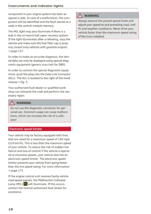 20
20 21
21 22
22 23
23 24
24 25
25 26
26 27
27 28
28 29
29 30
30 31
31 32
32 33
33 34
34 35
35 36
36 37
37 38
38 39
39 40
40 41
41 42
42 43
43 44
44 45
45 46
46 47
47 48
48 49
49 50
50 51
51 52
52 53
53 54
54 55
55 56
56 57
57 58
58 59
59 60
60 61
61 62
62 63
63 64
64 65
65 66
66 67
67 68
68 69
69 70
70 71
71 72
72 73
73 74
74 75
75 76
76 77
77 78
78 79
79 80
80 81
81 82
82 83
83 84
84 85
85 86
86 87
87 88
88 89
89 90
90 91
91 92
92 93
93 94
94 95
95 96
96 97
97 98
98 99
99 100
100 101
101 102
102 103
103 104
104 105
105 106
106 107
107 108
108 109
109 110
110 111
111 112
112 113
113 114
114 115
115 116
116 117
117 118
118 119
119 120
120 121
121 122
122 123
123 124
124 125
125 126
126 127
127 128
128 129
129 130
130 131
131 132
132 133
133 134
134 135
135 136
136 137
137 138
138 139
139 140
140 141
141 142
142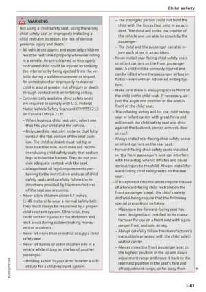 143
143 144
144 145
145 146
146 147
147 148
148 149
149 150
150 151
151 152
152 153
153 154
154 155
155 156
156 157
157 158
158 159
159 160
160 161
161 162
162 163
163 164
164 165
165 166
166 167
167 168
168 169
169 170
170 171
171 172
172 173
173 174
174 175
175 176
176 177
177 178
178 179
179 180
180 181
181 182
182 183
183 184
184 185
185 186
186 187
187 188
188 189
189 190
190 191
191 192
192 193
193 194
194 195
195 196
196 197
197 198
198 199
199 200
200 201
201 202
202 203
203 204
204 205
205 206
206 207
207 208
208 209
209 210
210 211
211 212
212 213
213 214
214 215
215 216
216 217
217 218
218 219
219 220
220 221
221 222
222 223
223 224
224 225
225 226
226 227
227 228
228 229
229 230
230 231
231 232
232 233
233 234
234 235
235