2016 NISSAN NOTE fuse diagram
[x] Cancel search: fuse diagramPage 3551 of 3641

WCS-36
< DTC/CIRCUIT DIAGNOSIS >
POWER SUPPLY AND GROUND CIRCUIT
1.CHECK FUSES AND FUSIBLE LINK
Check that the following fuses and fusible link are not blown.
Is the fuse blown?
YES >> Replace the blown fuse or fusible link after repairing the affected circuit.
NO >> GO TO 2.
2.CHECK POWER SUPPLY CIRCUIT
1. Disconnect BCM connector M99.
2. Check voltage between BCM connector M99 and ground.
Is the inspection result normal?
YES >> GO TO 3.
NO >> Repair harness or connector.
3.CHECK GROUND CIRCUIT
Check continuity between BCM connector M99 and ground.
Is the inspection result normal?
YES >> Inspection End.
NO >> Repair harness or connector.
BCM (BODY CONTROL SYSTEM) (WIT HOUT INTELLIGENT KEY SYSTEM)
BCM (BODY CONTROL SYSTEM) (WITHOUT INTELLIGENT KEY SYSTEM) : Diag-
nosis Procedure
INFOID:0000000012542993
Regarding Wiring Diagram information, refer to BCS-117, "Wiring Diagram".
1.CHECK FUSES AND FUSIBLE LINK
Check that the following fuses and fusible link are not blown.
Terminal No. Signal nameFuses and fusible link No.
57 Battery power supply 12 (10A)
70 G (40A)
BCM
Ground Voltage
Connector Terminal
M99 57
— Battery voltage
70
BCM GroundContinuity
Connector Terminal
M99 67—Yes
Terminal No. Signal nameFuses and fusible link No.
37 Battery power supply 8 (10A)
42 12 (10A)
50 G (40A)
11 Ignition switch ACC or ON 18 (10A)
38 Ignition switch ON or START 2 (10A)
Revision: August 2015 2016 Versa Note
cardiagn.com
Page 3560 of 3641

WCS
KEY SWITCH SIGNAL CIRCUIT (WITHOUT INTELLIGENT KEY)
WCS-45
< DTC/CIRCUIT DIAGNOSIS >
C
D E
F
G H
I
J
K L
M B A
O P
KEY SWITCH SIGNAL CIRCUIT (WITHOUT INTELLIGENT KEY)
DescriptionINFOID:0000000012432706
Transmits a key switch signal to the BCM.
Component Function CheckINFOID:0000000012432707
1. CHECK BCM INPUT SIGNAL
Select Data Monitor for BCM and check the KEY ON SW monitor value.
Is the inspection result normal?
YES >> Inspection End.
NO >> Refer to WCS-45, "
DiagnosisProcedure".
Diagnosis ProcedureINFOID:0000000012432708
Regarding Wiring Diagram information, refer to WCS-26, "Wiring Diagram".
1. CHECK FUSE
Check if the key switch 10A fuse [No. 8, located in the fuse block (J/B)] is blown.
Is the fuse blown?
YES >> Replace the fuse after repairing the affected circuit.
NO >> GO TO 2.
2. CHECK BCM INPUT SIGNAL
Check voltage between BCM harness connector M18 terminal 37 and ground.
Is the inspection result normal?
YES >> Inspection End.
NO >> GO TO 3.
3. CHECK KEY SWITCH CIRCUIT
1. Disconnect BCM connector M18 and key switch.
2. Check continuity between BCM harness connector M18 terminal 37 and key switch harness connector M27 terminal 1.
3. Check continuity between BCM harness connector M18 terminal 37 and ground.
Monitor Item Condition Status
KEY ON SW When key is removed from key cylinder
OFF
When key is inserted into key cylinder ON
Te r m i n a l s
ConditionVol tag e
(Approx.)
(+)
(−)
BCM
connector Te r m i n a l
M18 37Ground Key is inserted
Battery voltage
Key is removed 0V
BCM Key switch
Continuity
Connector TerminalConnector Terminal
M 183 7M 27 1 Y es
Revision: August 2015 2016 Versa Note
cardiagn.com
Page 3566 of 3641

WW-1
DRIVER CONTROLS
C
DE
F
G H
I
J
K
M
SECTION WW
A
B
WW
N
O P
CONTENTS
WIPER & WASHER
PRECAUTION ....... ........................................3
PRECAUTIONS .............................................. .....3
Precaution for Supplemental Restraint System
(SRS) "AIR BAG" and "SEAT BELT PRE-TEN-
SIONER" ............................................................. ......
3
Procedure without Cowl Top Cover .......................3
Precaution for Work ..................................................3
PREPARATION ............................................5
PREPARATION .............................................. .....5
Special Service Tools .......................................... ......5
Commercial Service Tool ..........................................5
SYSTEM DESCRIPTION ..............................6
COMPONENT PARTS ................................... .....6
Component Parts Location .................................. ......6
SYSTEM ..............................................................8
FRONT WIPER AND WASHER SYSTEM ............. ......8
FRONT WIPER AND WASHER SYSTEM : Sys-
tem Diagram ..............................................................
8
FRONT WIPER AND WASHER SYSTEM : Sys-
tem Description .........................................................
8
FRONT WIPER AND WASHER SYSTEM : Fail-
Safe .........................................................................
10
REAR WIPER AND WASHER SYSTEM ............... ....10
REAR WIPER AND WASHER SYSTEM : System
Diagram ...................................................................
10
REAR WIPER AND WASHER SYSTEM : System
Description ..............................................................
10
DIAGNOSIS SYSTEM (BCM) (WITH INTELLI-
GENT KEY SYSTEM) .........................................
13
COMMON ITEM ..................................................... ....13
COMMON ITEM : CONSULT Function (BCM -
COMMON ITEM) .....................................................
13
WIPER .................................................................... ....14
WIPER : CONSULT Function (BCM - WIPER) .......14
DIAGNOSIS SYSTEM (BCM) (WITHOUT IN-
TELLIGENT KEY SYSTEM) .............................
15
COMMON ITEM ..................................................... ....15
COMMON ITEM : CONSULT Function (BCM -
COMMON ITEM) .....................................................
15
WIPER .................................................................... ....16
WIPER : CONSULT Function (BCM - WIPER) .......16
DIAGNOSIS SYSTEM (IPDM E/R) ...................17
Diagnosis Description ..............................................17
CONSULT Function (IPDM E/R) .............................18
ECU DIAGNOSIS INFORMATION ..............21
BCM, IPDM E/R .................................................21
List of ECU Reference ......................................... ....21
WIRING DIAGRAM ......................................22
FRONT WIPER AND WASHER SYSTEM ........22
Wiring Diagram .................................................... ....22
REAR WIPER AND WASHER SYSTEM ..........28
Wiring Diagram ........................................................28
BASIC INSPECTION ...................................33
DIAGNOSIS AND REPAIR WORKFLOW ........33
Work Flow ............................................................ ....33
DTC/CIRCUIT DIAGNOSIS .........................35
WIPER AND WASHER FUSE ...........................35
Description ........................................................... ....35
Diagnosis Procedure ...............................................35
FRONT WIPER MOTOR LO CIRCUIT ..............36
Component Function Check ....................................36
Diagnosis Procedure ...............................................36
Revision: August 2015 2016 Versa Note
cardiagn.com
Page 3601 of 3641

WW-36
< DTC/CIRCUIT DIAGNOSIS >
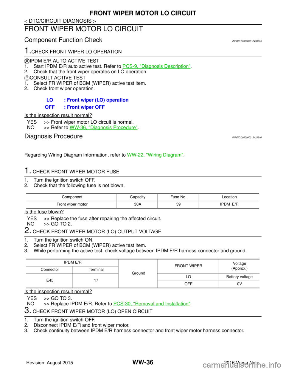
FRONT WIPER MOTOR LO CIRCUIT
FRONT WIPER MOTOR LO CIRCUIT
Component Function CheckINFOID:0000000012433215
1.CHECK FRONT WIPER LO OPERATION
IPDM E/R AUTO ACTIVE TEST
1. Start IPDM E/R auto active test. Refer to PCS-9, "
Diagnosis Description".
2. Check that the front wiper operates on LO operation.
CONSULT ACTIVE TEST
1. Select FR WIPER of BCM (WIPER) active test item.
2. Check front wiper operation.
Is the inspection result normal?
YES >> Front wiper motor LO circuit is normal.
NO >> Refer to WW-36, "
Diagnosis Procedure".
Diagnosis ProcedureINFOID:0000000012433216
Regarding Wiring Diagram information, refer to WW-22, "Wiring Diagram".
1. CHECK FRONT WIPER MOTOR FUSE
1. Turn the ignition switch OFF.
2. Check that the following fuse is not blown.
Is the fuse blown?
YES >> Replace the fuse after repairing the affected circuit.
NO >> GO TO 2.
2. CHECK FRONT WIPER MOTOR (LO) OUTPUT VOLTAGE
1. Turn the ignition switch ON.
2. Select FR WIPER of BCM (WIPER) active test item.
3. While performing the active test, check vo ltage between IPDM E/R harness connector and ground.
Is the inspection result normal?
YES >> GO TO 3.
NO >> Replace IPDM E/R. Refer to PCS-30, "
Removal and Installation".
3. CHECK FRONT WIPER MOTOR (LO) OPEN CIRCUIT
1. Turn the ignition switch OFF.
2. Disconnect IPDM E/R and front wiper motor.
3. Check continuity between IPDM E/R harness connector and front wiper motor harness connector.
LO : Front wiper (LO) operation
OFF : Front wiper OFF
Component CapacityFuse No. Location
Front wiper motor 30A39 IPDM E/R
IPDM E/R
GroundFRONT WIPER
Vo l ta g e
(Approx.)
Connector Terminal
E45 17 LO
Battery voltage
OFF 0V
Revision: August 2015 2016 Versa Note
cardiagn.com
Page 3603 of 3641

WW-38
< DTC/CIRCUIT DIAGNOSIS >
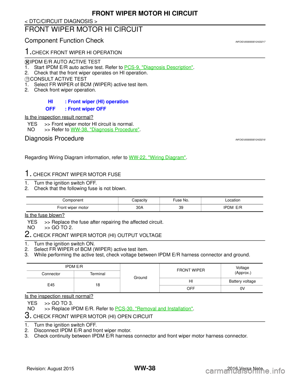
FRONT WIPER MOTOR HI CIRCUIT
FRONT WIPER MOTOR HI CIRCUIT
Component Function CheckINFOID:0000000012433217
1.CHECK FRONT WIPER HI OPERATION
IPDM E/R AUTO ACTIVE TEST
1. Start IPDM E/R auto active test. Refer to PCS-9, "
Diagnosis Description".
2. Check that the front wiper operates on HI operation.
CONSULT ACTIVE TEST
1. Select FR WIPER of BCM (WIPER) active test item.
2. Check front wiper operation.
Is the inspection result normal?
YES >> Front wiper motor HI circuit is normal.
NO >> Refer to WW-38, "
Diagnosis Procedure".
Diagnosis ProcedureINFOID:0000000012433218
Regarding Wiring Diagram information, refer to WW-22, "Wiring Diagram".
1. CHECK FRONT WIPER MOTOR FUSE
1. Turn the ignition switch OFF.
2. Check that the following fuse is not blown.
Is the fuse blown?
YES >> Replace the fuse after repairing the affected circuit.
NO >> GO TO 2.
2. CHECK FRONT WIPER MOTOR (HI) OUTPUT VOLTAGE
1. Turn the ignition switch ON.
2. Select FR WIPER of BCM (WIPER) active test item.
3. While performing the active test, check vo ltage between IPDM E/R harness connector and ground.
Is the inspection result normal?
YES >> GO TO 3.
NO >> Replace IPDM E/R. Refer to PCS-30, "
Removal and Installation".
3. CHECK FRONT WIPER MOTOR (HI) OPEN CIRCUIT
1. Turn the ignition switch OFF.
2. Disconnect IPDM E/R and front wiper motor.
3. Check continuity between IPDM E/R harness connector and front wiper motor harness connector.
HI : Front wiper (HI) operation
OFF : Front wiper OFF
Component CapacityFuse No. Location
Front wiper motor 30A39 IPDM E/R
IPDM E/R
GroundFRONT WIPER
Voltage
(Approx.)
Connector Terminal
E45 18 HI
Battery voltage
OFF 0V
Revision: August 2015 2016 Versa Note
cardiagn.com
Page 3608 of 3641

WASHER MOTOR CIRCUITWW-43
< DTC/CIRCUIT DIAGNOSIS >
C
DE
F
G H
I
J
K
M A
B
WW
N
O P
WASHER MOTOR CIRCUIT
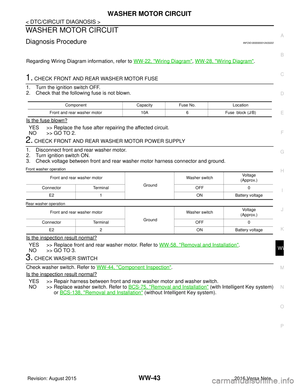
Diagnosis ProcedureINFOID:0000000012433222
Regarding Wiring Diagram information, refer to WW-22, "Wiring Diagram", WW-28, "Wiring Diagram".
1. CHECK FRONT AND REAR WASHER MOTOR FUSE
1. Turn the ignition switch OFF.
2. Check that the following fuse is not blown.
Is the fuse blown?
YES >> Replace the fuse after repairing the affected circuit.
NO >> GO TO 2.
2. CHECK FRONT AND REAR WASHER MOTOR POWER SUPPLY
1. Disconnect front and rear washer motor.
2. Turn ignition switch ON.
3. Check voltage between front and rear washer motor harness connector and ground.
Front washer operation
Rear washer operation
Is the inspection result normal?
YES >> Replace front and rear washer motor. Refer to WW-58, "Removal and Installation".
NO >> GO TO 3.
3. CHECK WASHER SWITCH
Check washer switch. Refer to WW-44, "
Component Inspection".
Is the inspection result normal?
YES >> Repair harness between front and rear washer motor and washer switch.
NO >> Replace washer switch. Refer to BCS-75, "
Removal and Installation" (with Intelligent Key system)
or BCS-138, "
Removal and Installation" (without Intelligent Key system).
Component CapacityFuse No. Location
Front and rear washer motor 10A6Fuse block (J/B)
Front and rear washer motor
GroundWasher switch
Voltage
(Approx.)
Connector Terminal OFF0
E2 1 ONBattery voltage
Front and rear washer motor GroundWasher switch
Voltage
(Approx.)
Connector Terminal OFF0
E2 2 ONBattery voltage
Revision: August 2015 2016 Versa Note
cardiagn.com
Page 3618 of 3641

FRONT WIPER DOES NOT OPERATEWW-53
< SYMPTOM DIAGNOSIS >
C
DE
F
G H
I
J
K
M A
B
WW
N
O P
FRONT WIPER DO ES NOT OPERATE
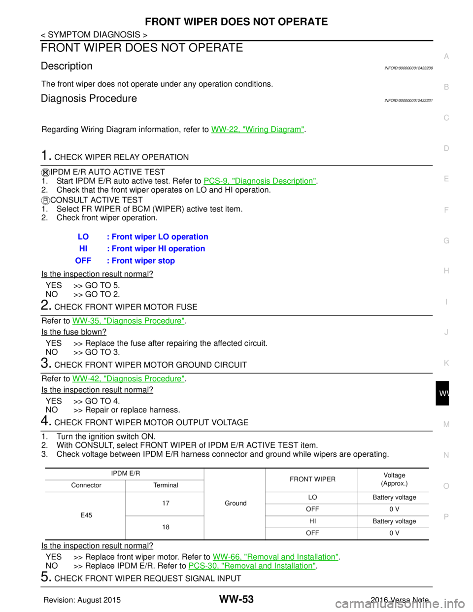
DescriptionINFOID:0000000012433230
The front wiper does not operate under any operation conditions.
Diagnosis ProcedureINFOID:0000000012433231
Regarding Wiring Diagram information, refer to WW-22, "Wiring Diagram".
1. CHECK WIPER RELAY OPERATION
IPDM E/R AUTO ACTIVE TEST
1. Start IPDM E/R auto active test. Refer to PCS-9, "
Diagnosis Description".
2. Check that the front wiper operates on LO and HI operation.
CONSULT ACTIVE TEST
1. Select FR WIPER of BCM (WIPER) active test item.
2. Check front wiper operation.
Is the inspection result normal?
YES >> GO TO 5.
NO >> GO TO 2.
2. CHECK FRONT WIPER MOTOR FUSE
Refer to WW-35, "
Diagnosis Procedure".
Is the fuse blown?
YES >> Replace the fuse after repairing the affected circuit.
NO >> GO TO 3.
3. CHECK FRONT WIPER MOTOR GROUND CIRCUIT
Refer to WW-42, "
Diagnosis Procedure".
Is the inspection result normal?
YES >> GO TO 4.
NO >> Repair or replace harness.
4. CHECK FRONT WIPER MOTOR OUTPUT VOLTAGE
1. Turn the ignition switch ON.
2. With CONSULT, select FRONT WIPER of IPDM E/R ACTIVE TEST item.
3. Check voltage between IPDM E/R harness connector and ground while wipers are operating.
Is the inspection result normal?
YES >> Replace front wiper motor. Refer to WW-66, "Removal and Installation".
NO >> Replace IPDM E/R. Refer to PCS-30, "
Removal and Installation".
5. CHECK FRONT WIPER REQUEST SIGNAL INPUTLO : Front wiper LO operation
HI : Front wiper HI operation
OFF : Front wiper stop
IPDM E/R
GroundFRONT WIPER
Vo l ta g e
(Approx.)
Connector Terminal
E45 17
LO
Battery voltage
OFF 0 V
18 HI
Battery voltage
OFF 0 V
Revision: August 2015 2016 Versa Note
cardiagn.com