2016 NISSAN NOTE fuse diagram
[x] Cancel search: fuse diagramPage 3011 of 3641
![NISSAN NOTE 2016 Service Repair Manual SEC-154
< DTC/CIRCUIT DIAGNOSIS >[WITHOUT INTELLIGENT KEY SYSTEM]
POWER SUPPLY AND GROUND CIRCUIT
POWER SUPPLY AND GROUND CIRCUIT
BCM
BCM : Diagnosis ProcedureINFOID:0000000012542538
Regarding Wiring NISSAN NOTE 2016 Service Repair Manual SEC-154
< DTC/CIRCUIT DIAGNOSIS >[WITHOUT INTELLIGENT KEY SYSTEM]
POWER SUPPLY AND GROUND CIRCUIT
POWER SUPPLY AND GROUND CIRCUIT
BCM
BCM : Diagnosis ProcedureINFOID:0000000012542538
Regarding Wiring](/manual-img/5/57363/w960_57363-3010.png)
SEC-154
< DTC/CIRCUIT DIAGNOSIS >[WITHOUT INTELLIGENT KEY SYSTEM]
POWER SUPPLY AND GROUND CIRCUIT
POWER SUPPLY AND GROUND CIRCUIT
BCM
BCM : Diagnosis ProcedureINFOID:0000000012542538
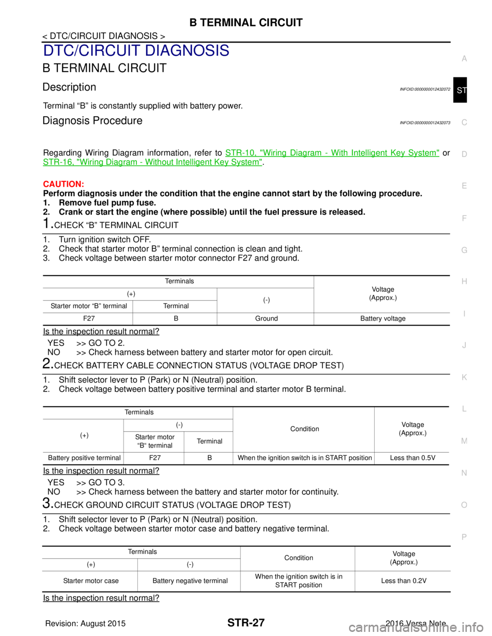
Regarding Wiring Diagram information, refer to
BCS-117, "Wiring Diagram".
1.CHECK FUSES AND FUSIBLE LINK
Check that the following fuses and fusible link are not blown.
Is the fuse blown?
YES >> Replace the blown fuse or fusible link after repairing the affected circuit.
NO >> GO TO 2.
2.CHECK POWER SUPPLY CIRCUIT
1. Turn ignition switch OFF.
2. Disconnect BCM connectors.
3. Check voltage between BCM connector and ground.
Is the inspection result normal?
YES >> GO TO 3.
NO >> Repair harness or connector.
3.CHECK GROUND CIRCUIT
Check continuity between BCM connector and ground.
Is the inspection result normal?
YES >> Inspection End.
NO >> Repair harness or connector.
Terminal No. Signal nameFuses and fusible link No.
37 Battery power supply 8 (10A)
42 12 (10A)
50 G (40A)
11 Ignition switch ACC or ON 18 (10A)
38 Ignition switch ON or START 2 (10A)
BCMGround Ignition switch position
Connector Terminal
—OFF
ACC ON
M18 11
0 V
Battery voltage
Battery voltage
37
Battery voltage
38 0 V0 V
M19 42
Battery voltage Battery voltage
50
BCM GroundContinuity
Connector Terminal
M19 55—Yes
Revision: August 2015 2016 Versa Note
cardiagn.com
Page 3013 of 3641
![NISSAN NOTE 2016 Service Repair Manual SEC-156
< DTC/CIRCUIT DIAGNOSIS >[WITHOUT INTELLIGENT KEY SYSTEM]
VEHICLE SECURITY INDICATOR
4. Check continuity between BCM connector M18 terminal 23 and ground.
Is the inspection result normal?
YES NISSAN NOTE 2016 Service Repair Manual SEC-156
< DTC/CIRCUIT DIAGNOSIS >[WITHOUT INTELLIGENT KEY SYSTEM]
VEHICLE SECURITY INDICATOR
4. Check continuity between BCM connector M18 terminal 23 and ground.
Is the inspection result normal?
YES](/manual-img/5/57363/w960_57363-3012.png)
SEC-156
< DTC/CIRCUIT DIAGNOSIS >[WITHOUT INTELLIGENT KEY SYSTEM]
VEHICLE SECURITY INDICATOR
4. Check continuity between BCM connector M18 terminal 23 and ground.
Is the inspection result normal?
YES >> Check the following:
• 10A fuse No. 8, located in fuse block (J/B)
• Harness for open or short between security indicator lamp and fuse.
NO >> Repair or replace harness.
Diagnosis Procedure (Type A)INFOID:0000000012430489
Regarding Wiring Diagram information, refer to SEC-132, "Wiring Diagram".
1.SECURITY INDICATOR LAMP ACTIVE TEST
With CONSULT
Check “THEFT IND”” in “Active Test” of “IMMU”.
Without CONSULT
1. Disconnect BCM.
2. Check voltage between BCM harness connector M18 terminal 23 and ground.
Is the inspection result normal?
YES >> Security indicator lamp is OK.
NO >> GO TO 2.
2.SECURITY INDICATOR LAMP CHECK
Check security indicator lamp condition.
Is the inspection result normal?
YES >> GO TO 3.
NO >> Replace combination meter. Refer to MWI-54, "
Removal and Installation".
3.CHECK HARNESS CONTINUITY
1. Turn ignition switch OFF.
2. Disconnect BCM and security indicator lamp connector.
3. Check continuity between BCM connector M18 term inal 23 and combination meter connector M82 termi-
nal 18.
4. Check continuity between BCM connector M18 terminal 23 and ground.
BCM Combination meter
Continuity
Connector TerminalConnector Terminal
M 182 3M 241 8 Y es
BCM GroundContinuity
Connector Terminal
M18 23 No
ConnectorTe r m i n a l s
ConditionVoltage (V)
(Approx.)
(+) (-)
M18 23Ground ON
0
OFF Battery voltage
BCM Combination meter
Continuity
Connector TerminalConnector Terminal
M 182 3M 821 8 Y es
Revision: August 2015 2016 Versa Note
cardiagn.com
Page 3179 of 3641

B TERMINAL CIRCUITSTR-27
< DTC/CIRCUIT DIAGNOSIS >
C
DE
F
G H
I
J
K L
M A
STR
NP
O
DTC/CIRCUIT DIAGNOSIS
B TERMINAL CIRCUIT
DescriptionINFOID:0000000012432072
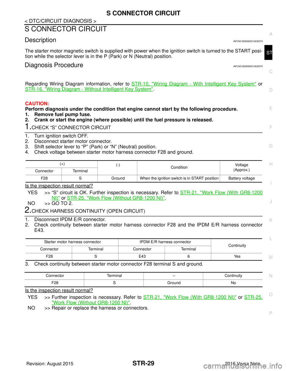
Terminal “B” is constantly supplied with battery power.
Diagnosis ProcedureINFOID:0000000012432073
Regarding Wiring Diagram information, refer to
STR-10, "Wiring Diagram - With Intelligent Key System" or
STR-16, "
Wiring Diagram - Without Intelligent Key System".
CAUTION:
Perform diagnosis under the cond ition that the engine cannot start by the following procedure.
1. Remove fuel pump fuse.
2. Crank or start the engine (where possi ble) until the fuel pressure is released.
1.CHECK “B” TERMINAL CIRCUIT
1. Turn ignition switch OFF.
2. Check that starter motor B” terminal connection is clean and tight.
3. Check voltage between starter motor connector F27 and ground.
Is the inspection result normal?
YES >> GO TO 2.
NO >> Check harness between battery and starter motor for open circuit.
2.CHECK BATTERY CABLE CONNECTION STATUS (VOLTAGE DROP TEST)
1. Shift selector lever to P (P ark) or N (Neutral) position.
2. Check voltage between battery positive terminal and starter motor B terminal.
Is the inspection result normal?
YES >> GO TO 3.
NO >> Check harness between the battery and starter motor for continuity.
3.CHECK GROUND CIRCUIT STATUS (VOLTAGE DROP TEST)
1. Shift selector lever to P (P ark) or N (Neutral) position.
2. Check voltage between starter motor case and battery negative terminal.
Is the inspection result normal?
Te r m i n a l s
Voltage
(Approx.)
(+)
(-)
Starter motor “B” terminal Terminal
F27 BGround Battery voltage
Te r m i n a l s
ConditionVoltage
(Approx.)
(+) (-)
Starter motor “B“ terminal Terminal
Battery positive terminal F27 B When the ignition switch is in START position Less than 0.5V
Te r m i n a l s
ConditionVoltage
(Approx.)
(+) (-)
Starter motor case Battery negative terminal When the ignition switch is in
START position Less than 0.2V
Revision: August 2015
2016 Versa Note
cardiagn.com
Page 3181 of 3641

S CONNECTOR CIRCUITSTR-29
< DTC/CIRCUIT DIAGNOSIS >
C
DE
F
G H
I
J
K L
M A
STR
NP
O
S CONNECTOR CIRCUIT
DescriptionINFOID:0000000012432074
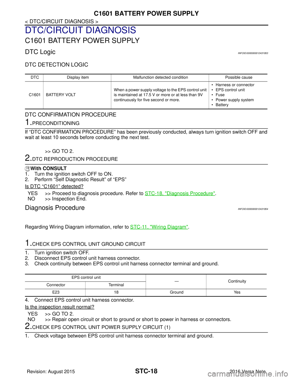
The starter motor magnetic switch is supplied with power when the ignition switch is turned to the START posi-
tion while the selector lever is in the P (Park) or N (Neutral) position.
Diagnosis ProcedureINFOID:0000000012432075
Regarding Wiring Diagram information, refer to
STR-10, "Wiring Diagram - With Intelligent Key System" or
STR-16, "
Wiring Diagram - Without Intelligent Key System".
CAUTION:
Perform diagnosis under the cond ition that engine cannot start by the following procedure.
1. Remove fuel pump fuse.
2. Crank or start the engine (where possi ble) until the fuel pressure is released.
1.CHECK “S” CONNECTOR CIRCUIT
1. Turn ignition switch OFF.
2. Disconnect starter motor connector.
3. Shift selector lever to “P” (Park) or “N” (Neutral) position.
4. Check voltage between starter motor harness connector F28 and ground.
Is the inspection result normal?
YES >> “S” circuit is OK. Further inspection is necessary. Refer to STR-21, "Work Flow (With GR8-1200
NI)" or STR-25, "Work Flow (Without GR8-1200 NI)".
NO >> GO TO 2.
2.CHECK HARNESS CONTINUI TY (OPEN CIRCUIT)
1. Disconnect IPDM E/R connector.
2. Check continuity between starter motor harnes s connector F28 and the IPDM E/R harness connector
E43.
3. Check continuity between starter motor connector F28 terminal S and ground.
Is the inspection result normal?
YES >> Further inspection is necessary. Refer to STR-21, "Work Flow (With GR8-1200 NI)" or STR-25,
"Work Flow (Without GR8-1200 NI)".
NO >> Repair or replace the harness or connectors.
(+) (-)
Condition Voltage
(Approx.)
Connector Terminal
F28 SGround When the ignition switch is in START position Battery voltage
Starter motor harness connector IPDM E/R harness connector
Continuity
Connector TerminalConnector Terminal
F28 SE43 6Yes
Connector Terminal –Continuity
F28 SGround No
Revision: August 2015 2016 Versa Note
cardiagn.com
Page 3202 of 3641

STC-18
< DTC/CIRCUIT DIAGNOSIS >
C1601 BATTERY POWER SUPPLY
DTC/CIRCUIT DIAGNOSIS
C1601 BATTERY POWER SUPPLY
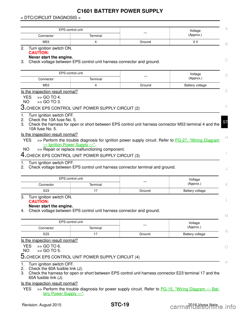
DTC LogicINFOID:0000000012431953
DTC DETECTION LOGIC
DTC CONFIRMATION PROCEDURE
1.PRECONDITIONING
If “DTC CONFIRMATION PROCEDURE” has been previously conducted, always turn ignition switch OFF and
wait at least 10 seconds before conducting the next test.
>> GO TO 2.
2.DTC REPRODUCTION PROCEDURE
With CONSULT
1. Turn the ignition switch OFF to ON.
2. Perform “Self Diagnostic Result” of “EPS”
Is DTC
“C1601” detected?
YES >> Proceed to diagnosis procedure. Refer to STC-18, "Diagnosis Procedure".
NO >> Inspection End.
Diagnosis ProcedureINFOID:0000000012431954
Regarding Wiring Diagram information, refer to STC-11, "Wiring Diagram".
1.CHECK EPS CONTROL UNIT GROUND CIRCUIT
1. Turn ignition switch OFF.
2. Disconnect EPS control unit harness connector.
3. Check continuity between EPS contro l unit harness connector terminal and ground.
4. Connect EPS control unit harness connector.
Is the inspection result normal?
YES >> GO TO 2.
NO >> Repair open circuit or short to ground or short to power in harness or connectors.
2.CHECK EPS CONTROL UNIT PO WER SUPPLY CIRCUIT (1)
1. Check voltage between EPS control unit harness connector terminal and ground.
DTC Display item Malfunction detected condition Possible cause
C1601 BATTERY VOLT When a power supply voltage to the EPS control unit
is maintained at 17.5 V or more or at less than 9V
continuously for five second or more. • Harness or connector
• EPS control unit
•Fuse
• Power supply system
•Battery
EPS control unit
—Con tin uit y
Connector Terminal
E23 18Ground Yes
Revision: August 2015 2016 Versa Note
cardiagn.com
Page 3203 of 3641

C1601 BATTERY POWER SUPPLYSTC-19
< DTC/CIRCUIT DIAGNOSIS >
C
DE
F
H I
J
K L
M A
B
STC
N
O P
2. Turn ignition switch ON. CAUTION:
Never start the engine.
3. Check voltage between EPS control unit harness connector and ground.
Is the inspection result normal?
YES >> GO TO 4.
NO >> GO TO 3.
3.CHECK EPS CONTROL UNIT POWER SUPPLY CIRCUIT (2)
1. Turn ignition switch OFF.
2. Check the 10A fuse No. 5.
3. Check the harness for open or short between EPS c ontrol unit harness connector M53 terminal 4 and the
10A fuse No. 5.
Is the inspection result normal?
YES >> Perform the trouble diagnosis for i gnition power supply circuit. Refer to PG-27, "Wiring Diagram
— Ignition Power Supply —".
NO >> Repair or replace malfunctioning component.
4.CHECK EPS CONTROL UNIT POWER SUPPLY CIRCUIT (3)
1. Turn ignition switch OFF.
2. Check voltage between EPS control unit harness connector terminal and ground.
3. Turn ignition switch ON. CAUTION:
Never start the engine.
4. Check voltage between EPS control unit harness connector and ground.
Is the inspection result normal?
YES >> GO TO 6.
NO >> GO TO 5.
5.CHECK EPS CONTROL UNIT POWER SUPPLY CIRCUIT (4)
1. Turn ignition switch OFF.
2. Check the 60A fusible link (J).
3. Check the harness for open or short between EPS c ontrol unit harness connector E23 terminal 17 and the
60A fusible link (J).
Is the inspection result normal?
YES >> Perform the trouble diagnosis fo r power supply circuit. Refer to PG-15, "Wiring Diagram — Bat-
tery Power Supply —".
EPS control unit
—Vol tag e
(Approx.)
Connector Terminal
M53 4Ground 0 V
EPS control unit
—Voltage
(Approx.)
Connector Terminal
M53 4GroundBattery voltage
EPS control unit
—Vo l ta g e
(Approx.)
Connector Terminal
E23 17GroundBattery voltage
EPS control unit —Vol tag e
(Approx.)
Connector Terminal
E23 17GroundBattery voltage
Revision: August 2015 2016 Versa Note
cardiagn.com
Page 3549 of 3641

WCS-34
< DTC/CIRCUIT DIAGNOSIS >
POWER SUPPLY AND GROUND CIRCUIT
DTC/CIRCUIT DIAGNOSIS
POWER SUPPLY AND GROUND CIRCUIT
COMBINATION METER (TYPE A)
COMBINATION METER (TYPE A) : Diagnosis ProcedureINFOID:0000000012542990
Regarding Wiring Diagram information, refer to MWI-26, "Wiring Diagram".
1.CHECK FUSE
Check that the following fuses are not blown.
Is the fuse blown?
YES >> Replace the blown fuse after repairing the affected circuit.
NO >> GO TO 2.
2.POWER SUPPLY CIRCUIT CHECK
1. Disconnect combination meter connector.
2. Check voltage between combination meter harness connector M82, terminals 27, 28, 15 and ground.
Is the inspection result normal?
YES >> GO TO 3.
NO >> Repair or replace harness or connector.
3.GROUND CIRCUIT CHECK
1. Turn ignition switch OFF.
2. Disconnect combination meter connector.
3. Check continuity between combination meter har ness connector M82, terminals 21, 22, 23 and ground.
Is the inspection result normal?
YES >> Inspection End.
NO >> Repair or replace harness or connector.
COMBINATION METER (TYPE B)
Power source Fuse No.
Battery 8
Ignition switch ON or START 3
Ignition switch ACC or ON 18
TerminalsIgnition switch position
(+) (–)OFF ACC ONSTART
Connector Terminal
M82 27
GroundBattery voltage Battery voltage Battery voltage Battery voltage
28 0V0VBattery voltage Battery voltage
15 0V Battery voltage Battery voltage 0V
Te r m i n a l s
Continuity
(+)
(–)
Connector Terminal
M82 21
Ground Yes
22
23
Revision: August 2015 2016 Versa Note
cardiagn.com
Page 3550 of 3641

WCS
POWER SUPPLY AND GROUND CIRCUITWCS-35
< DTC/CIRCUIT DIAGNOSIS >
C
DE
F
G H
I
J
K L
M B A
O P
COMBINATION METER (TYPE B) : Diagnosis ProcedureINFOID:0000000012542991
Regarding Wiring Diagram information, refer to MWI-79, "Wiring Diagram".
1.CHECK FUSE
Check that the following fuses are not blown.
Is the fuse blown?
YES >> Replace the blown fuse after repairing the affected circuit.
NO >> GO TO 2.
2.POWER SUPPLY CIRCUIT CHECK
1. Disconnect combination meter connector.
2. Check voltage between combination meter harness connector M24, terminals 27, 28, 15 and ground.
Is the inspection result normal?
YES >> GO TO 3.
NO >> Repair or replace harness or connector.
3.GROUND CIRCUIT CHECK
1. Turn ignition switch OFF.
2. Disconnect combination meter connector.
3. Check continuity between combination meter harness connector M24, terminals 21, 22, 23 and ground.
Is the inspection result normal?
YES >> Inspection End.
NO >> Repair or replace harness or connector.
BCM (BODY CONTROL SYSTEM) (W ITH INTELLIGENT KEY SYSTEM)
BCM (BODY CONTROL SYSTEM) (WITH IN TELLIGENT KEY SYSTEM) : Diagnosis
Procedure
INFOID:0000000012542992
Regarding Wiring Diagram information, refer to BCS-52, "Wiring Diagram".
Power source Fuse No.
Battery 8
Ignition switch ON or START 3
Ignition switch ACC or ON 18
TerminalsIgnition switch position
(+) (–)OFF ACC ONSTART
Connector Terminal
M24 27
GroundBattery voltage Battery voltage Battery voltage Battery voltage
28 0V0VBattery voltage Battery voltage
15 0V Battery voltage Battery voltage 0V
Te r m i n a l s
Continuity
(+)
(–)
Connector Terminal
M24 21
Ground Yes
22
23
Revision: August 2015 2016 Versa Note
cardiagn.com