2016 NISSAN NOTE fuse diagram
[x] Cancel search: fuse diagramPage 1729 of 3641

HEADLAMP (HI) CIRCUITEXL-77
< DTC/CIRCUIT DIAGNOSIS >
C
DE
F
G H
I
J
K
M A
B
EXL
N
O P
HEADLAMP (HI) CIRCUIT
DescriptionINFOID:0000000012432804
The IPDM E/R (intelligent power distribution modul e engine room) controls the headlamp high relay based on
inputs from the BCM via the CAN communication lines. When the headlamp high relay is energized, power
flows through fuses 34 and 35, located in the IPDM E/R. Power then flows to the front combination lamp LH
and RH high beams.
Component Function CheckINFOID:0000000012432805
1.CHECK HEADLAMP (HI) OPERATION
WITHOUT CONSULT
1. Start IPDM E/R auto active test. Refer to PCS-9, "
Diagnosis Description".
2. Check that the headlamp switches to the high beam.
CONSULT
1. Select EXTERNAL LAMPS of IP DM E/R active test item.
2. While operating the test items, check that the headlamp switches to the high beam.
Does the headlamp switch to high beam?
YES >> Headlamp (HI) circuit is normal.
NO >> Refer to EXL-77, "
Diagnosis Procedure".
Diagnosis ProcedureINFOID:0000000012432806
Regarding Wiring Diagram information, refer to EXL-25, "Wiring Diagram - For USA" or EXL-31, "Wiring Dia-
gram - For Canada".
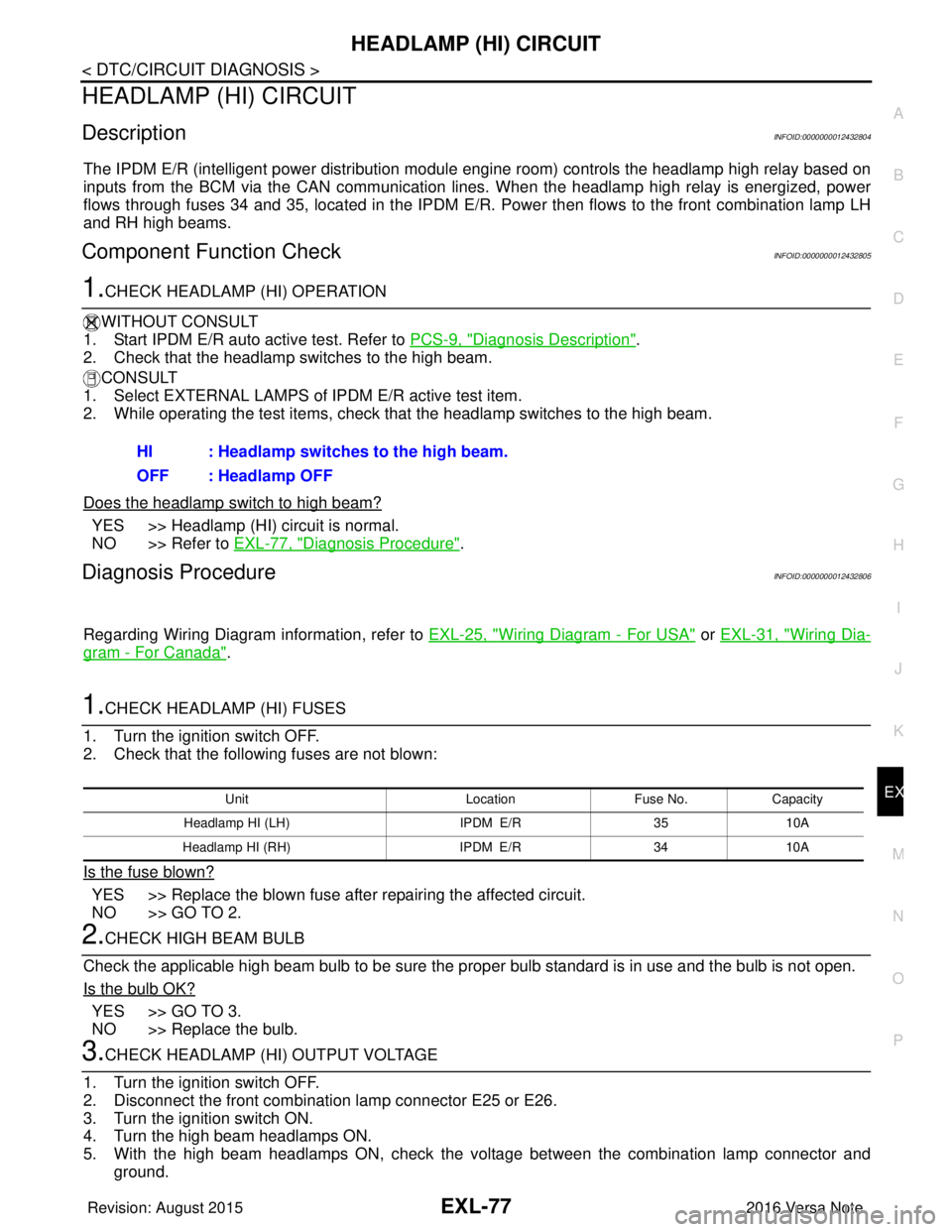
1.CHECK HEADLAMP (HI) FUSES
1. Turn the ignition switch OFF.
2. Check that the following fuses are not blown:
Is the fuse blown?
YES >> Replace the blown fuse after repairing the affected circuit.
NO >> GO TO 2.
2.CHECK HIGH BEAM BULB
Check the applicable high beam bulb to be sure the proper bulb standard is in use and the bulb is not open.
Is the bulb OK?
YES >> GO TO 3.
NO >> Replace the bulb.
3.CHECK HEADLAMP (HI) OUTPUT VOLTAGE
1. Turn the ignition switch OFF.
2. Disconnect the front combination lamp connector E25 or E26.
3. Turn the ignition switch ON.
4. Turn the high beam headlamps ON.
5. With the high beam headlamps ON, check the vo ltage between the combination lamp connector and
ground. HI : Headlamp switches to the high beam.
OFF : Headlamp OFF
Unit
LocationFuse No.Capacity
Headlamp HI (LH) IPDM E/R3510A
Headlamp HI (RH) IPDM E/R3410A
Revision: August 2015 2016 Versa Note
cardiagn.com
Page 1731 of 3641

HEADLAMP (LO) CIRCUITEXL-79
< DTC/CIRCUIT DIAGNOSIS >
C
DE
F
G H
I
J
K
M A
B
EXL
N
O P
HEADLAMP (LO) CIRCUIT
DescriptionINFOID:0000000012432807
The IPDM E/R (intelligent power distribution modul e engine room) controls the headlamp low relay based on
inputs from the BCM via the CAN communication li nes. When the headlamp low relay is energized, power
flows through fuses 40 and 41, located in the IPDM E/R.
(Without daytime running light system) power then flow s to the front combination lamp LH and RH low beams.
(With daytime running light system) power then flows to the front combination lamp LH low beam and the day-
time running light relay 2 which becomes energized and t hen power is sent to the front combination lamp RH
low beam.
Component Function CheckINFOID:0000000012432808
1.CHECK HEADLAMP (LO) OPERATION
WITHOUT CONSULT
1. Start IPDM E/R auto active test. Refer to PCS-9, "
Diagnosis Description".
2. Check that the headlamp is turned ON.
CONSULT
1. Select EXTERNAL LAMPS of IP DM E/R active test item.
2. While operating the test items, check that the headlamp is turned ON.
Is the headlamp turned ON?
YES >> Headlamp (LO) is normal.
NO >> Refer to EXL-79, "
Diagnosis Procedure".
Diagnosis ProcedureINFOID:0000000012432809
Regarding Wiring Diagram information, refer to EXL-25, "Wiring Diagram - For USA" or EXL-31, "Wiring Dia-
gram - For Canada".
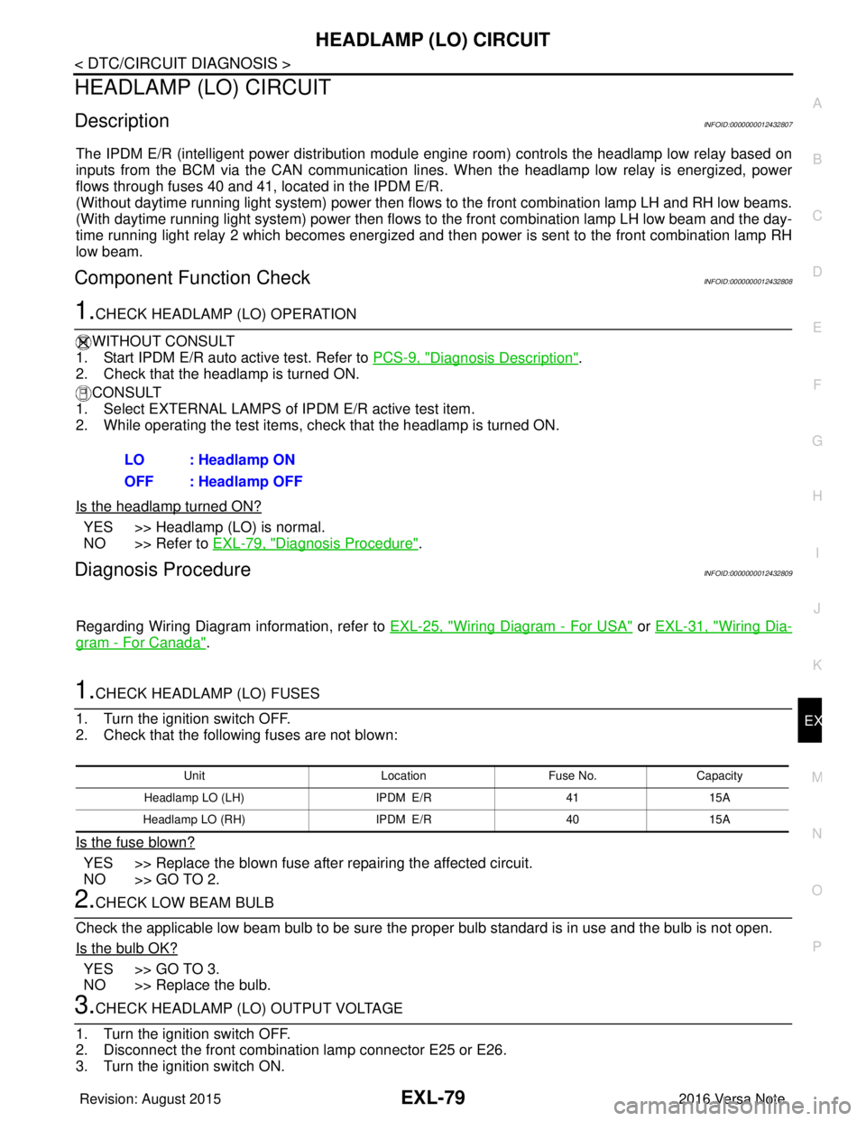
1.CHECK HEADLAMP (LO) FUSES
1. Turn the ignition switch OFF.
2. Check that the following fuses are not blown:
Is the fuse blown?
YES >> Replace the blown fuse after repairing the affected circuit.
NO >> GO TO 2.
2.CHECK LOW BEAM BULB
Check the applicable low beam bulb to be sure the proper bulb standard is in use and the bulb is not open.
Is the bulb OK?
YES >> GO TO 3.
NO >> Replace the bulb.
3.CHECK HEADLAMP (LO) OUTPUT VOLTAGE
1. Turn the ignition switch OFF.
2. Disconnect the front combination lamp connector E25 or E26.
3. Turn the ignition switch ON. LO : Headlamp ON
OFF : Headlamp OFF
Unit
LocationFuse No.Capacity
Headlamp LO (L H) IPDM E/R 4115A
Headlamp LO (RH) IPDM E/R4015A
Revision: August 2015 2016 Versa Note
cardiagn.com
Page 1734 of 3641

EXL-82
< DTC/CIRCUIT DIAGNOSIS >
PARKING LAMP CIRCUIT
PARKING LAMP CIRCUIT
DescriptionINFOID:0000000012432810
The IPDM E/R (intelligent power distribution module engine room) controls the tail lamp relay based on inputs
from the BCM via the CAN communication lines. When the tail lamp relay is energized, power flows through
fuse 37, located in the IPDM E/R. Power then flows through the tail lamp relay to the front and rear combina-
tion lamps, license plate lamps.
Component Function CheckINFOID:0000000012432811
1.CHECK PARKING LAMP OPERATION
WITHOUT CONSULT
1. Start IPDM E/R auto active test. Refer to PCS-9, "
Diagnosis Description".
2. Check that the parking lamps are turned ON.
CONSULT
1. Select EXTERNAL LAMPS of IPDM E/R active test item.
2. While operating the test items, check that the parking lamps are turned ON.
Is the parking lamp turned ON?
YES >> Parking lamp circuit is normal.
NO >> Refer to EXL-82, "
Diagnosis Procedure".
Diagnosis ProcedureINFOID:0000000012432812
Regarding Wiring Diagram information, refer to EXL-55, "Wiring Diagram".
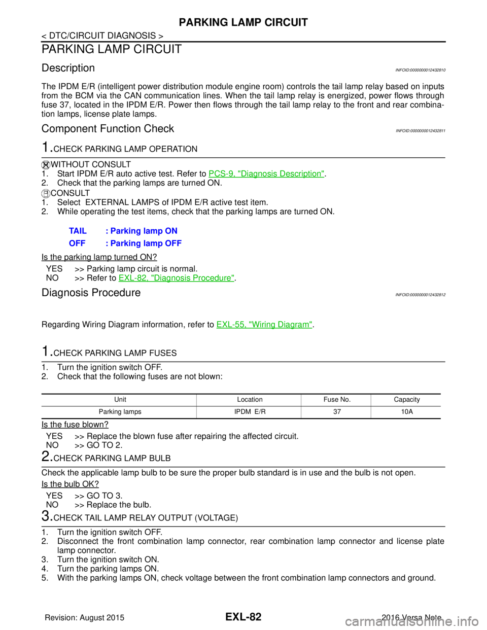
1.CHECK PARKING LAMP FUSES
1. Turn the ignition switch OFF.
2. Check that the following fuses are not blown:
Is the fuse blown?
YES >> Replace the blown fuse after repairing the affected circuit.
NO >> GO TO 2.
2.CHECK PARKING LAMP BULB
Check the applicable lamp bulb to be sure the proper bulb standard is in use and the bulb is not open.
Is the bulb OK?
YES >> GO TO 3.
NO >> Replace the bulb.
3.CHECK TAIL LAMP RELAY OUTPUT (VOLTAGE)
1. Turn the ignition switch OFF.
2. Disconnect the front combination lamp connector, rear combination lamp connector and license plate
lamp connector.
3. Turn the ignition switch ON.
4. Turn the parking lamps ON.
5. With the parking lamps ON, check voltage between the front combination lamp connectors and ground. TAIL : Parking lamp ON
OFF : Parking lamp OFF
Unit
LocationFuse No.Capacity
Parking lamps IPDM E/R3710A
Revision: August 2015 2016 Versa Note
cardiagn.com
Page 1740 of 3641

EXL-88
< DTC/CIRCUIT DIAGNOSIS >
FRONT FOG LAMP CIRCUIT
FRONT FOG LAMP CIRCUIT
Component Function CheckINFOID:0000000012432816
1.CHECK FRONT FOG LAMP OPERATION
WITHOUT CONSULT
1. Start IPDM E/R auto active test. Refer to PCS-9, "
Diagnosis Description".
2. Check that the front fog lamp is turned ON.
CONSULT
1. Select EXTERNAL LAMPS of IPDM E/R active test item.
2. While operating the test items, check that the front fog lamp is turned ON.
Is the front fog lamp turned ON?
YES >> Front fog lamp circuit is normal.
NO >> Refer to EXL-88, "
Diagnosis Procedure".
Diagnosis ProcedureINFOID:0000000012432817
Regarding Wiring Diagram information, refer to EXL-43, "Wiring Diagram".
1.CHECK FRONT FOG LAMP FUSE
1. Turn ignition switch OFF.
2. Check that the following fuse is not blown:
Is the fuse blown?
YES >> GO TO 2.
NO >> Replace the blown fuse after repairing the affected circuit.
2.CHECK FOG LAMP BULB
Check the applicable fog lamp bulb to be sure the proper bulb standard is in use and the bulb is not open.
Is the bulb OK?
YES >> GO TO 3.
NO >> Replace the bulb.
3.CHECK FRONT FOG LAMP OUTPUT VOLTAGE
CONSULT ACTIVE TEST
1. Turn ignition switch OFF.
2. Disconnect front fog lamp connector.
3. Turn ignition switch ON.
4. Select EXTERNAL LAMPS of IPDM E/R active test item.
5. While operating the fog lamps, check voltage between front fog lamp harness connector and ground.
FOG : Front fog lamp ON
OFF : Front fog lamp OFF
Unit
Fuse No.Capacity
Front fog lamp 3115 A
(+)
(−) Test item Vo l ta g e
(Approx.)
Front fog lamp
Connector Terminal
Revision: August 2015 2016 Versa Note
cardiagn.com
Page 1898 of 3641

GI-10
< HOW TO USE THIS MANUAL >
HOW TO READ WIRING DIAGRAMS
Sample/Wiring Diagram -Example-
INFOID:0000000012433152
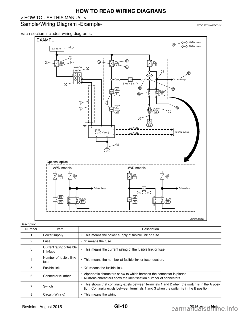
Each section includes wiring diagrams.
Description
JCAWA0150GB
Number Item Description
1 Power supply • This means the power supply of fusible link or fuse.
2 Fuse • “/” means the fuse.
3 Current rating of fusible
link/fuse • This means the current rating of the fusible link or fuse.
4 Number of fusible link/
fuse
• This means the number of fusible link or fuse location.
5 Fusible link • “X” means the fusible link.
6 Connector number • Alphabetic characters show to which harness the connector is placed.
• Numeric characters show the identification number of connectors.
7Switch • This shows that continuity exists between terminals 1 and 2 when the switch is in the A posi-
tion. Continuity exists between terminals 1 and 3 when the switch is in the B position.
8 Circuit (Wiring) • This means the wiring.
Revision: August 2015 2016 Versa Note
cardiagn.com
Page 2000 of 3641
![NISSAN NOTE 2016 Service Repair Manual HAC-32
< DTC/CIRCUIT DIAGNOSIS >[MANUAL AIR CONDITIONING]
A/C ON SIGNAL
DTC/CIRCUIT DIAGNOSIS
A/C ON SIGNAL
Component Function CheckINFOID:0000000012430729
1.CHECK A/C ON SIGNAL
With CONSULT
1. Turn i NISSAN NOTE 2016 Service Repair Manual HAC-32
< DTC/CIRCUIT DIAGNOSIS >[MANUAL AIR CONDITIONING]
A/C ON SIGNAL
DTC/CIRCUIT DIAGNOSIS
A/C ON SIGNAL
Component Function CheckINFOID:0000000012430729
1.CHECK A/C ON SIGNAL
With CONSULT
1. Turn i](/manual-img/5/57363/w960_57363-1999.png)
HAC-32
< DTC/CIRCUIT DIAGNOSIS >[MANUAL AIR CONDITIONING]
A/C ON SIGNAL
DTC/CIRCUIT DIAGNOSIS
A/C ON SIGNAL
Component Function CheckINFOID:0000000012430729
1.CHECK A/C ON SIGNAL
With CONSULT
1. Turn ignition switch ON.
2. Operate front blower motor.
3. Select “AIR CONDITIONER” of “BCM”.
4. Select “AIR COND SW” in “Data Monitor”, and check status under the following condition.
Is the inspection result normal?
YES >> Inspection End.
NO >> Refer to HAC-32, "
Diagnosis Procedure".
Diagnosis ProcedureINFOID:0000000012545183
Regarding Wiring Diagram information, refer to HAC-22, "Wiring Diagram".
1.CHECK FUSE
1. Turn ignition switch OFF.
2. Check 10A fuse (No. 21, located in fuse block (J/B)]. NOTE:
Refer to PG-58, "
Terminal Arrangement".
Is the inspection result normal?
YES >> GO TO 2.
NO >> Replace the blown fuse after repairing the affected circuit.
2.CHECK THERMO CONTROL AMP. POWER SUPPLY
1. Turn ignition switch OFF.
2. Disconnect thermo control amp. connector.
3. Turn ignition switch ON.
4. Check voltage between thermo control amp. harness connector and ground.
Is the inspection result normal?
YES >> GO TO 3.
NO >> Repair harness or connector between thermo control amp. and fuse.
3.CHECK THERMO CONTROL AM P. GROUND CIRCUIT FOR OPEN
1. Turn ignition switch OFF.
2. Check continuity between thermo c ontrol amp. harness connector and ground.
Monitor item Condition Status
AIR COND SW A/C switch ON
On
OFF Off
+
−Voltage (V)
(Approx.)
Thermo control amp.
Connector Terminal
M42 3GroundBattery voltage
Revision: August 2015 2016 Versa Note
cardiagn.com
Page 2007 of 3641
![NISSAN NOTE 2016 Service Repair Manual A/C INDICATORHAC-39
< DTC/CIRCUIT DIAGNOSIS > [MANUAL AIR CONDITIONING]
C
D
E
F
G H
J
K L
M A
B
HAC
N
O P
A/C INDICATOR
Diagnosis ProcedureINFOID:0000000012430739
Regarding Wiring Diagram information, NISSAN NOTE 2016 Service Repair Manual A/C INDICATORHAC-39
< DTC/CIRCUIT DIAGNOSIS > [MANUAL AIR CONDITIONING]
C
D
E
F
G H
J
K L
M A
B
HAC
N
O P
A/C INDICATOR
Diagnosis ProcedureINFOID:0000000012430739
Regarding Wiring Diagram information,](/manual-img/5/57363/w960_57363-2006.png)
A/C INDICATORHAC-39
< DTC/CIRCUIT DIAGNOSIS > [MANUAL AIR CONDITIONING]
C
D
E
F
G H
J
K L
M A
B
HAC
N
O P
A/C INDICATOR
Diagnosis ProcedureINFOID:0000000012430739
Regarding Wiring Diagram information, refer to HAC-22, "Wiring Diagram".
1.CHECK SYMPTOM
Check symptom (A or B).
Which symptom is detected?
A >> GO TO 2.
B >> GO TO 6.
2.CHECK FUSE
1. Turn ignition switch OFF.
2. Check 10A fuse (No. 21, located in fuse block (J/B)]. NOTE:
Refer to PG-58, "
Terminal Arrangement".
Is the inspection result normal?
YES >> GO TO 3.
NO >> Replace the blown fuse after repairing the affected circuit.
3.CHECK A/C INDICATOR POWER SUPPLY
1. Turn ignition switch ON.
2. Check voltage between front air control harness connector and ground.
Is the inspection result normal?
YES >> GO TO 4.
NO >> Repair harness or connector between front air control and fuse.
4.CHECK A/C INDICATOR CIRCUIT
Check voltage between front air control harness connector and ground.
Is the inspection result normal?
YES >> GO TO 5.
NO >> Replace front air control. Refer to HAC-52, "
Removal and Installation".
5.CHECK A/C INDICATOR CIRCUIT FOR OPEN
1. Turn ignition switch OFF.
2. Disconnect front air control connector and BCM connector.
3. Check continuity between front air control harness connector and BCM harness connector.
Symptom
A A/C indicator does not turn ON.
B A/C indicator does not turn OFF.
+ −Vo l ta g e
(Approx.)
Front air control
Connector Terminal
M33 15 GroundBattery voltage
+
−Vo l ta g e
(Approx.)
Front air control
Connector Terminal
M33 14 GroundBattery voltage
Revision: August 2015 2016 Versa Note
cardiagn.com
Page 2009 of 3641
![NISSAN NOTE 2016 Service Repair Manual FRONT BLOWER MOTORHAC-41
< DTC/CIRCUIT DIAGNOSIS > [MANUAL AIR CONDITIONING]
C
D
E
F
G H
J
K L
M A
B
HAC
N
O P
FRONT BLOWER MOTOR
DescriptionINFOID:0000000012430740
The front blower motor utilizes a b NISSAN NOTE 2016 Service Repair Manual FRONT BLOWER MOTORHAC-41
< DTC/CIRCUIT DIAGNOSIS > [MANUAL AIR CONDITIONING]
C
D
E
F
G H
J
K L
M A
B
HAC
N
O P
FRONT BLOWER MOTOR
DescriptionINFOID:0000000012430740
The front blower motor utilizes a b](/manual-img/5/57363/w960_57363-2008.png)
FRONT BLOWER MOTORHAC-41
< DTC/CIRCUIT DIAGNOSIS > [MANUAL AIR CONDITIONING]
C
D
E
F
G H
J
K L
M A
B
HAC
N
O P
FRONT BLOWER MOTOR
DescriptionINFOID:0000000012430740
The front blower motor utilizes a brush-less motor with a rotating magnet. Quietness is improved over previous
motors where the brush was the poi nt of contact and the coil rotated.
Diagnosis ProcedureINFOID:0000000012430741
Regarding Wiring Diagram information, refer to HAC-22, "Wiring Diagram".
1.CHECK SYMPTOM
Check symptom (A or B).
Which symptom is detected?
A >> GO TO 2.
B >> GO TO 7.
2.CHECK FUSE
1. Turn ignition switch OFF.
2. Check 15A fuses (Nos. 20 and 22, located in fuse block (J/B)]. NOTE:
Refer to PG-58, "
Terminal Arrangement".
Is the inspection result normal?
YES >> GO TO 3.
NO >> Replace the blown fuse after repairing the affected circuit.
3.CHECK FRONT BLOWER MOTOR POWER SUPPLY
1. Disconnect front blower motor connector.
2. Turn ignition switch ON.
3. Check voltage between front blower motor harness connector and ground.
Is the inspection result normal?
YES >> GO TO 5.
NO >> GO TO 4.
4.CHECK BLOWER RELAY
1. Turn ignition switch OFF.
2. Check blower relay. Refer to HAC-43, "
Component Inspection (Blower Relay)".
Is the inspection result normal?
YES >> Repair harness or connector between front blower motor and fuse.
NO >> Replace blower relay.
5.CHECK FAN SWITCH GROUND CIRCUIT FOR OPEN
1. Turn ignition switch OFF.
2. Disconnect front air control connector.
Symptom
A Front blower motor does not operate at any dial position.
B Front blower motor does not operate at any dial position other than 4th, or operation speed is not normal.
+ −Voltage (V)
(Approx.)
Front blower motor
Connector Terminal
M62 1 GroundBattery voltage
Revision: August 2015 2016 Versa Note
cardiagn.com