2016 NISSAN NOTE engine
[x] Cancel search: enginePage 1643 of 3641
![NISSAN NOTE 2016 Service Repair Manual OIL COOLERLU-13
< REMOVAL AND INSTALLATION > [HR16DE]
C
D
E
F
G H
I
J
K L
M A
LU
NP
O
OIL COOLER
Exploded ViewINFOID:0000000012432206
Removal and InstallationINFOID:0000000012432207
REMOVAL
WARNING:
D NISSAN NOTE 2016 Service Repair Manual OIL COOLERLU-13
< REMOVAL AND INSTALLATION > [HR16DE]
C
D
E
F
G H
I
J
K L
M A
LU
NP
O
OIL COOLER
Exploded ViewINFOID:0000000012432206
Removal and InstallationINFOID:0000000012432207
REMOVAL
WARNING:
D](/manual-img/5/57363/w960_57363-1642.png)
OIL COOLERLU-13
< REMOVAL AND INSTALLATION > [HR16DE]
C
D
E
F
G H
I
J
K L
M A
LU
NP
O
OIL COOLER
Exploded ViewINFOID:0000000012432206
Removal and InstallationINFOID:0000000012432207
REMOVAL
WARNING:
Do not remove the radiator cap when the engine is
hot. Serious burns could occur from high-pressure
engine coolant escaping from the radi ator. Wrap a thick cloth around the radiator cap. Slowly turn it a
quarter of a turn to release built-up pressure. Carefu lly remove radiator cap by turning it all the way.
NOTE:
When removing components such as hoses, tubes/lines, etc. , cap or plug openings to prevent fluid from spill-
ing.
1. Drain engine oil. Refer to LU-8, "
Draining".
2. Drain engine coolant. Refer to CO-8, "
Draining Engine Coolant".
3. Remove oil filter. Refer to LU-10, "
Removal and Installation".
4. Remove water hoses from the oil cooler.
5. Remove oil cooler and O-ring. CAUTION:
Do not reuse O-rings.
1. Radiator hose (upper) 2. Hose clamp3. Water hose
4. Radiator hose (lower) 5. Connector bolt6. Oil cooler
7. O-ring 8. Relief valve9. Water hose
A. To radiator (upper side) B. To radiator (lower side)
AWBIA1596ZZ
Revision: August 2015 2016 Versa Note
cardiagn.com
Page 1644 of 3641
![NISSAN NOTE 2016 Service Repair Manual LU-14
< REMOVAL AND INSTALLATION >[HR16DE]
OIL COOLER
INSPECTION AFTER REMOVAL
Oil Cooler
Check oil cooler for cracks. Check oil cooler for clogging by blowing compressed air through engine coolant
in NISSAN NOTE 2016 Service Repair Manual LU-14
< REMOVAL AND INSTALLATION >[HR16DE]
OIL COOLER
INSPECTION AFTER REMOVAL
Oil Cooler
Check oil cooler for cracks. Check oil cooler for clogging by blowing compressed air through engine coolant
in](/manual-img/5/57363/w960_57363-1643.png)
LU-14
< REMOVAL AND INSTALLATION >[HR16DE]
OIL COOLER
INSPECTION AFTER REMOVAL
Oil Cooler
Check oil cooler for cracks. Check oil cooler for clogging by blowing compressed air through engine coolant
inlet. If necessary, replace oil cooler.
Relief Valve
Inspect relief valve for movement, cracks and breaks by
pushing the ball. If replacement is necessary, remove
the valve by prying it out using a suitable tool. Install a new valve by tapping it in place.
INSTALLATION
Installation is in the reverse order of removal.
• Ensure that no foreign objects are adhering to the s ealing surfaces of the oil cooler and oil pan (upper).
• Tighten connector bolt after aligning cutout (1) on oil cooler with protrusion (2) on oil pan (upper) side.
CAUTION:
• Do not reuse O-ring.
• Replace relief valve if removed.
INSPECTION AFTER INSTALLATION
• Before starting engine, check oil/fluid levels, including engine coolant and engine oil. If less than required
quantity, fill to the specified level. Refer to MA-11, "
Fluids and Lubricants".
• Use procedure below to check for fuel leaks.
• Turn ignition switch ON (with engine stopped). With fuel pressure applied to fuel piping, check for fuel leaks
at connection points.
• Start engine. With engine speed increased, che ck again for fuel leaks at connection points.
• Run engine to check for unusual noise and vibration. NOTE:
If hydraulic pressure inside timing chain tensioner drops after removal and installation, slack in the guide
may generate a pounding noise during and just after engine start. However, this is normal. Noise will stop
after hydraulic pressure rises.
• Warm up engine thoroughly to make sure there is no leak s of fuel, exhaust gas, or any oils/fluids including
engine oil and engine coolant.
• Bleed air from passages in lines and hoses, such as in cooling system.
• After cooling down engine, again check oil/fluid levels, including engine oil and engine coolant. Refill to spec-
ified level, if necessary.
• Summary of the inspection items:
*Power steering fluid, brake fluid, etc.
AWBIA1139GB
Item Before starting engine Engine runningAfter engine stopped
Engine coolant LevelLeaks Level
Engine oil LevelLeaks Level
Transmission/
transaxle fluid CVT Models
LeaksLevel/Leaks Leaks
M/T Models Level/Leaks LeaksLevel/Leaks
Other oils and fluids* LevelLeaks Level
Fuel LeaksLeaksLeaks
Exhaust gas —Leaks —
Revision: August 2015 2016 Versa Note
cardiagn.com
Page 1645 of 3641
![NISSAN NOTE 2016 Service Repair Manual SERVICE DATA AND SPECIFICATIONS (SDS)LU-15
< SERVICE DATA AND SPECIFICATIONS (SDS) [HR16DE]
C
D
E
F
G H
I
J
K L
M A
LU
NP
O
SERVICE DATA AND SPECIFICATIONS (SDS)
SERVICE DATA AND SPECIFICATIONS (SDS) NISSAN NOTE 2016 Service Repair Manual SERVICE DATA AND SPECIFICATIONS (SDS)LU-15
< SERVICE DATA AND SPECIFICATIONS (SDS) [HR16DE]
C
D
E
F
G H
I
J
K L
M A
LU
NP
O
SERVICE DATA AND SPECIFICATIONS (SDS)
SERVICE DATA AND SPECIFICATIONS (SDS)](/manual-img/5/57363/w960_57363-1644.png)
SERVICE DATA AND SPECIFICATIONS (SDS)LU-15
< SERVICE DATA AND SPECIFICATIONS (SDS) [HR16DE]
C
D
E
F
G H
I
J
K L
M A
LU
NP
O
SERVICE DATA AND SPECIFICATIONS (SDS)
SERVICE DATA AND SPECIFICATIONS (SDS)
Periodical Maintenance SpecificationINFOID:0000000012432208
ENGINE OIL CAPACITY (APPROXIMATE)
Unit: (US qt, lmp qt)
Engine Oil PressureINFOID:0000000012432209
Unit: kPa (kg/cm2, psi)
*: Engine oil temperature at 80
°C (176 °F).
Drain and refill With oil filter change
3.5 (3-3/4, 3-1/8)
Without oil filter change 3.2 (3-3/8, 2-7/8)
Dry engine (Overhaul) 4.0 (4-1/4 3-1/2)
Engine SpeedApproximate discharge pressure*
M/T CVT
600 rpm More than 98 (1.0, 14.2)
More than 294 (3.0, 42.6)
More than 392 (4.0, 56.8)
2,000 rpm
6,000 rpm
Revision: August 2015
2016 Versa Note
cardiagn.com
Page 1646 of 3641

EX-1
ENGINE
C
DE
F
G H
I
J
K L
M
SECTION EX
A
EX
N
O P
CONTENTS
EXHAUST SYSTEM
PRECAUTION ....... ........................................2
PRECAUTIONS .............................................. .....2
Precaution for Supplemental Restraint System
(SRS) "AIR BAG" and "SEAT BELT PRE-TEN-
SIONER" ............................................................. ......
2
PREPARATION ............................................3
PREPARATION .............................................. .....3
Special Service Tool ........................................... ......3
Commercial Service Tool .................................... .....3
PERIODIC MAINTENANCE .........................4
EXHAUST SYSTEM ...........................................4
Inspection ............................................................ .....4
REMOVAL AND INSTALLATION ................5
EXHAUST SYSTEM ...........................................5
Exploded View ..................................................... .....5
Revision: August 2015 2016 Versa Note
cardiagn.com
Page 1647 of 3641

EX-2
< PRECAUTION >
PRECAUTIONS
PRECAUTION
PRECAUTIONS
Precaution for Supplemental Restraint System (SRS) "AIR BAG" and "SEAT BELT
PRE-TENSIONER"
INFOID:0000000012432298
The Supplemental Restraint System such as “A IR BAG” and “SEAT BELT PRE-TENSIONER”, used along
with a front seat belt, helps to reduce the risk or severity of injury to the driver and front passenger for certain
types of collision. Information necessary to service the system safely is included in the SR and SB section of
this Service Manual.
WARNING:
• To avoid rendering the SRS inopera tive, which could increase the risk of personal injury or death in
the event of a collision which would result in air bag inflation, all maintenance must be performed by
an authorized NISSAN/INFINITI dealer.
• Improper maintenance, including in correct removal and installation of the SRS, can lead to personal
injury caused by unintent ional activation of the system. For re moval of Spiral Cable and Air Bag
Module, see the SR section.
• Do not use electrical test equipmen t on any circuit related to the SRS unless instructed to in this
Service Manual. SRS wiring harn esses can be identified by yellow and/or orange harnesses or har-
ness connectors.
PRECAUTIONS WHEN USING POWER TOOLS (AIR OR ELECTRIC) AND HAMMERS
WARNING:
• When working near the Airbag Diagnosis Sensor Unit or other Airbag System sensors with the Igni-
tion ON or engine running, DO NOT use air or electri c power tools or strike near the sensor(s) with a
hammer. Heavy vibration could activate the sensor( s) and deploy the air bag(s), possibly causing
serious injury.
• When using air or electric power tools or hammers , always switch the Ignition OFF, disconnect the
battery and wait at least three minutes before performing any service.
Revision: August 2015 2016 Versa Note
cardiagn.com
Page 1652 of 3641

EXHAUST SYSTEMEX-7
< REMOVAL AND INSTALLATION >
C
DE
F
G H
I
J
K L
M A
EX
NP
O
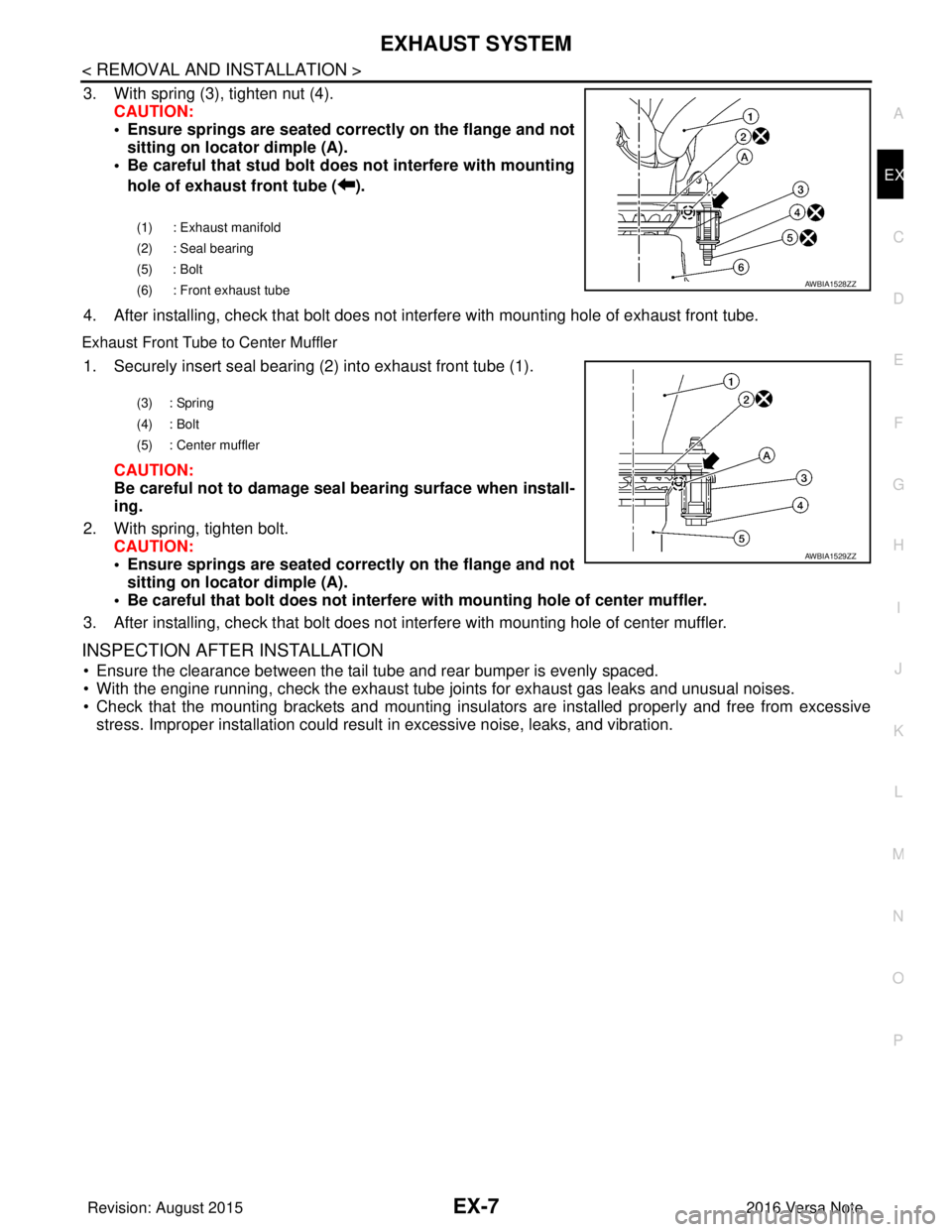
3. With spring (3), tighten nut (4).
CAUTION:
• Ensure springs are seated correctly on the flange and notsitting on locator dimple (A).
• Be careful that stud bolt do es not interfere with mounting
hole of exhaust front tube ( ).
4. After installing, check that bolt does not in terfere with mounting hole of exhaust front tube.
Exhaust Front Tube to Center Muffler
1. Securely insert seal bearing (2) into exhaust front tube (1).
CAUTION:
Be careful not to damage seal bearing surface when install-
ing.
2. With spring, tighten bolt. CAUTION:
• Ensure springs are seated correctly on the flange and notsitting on locator dimple (A).
• Be careful that bolt does not interfere with mounting hole of center muffler.
3. After installing, check that bolt does not in terfere with mounting hole of center muffler.
INSPECTION AFTER INSTALLATION
• Ensure the clearance between the tail tube and rear bumper is evenly spaced.
• With the engine running, check the exhaust tube joints for exhaust gas leaks and unusual noises.
• Check that the mounting brackets and mounting insula tors are installed properly and free from excessive
stress. Improper installation could result in excessive noise, leaks, and vibration.
(1) : Exhaust manifold
(2) : Seal bearing
(5) : Bolt
(6) : Front exhaust tube
AWBIA1528ZZ
(3) : Spring
(4) : Bolt
(5) : Center muffler
AWBIA1529ZZ
Revision: August 2015 2016 Versa Note
cardiagn.com
Page 1656 of 3641

EXL-4
< PRECAUTION >
PRECAUTIONS
PRECAUTION
PRECAUTIONS
Precaution for Supplemental Restraint System (SRS) "AIR BAG" and "SEAT BELT
PRE-TENSIONER"
INFOID:0000000012432764
The Supplemental Restraint System such as “A IR BAG” and “SEAT BELT PRE-TENSIONER”, used along
with a front seat belt, helps to reduce the risk or severity of injury to the driver and front passenger for certain
types of collision. Information necessary to service the system safely is included in the SR and SB section of
this Service Manual.
WARNING:
• To avoid rendering the SRS inopera tive, which could increase the risk of personal injury or death in
the event of a collision which would result in air bag inflation, all maintenance must be performed by
an authorized NISSAN/INFINITI dealer.
• Improper maintenance, including in correct removal and installation of the SRS, can lead to personal
injury caused by unintent ional activation of the system. For re moval of Spiral Cable and Air Bag
Module, see the SR section.
• Do not use electrical test equipmen t on any circuit related to the SRS unless instructed to in this
Service Manual. SRS wiring harn esses can be identified by yellow and/or orange harnesses or har-
ness connectors.
PRECAUTIONS WHEN USING POWER TOOLS (AIR OR ELECTRIC) AND HAMMERS
WARNING:
• When working near the Airbag Diagnosis Sensor Unit or other Airbag System sensors with the Igni-
tion ON or engine running, DO NOT use air or electri c power tools or strike near the sensor(s) with a
hammer. Heavy vibration could activate the sensor( s) and deploy the air bag(s), possibly causing
serious injury.
• When using air or electric power tools or hammers , always switch the Ignition OFF, disconnect the
battery and wait at least three minutes before performing any service.
Precaution for WorkINFOID:0000000012432765
• When removing or disassembling each component, be careful not to damage or deform it. If a component may be subject to interference, be sure to protect it with a shop cloth.
• When removing (disengaging) components with a screwdriver or similar tool, be sure to wrap the component with a shop cloth or vinyl tape to protect it.
• Protect the removed parts with a shop cloth and prevent them from being dropped.
• Replace a deformed or damaged clip.
• If a part is specified as a non-reusable part, always replace it with a new one.
• Be sure to tighten bolts and nuts securely to the specified torque.
• After installation is complete, be sure to check that each part works properly.
• Follow the steps below to clean components:
- Water soluble dirt:
• Dip a soft cloth into lukewarm water, wring the water out of the cloth and wipe the dirty area.
• Then rub with a soft, dry cloth.
- Oily dirt:
• Dip a soft cloth into lukewarm water with mild detergent (concentration: within 2 to 3%) and wipe the dirty area.
• Then dip a cloth into fresh water, wring the water out of the cloth and wipe the detergent off.
• Then rub with a soft, dry cloth.
- Do not use organic solvent such as thinner, benzene, alcohol or gasoline.
- For genuine leather seats, use a genuine leather seat cleaner.
Revision: August 2015 2016 Versa Note
cardiagn.com
Page 1658 of 3641

EXL-6
< SYSTEM DESCRIPTION >
COMPONENT PARTS
SYSTEM DESCRIPTION
COMPONENT PARTS
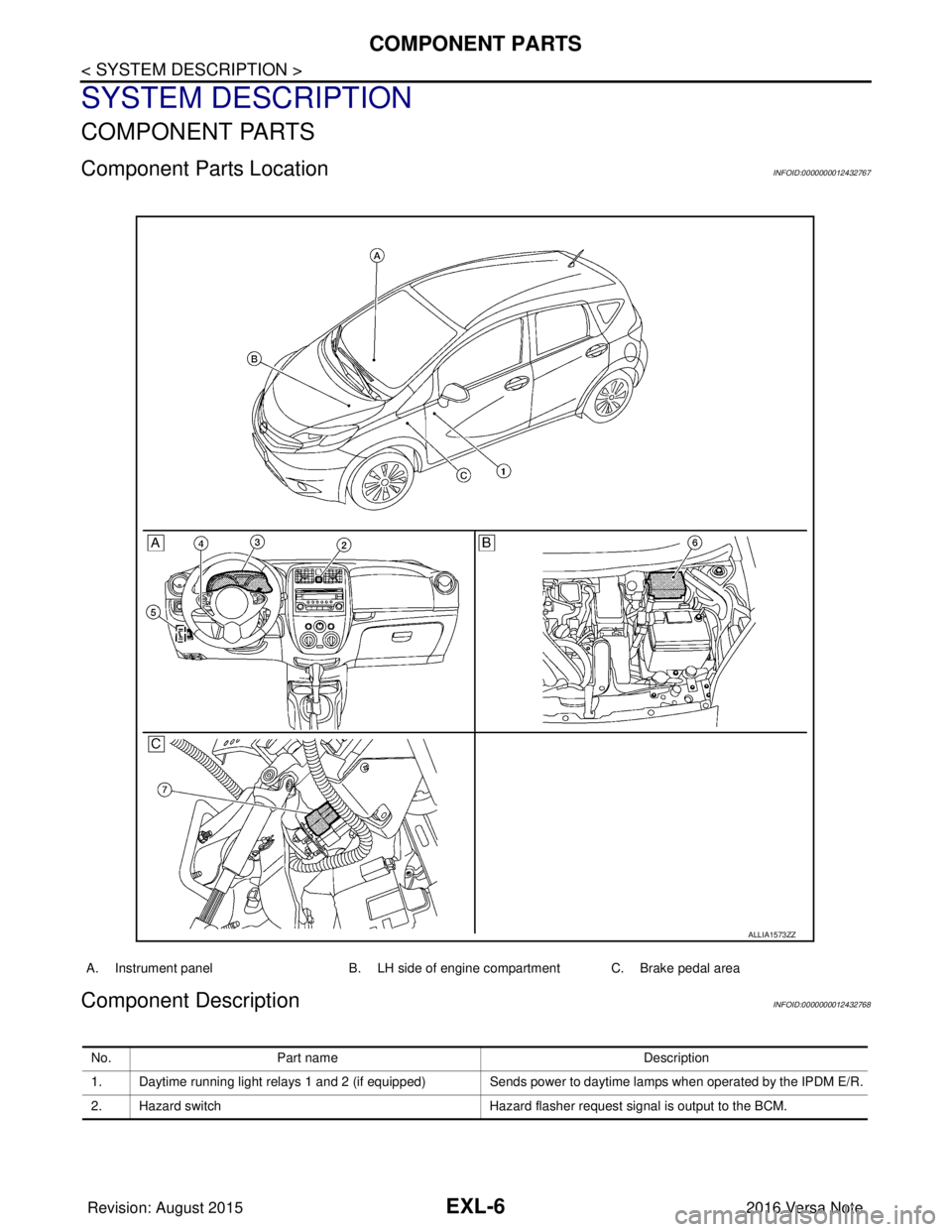
Component Parts LocationINFOID:0000000012432767
Component DescriptionINFOID:0000000012432768
A. Instrument panelB. LH side of engine compartment C. Brake pedal area
ALLIA1573ZZ
No.Part name Description
1. Daytime running light relays 1 and 2 (if equipped) Sends power to daytime lamps when operated by the IPDM E/R.
2. Hazard switch Hazard flasher request signal is output to the BCM.
Revision: August 2015 2016 Versa Note
cardiagn.com