2016 NISSAN NOTE engine
[x] Cancel search: enginePage 1869 of 3641
PRECAUTIONSFL-3
< PRECAUTION >
C
DE
F
G H
I
J
K L
M A
FL
NP
O
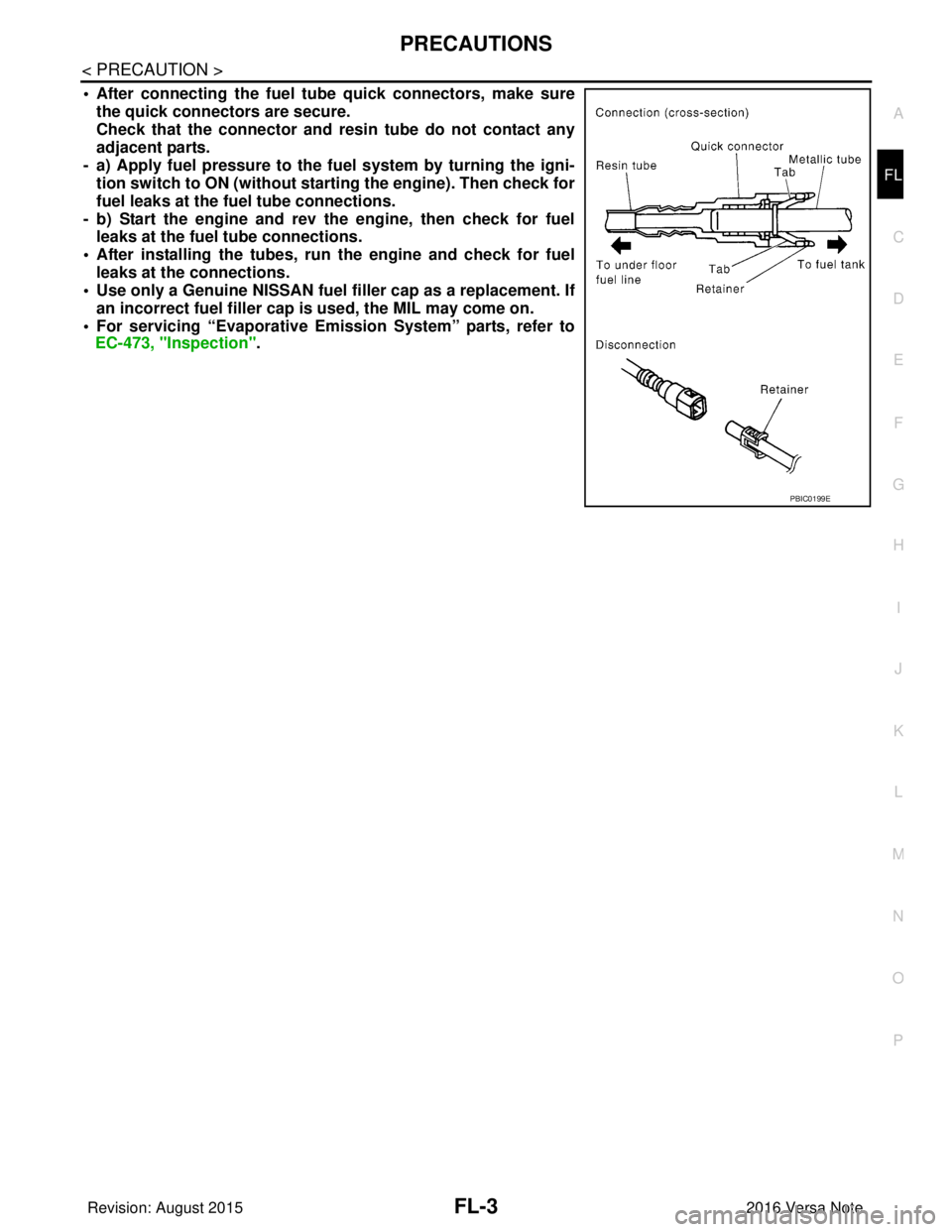
• After connecting the fuel tu
be quick connectors, make sure
the quick connectors are secure.
Check that the connector and r esin tube do not contact any
adjacent parts.
- a) Apply fuel pressure to the fu el system by turning the igni-
tion switch to ON (without starting the engine). Then check for
fuel leaks at the fuel tube connections.
- b) Start the engine and rev the engine, then check for fuel leaks at the fuel tube connections.
• After installing the tubes, run the engine and check for fuel
leaks at the connections.
• Use only a Genuine NISSAN fuel filler cap as a replacement. If
an incorrect fuel fi ller cap is used, the MIL may come on.
• For servicing “Evaporative Emi ssion System” parts, refer to
EC-473, "Inspection".
PBIC0199E
Revision: August 2015 2016 Versa Note
cardiagn.com
Page 1871 of 3641
FUEL SYSTEMFL-5
< PERIODIC MAINTENANCE >
C
DE
F
G H
I
J
K L
M A
FL
NP
O
PERIODIC MAINTENANCE
FUEL SYSTEM
InspectionINFOID:0000000012432107
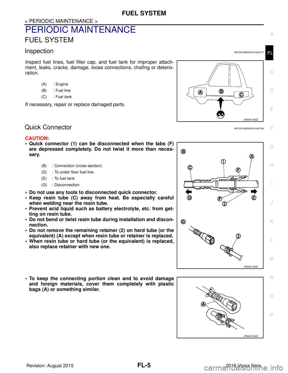
Inspect fuel lines, fuel filler cap,
and fuel tank for improper attach-
ment, leaks, cracks, damage, loos e connections, chafing or deterio-
ration.
If necessary, repair or replace damaged parts.
Quick ConnectorINFOID:0000000012432108
CAUTION:
• Quick connector (1) can be di sconnected when the tabs (F)
are depressed completely. Do not twist it more than neces-
sary.
• Do not use any tools to di sconnected quick connector.
• Keep resin tube (C) away from heat. Be especially careful when welding near the resin tube.
• Prevent acid liquid such as battery electrolyte, etc. from get- ting on resin tube.
• Do not bend or twist resin tube during installation and discon-
nection.
• Do not remove the remaining retainer (2) on hard tube (or the equivalent) (A) except when resin tu be or retainer is replaced.
• When resin tube or hard tube (or the equivalent) is replaced, also replace retainer with new one.
• To keep the connecting portion clean and to avoid damage and foreign materials, cover them completely with plastic
bags (A) or something similar.
(A) : Engine
(B) : Fuel line
(C) : Fuel tank
JPBIA0129ZZ
(B) : Connection (cross-section)
(D) : To under floor fuel line
(E) : To fuel tank
(G) : Disconnection
JPBIA0130ZZ
JPBIA0135ZZ
Revision: August 2015 2016 Versa Note
cardiagn.com
Page 1875 of 3641
FUEL LEVEL SENSOR UNIT, FUEL FILTER AND FUEL PUMP ASSEMBLYFL-9
< REMOVAL AND INSTALLATION >
C
DE
F
G H
I
J
K L
M A
FL
NP
O
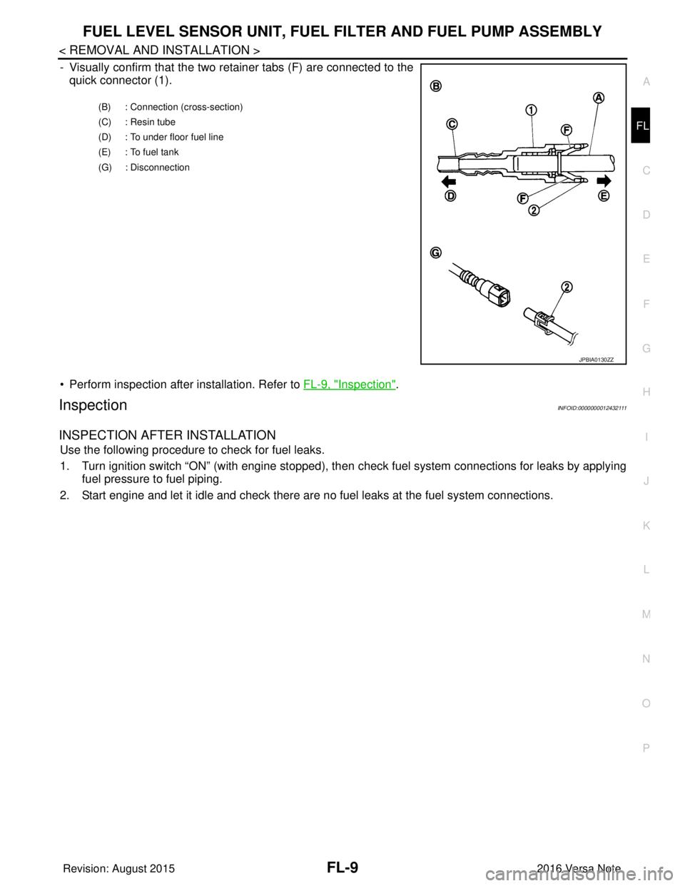
- Visually confirm that the two retainer tabs (F) are connected to the
quick connector (1).
• Perform inspection after installation. Refer to FL-9, "
Inspection".
InspectionINFOID:0000000012432111
INSPECTION AFTER INSTALLATION
Use the following procedure to check for fuel leaks.
1. Turn ignition switch “ON” (with engine stopped), then check fuel system connections for leaks by applying
fuel pressure to fuel piping.
2. Start engine and let it idle and check there are no fuel leaks at the fuel system connections.
(B) : Connection (cross-section)
(C) : Resin tube
(D) : To under floor fuel line
(E) : To fuel tank
(G) : Disconnection
JPBIA0130ZZ
Revision: August 2015 2016 Versa Note
cardiagn.com
Page 1879 of 3641
FUEL TANKFL-13
< REMOVAL AND INSTALLATION >
C
DE
F
G H
I
J
K L
M A
FL
NP
O
17. If replacing the fuel tank, remove the fuel level sensor unit, fuel filter and fuel pump assembly to transfer to
the new fuel tank.
CAUTION:
Do not reuse O-ring.
INSTALLATION
Installation is in the reverse order of removal.
Fuel Filler Hose
• Insert fuel filler hose to the length below.
• Be sure hose clamp is not placed on swelled area of fuel filler tube.
• Install fuel filler hose to fuel t ank, paying attention to install mark.
EVAP Hose
1. Check connections for damage or foreign material.
2. Align the matching side connection part with the center of shaft, and insert connector straight until a "click"
sound is heard.
InspectionINFOID:0000000012432114
INSPECTION AFTER INSTALLATION
Use the following procedure to check for fuel leaks.
1. Turn ignition switch “ON” (with engine stopped), then check fuel system connections for leaks by applying
fuel pressure to fuel piping.
2. Start engine and let it idle and check there are no fuel leaks at the fuel system connections.
Fuel filler hose : 35 mm (1.38 in)
Vent hose : 25 mm (0.98 in)
Revision: August 2015
2016 Versa Note
cardiagn.com
Page 1887 of 3641
FUEL LEVEL SENSOR UNITFL-21
< DISASSEMBLY AND ASSEMBLY >
C
DE
F
G H
I
J
K L
M A
FL
NP
O
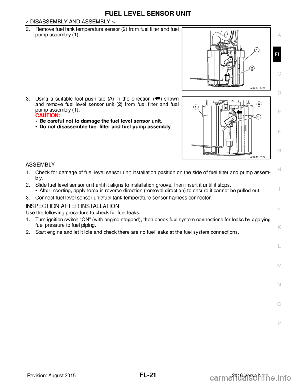
2. Remove fuel tank temperature s
ensor (2) from fuel filter and fuel
pump assembly (1).
3. Using a suitable tool push tab (A) in the direction ( ) shown and remove fuel level sensor unit (2) from fuel filter and fuel
pump assembly (1).
CAUTION:
• Be careful not to damage the fuel level sensor unit.
• Do not disassemble fuel filter and fuel pump assembly.
ASSEMBLY
1. Check for damage of fuel level sensor unit installation position on the side of fuel filter and pump assem- bly.
2. Slide fuel level sensor unit until it aligns to installation groove, then insert it until it stops. • After inserting, apply force in reverse direction (removal direction) to ensure it cannot be pulled out.
3. Connect fuel level sensor unit/fuel t ank temperature sensor harness connector.
INSPECTION AFTER INSTALLATION
Use the following procedure to check for fuel leaks.
1. Turn ignition switch “ON” (with engine stopped), then check fuel system connections for leaks by applying
fuel pressure to fuel piping.
2. Start engine and let it idle and check there are no fuel leaks at the fuel system connections.
ALBIA1134ZZ
ALBIA1135ZZ
Revision: August 2015 2016 Versa Note
cardiagn.com
Page 1889 of 3641
GI-1
GENERAL INFORMATION
C
DE
F
G H
I
J
K L
M B
GI
SECTION GI
N
O P
CONTENTS
GENERAL INFORMATION
HOW TO USE THIS MANU AL ......................3
HOW TO USE THIS MANUAL ....................... .....3
Description .......................................................... ......3
Terms ........................................................................3
Units ..........................................................................3
Contents ....................................................................3
Relation between Illustrations and Descriptions .......4
Components ..............................................................4
HOW TO FOLLOW TROUBLE DIAGNOSES .....6
Description ................................................................6
How to Follow Test Groups in Trouble Diagnosis ......6
Key to Symbols Signifying Measurements or Pro-
cedures ............................................................... ......
7
HOW TO READ WIRING DIAGRAMS ................9
Connector Symbols ............................................. ......9
Sample/Wiring Diagram -Example- .........................10
Connector Information .............................................12
ABBREVIATIONS .......................................... ....14
Abbreviation List .................................................. ....14
TIGHTENING TORQUE OF STANDARD
BOLTS ................................................................
19
Description .......................................................... ....19
Tightening Torque Table (New Standard Includ-
ed) ...........................................................................
19
RECOMMENDED CHEMICAL PRODUCTS
AND SEALANTS ................................................
22
Recommended Chemical Products and Sealants ....22
PRECAUTION ..............................................23
PRECAUTIONS .............................................. ....23
Description .......................................................... ....23
Precaution for Supplemental Restraint System
(SRS) "AIR BAG" and "SEAT BELT PRE-TEN-
SIONER" .................................................................
23
Procedures without Cowl Top Cover .......................23
Cautions in Removing Battery Terminal and AV
Control Unit (Models with AV Control Unit) .............
23
General Precautions ............................................ ....24
Three Way Catalyst .................................................25
Fuel ..........................................................................25
Multiport Fuel Injection System or Engine Control
System .....................................................................
26
Hoses ......................................................................26
Engine Oils ..............................................................27
Air Conditioning .......................................................27
LIFTING POINT .................................................28
Special Service Tool ................................................28
Garage Jack and Safety Stand ................................28
2-Pole Lift ................................................................29
Board-on Lift ............................................................30
TOW TRUCK TOWING .....................................31
Tow Truck Towing ...................................................31
Vehicle Recovery (Freeing a Stuck Vehicle) ...........31
VEHICLE INFORMATION ...........................33
IDENTIFICATION INFORMATION ....................33
Model Variation .................................................... ....33
Identification Number ...............................................34
Identification Plate ...................................................35
Engine Serial Number .............................................36
CVT Number ............................................................36
Manual Transaxle Number ......................................36
Dimensions ..............................................................36
Wheels & Tires ........................................................37
BASIC INSPECTION ...................................38
SERVICE INFORMATION FOR ELECTRICAL
INCIDENT ..........................................................
38
Work Flow ............................................................ ....38
Control Units and Electrical Parts ............................38
How to Check Terminal ...........................................39
Intermittent Incident ............................................. ....42
Circuit Inspection .....................................................44
Revision: August 2015 2016 Versa Note
cardiagn.com
Page 1903 of 3641
ABBREVIATIONSGI-15
< HOW TO USE THIS MANUAL >
C
DE
F
G H
I
J
K L
M B
GI
N
O P
E
F
G
H
DLC Data link connector
DTC Diagnostic trouble code
ABBREVIATION DESCRIPTION
E/T Exhaust temperature
EBD Electric brake force distribution
EC Engine control
ECL Engine coolant level
ECM Engine control module
ECT Engine coolant temperature
ECV Electrical control valve
EEPROM Electrically erasable programmable read only memory EFT Engine fuel temperature
EGR Exhaust gas recirculation
EGRT Exhaust gas recirculation temperature EGT Exhaust gas temperature
EOP Engine oil pressure
EP Exhaust pressure
EPR Exhaust pressure regulator
EPS Electronically controlled power steering
ESP Electronic stability program system
EVAP canister Evaporative emission canister EVSE Electric vehicle supply equipment
EXC Exhaust control
ABBREVIATION DESCRIPTION
FC Fan control
FCW Forward collision warning
FIC Fuel injector control
FP Fuel pump
FR Front
FRP Fuel rail pressure
FRT Fuel rail temperature
FTP Fuel tank pressure
FTT Fuel tank temperature
ABBREVIATION DESCRIPTION
GND Ground
GPS Global positioning system
GST Generic scan tool
ABBREVIATION DESCRIPTION
HBMC Hydraulic body-motion control system HDD Hard disk drive
HO2S Heated oxygen sensor
ABBREVIATION
DESCRIPTION
Revision: August 2015 2016 Versa Note
cardiagn.com
Page 1904 of 3641

GI-16
< HOW TO USE THIS MANUAL >
ABBREVIATIONS
I
K
L
M
N
HOCHeated oxidation catalyst
HPCM Hybrid power train control module
ABBREVIATION DESCRIPTION
I/M Inspection and maintenance
IA Intake air
IAC Idle air control
IAT Intake air temperature
IBA Intelligent brake assist
IC Ignition control
ICC Intelligent cruise control
ICM Ignition control module
IPDM E/R Intelligent power distribution module engine room ISC Idle speed control
ISS Input shaft speed
ITS Information technology suite
ABBREVIATION DESCRIPTION
KS Knock sensor
ABBREVIATION DESCRIPTION
LBC Li-ion battery controller
LCD Liquid crystal display
LCU Local control unit
LDP Lane departure prevention
LDW Lane departure warning
LED Light emitting diode
LH Left-hand
LHD Left-hand drive
LIN Local interconnect network
ABBREVIATION DESCRIPTION
M/T Manual transaxle/transmission
MAF Mass airflow
MAP Manifold absolute pressure
MDU Multi display unit
MI Malfunction indicator
MIL Malfunction indicator lamp
MOD Moving object detection
ABBREVIATION DESCRIPTION
NOX Nitrogen oxides
ABBREVIATION
DESCRIPTION
Revision: August 2015 2016 Versa Note
cardiagn.com