2016 NISSAN NOTE engine
[x] Cancel search: enginePage 1752 of 3641
EXL-100
< PERIODIC MAINTENANCE >
FRONT FOG LAMP AIMING ADJUSTMENT
FRONT FOG LAMP AIMING ADJUSTMENT
InspectionINFOID:0000000012432830
PREPARATION BEFORE ADJUSTING
Before performing aiming adjustment procedure, check the following:
• Ensure all tires are inflated to correct pressure.
• Place vehicle and screen on level surface.
• Ensure there is no load in vehicle other than the driver (or equivalent weight placed in driver's position).
• Coolant and engine oil filled to correct level, and fuel tank full.
• Remove cargo and/or luggage to maintain an unloaded vehicle condition.
• Confirm spare tire, jack and tools are properly stowed.
• Carefully wipe off any dirt from fog lamp lens. CAUTION:
Do not use organic solvent (thinner, gasoline etc.)
• Place a driver or equivalent weight of 68.5 kg (150 lb) on the driver seat.
• By hand, bounce the front and rear of the vehicle to settle the suspension and eliminate any static load.
• Place the front tires in the straight ahead position.
• Aim each headlamp individually and ensure other headlamp beam pattern is blocked from screen.
NOTE:
• For headlamp aiming details, refer to regulations in your area.
• By regulation, no means for horizontal aim adjustment is provided from the factory; only vertical aim is
adjustable.
• Use adjusting screw to perform aiming adjustment.
• Perform headlamp aiming if:
- The vehicle front body has been repaired.
- The front combination lamp has been removed or replaced.
- Any outfitting has been installed.
- The vehicle’s standard load condition has been substantially increased.
AIMING ADJUSTMENT SCREW
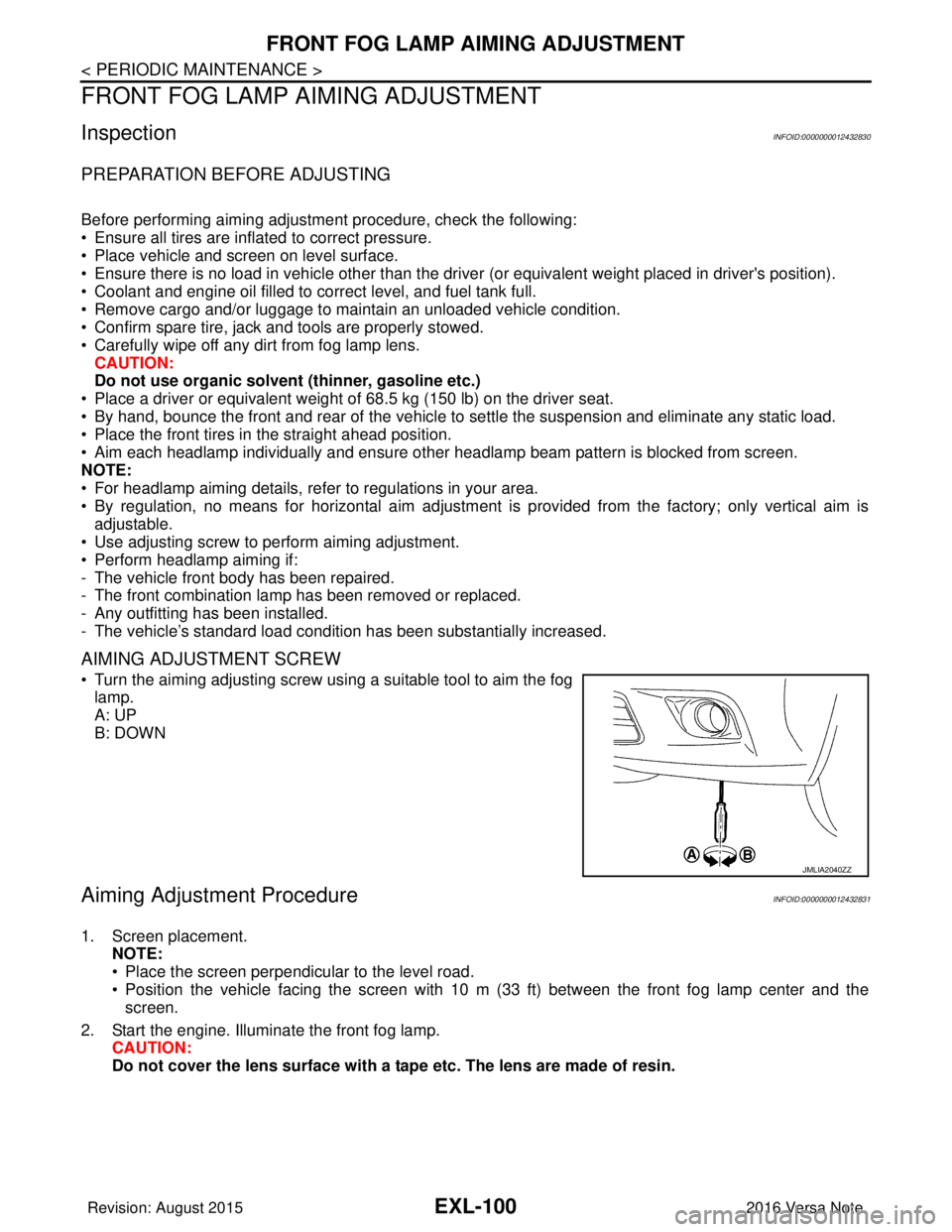
• Turn the aiming adjusting screw using a suitable tool to aim the fog
lamp.
A: UP
B: DOWN
Aiming Adjustment ProcedureINFOID:0000000012432831
1. Screen placement. NOTE:
• Place the screen perpendicular to the level road.
• Position the vehicle facing the screen with 10 m (33 ft) between the front fog lamp center and thescreen.
2. Start the engine. Illuminate the front fog lamp. CAUTION:
Do not cover the lens surface with a tape etc. The lens are made of resin.
JMLIA2040ZZ
Revision: August 2015 2016 Versa Note
cardiagn.com
Page 1770 of 3641
PRECAUTIONSEXT-3
< PRECAUTION >
C
DE
F
G H
I
J
L
M A
B
EXT
N
O P
PRECAUTION
PRECAUTIONS
Precaution for Supplemental Restraint System (SRS) "AIR BAG" and "SEAT BELT
PRE-TENSIONER"
INFOID:0000000012432151
The Supplemental Restraint System such as “AIR BAG” and “SEAT BELT PRE-TENSIONER”, used along
with a front seat belt, helps to reduce the risk or severi ty of injury to the driver and front passenger for certain
types of collision. Information necessary to service the system safely is included in the SR and SB section of
this Service Manual.
WARNING:
• To avoid rendering the SRS inoper ative, which could increase the risk of personal injury or death in
the event of a collision which would result in air bag inflation, all maintenance must be performed by
an authorized NISSAN/INFINITI dealer.
• Improper maintenance, including in correct removal and installation of the SRS, can lead to personal
injury caused by unintentional act ivation of the system. For removal of Spiral Cable and Air Bag
Module, see the SR section.
• Do not use electrical test equipm ent on any circuit related to the SRS unless instructed to in this
Service Manual. SRS wiring harnesses can be identi fied by yellow and/or orange harnesses or har-
ness connectors.
PRECAUTIONS WHEN USING POWER TOOLS (AIR OR ELECTRIC) AND HAMMERS
WARNING:
• When working near the Airbag Diagnosis Sensor Un it or other Airbag System sensors with the Igni-
tion ON or engine running, DO NOT use air or el ectric power tools or strike near the sensor(s) with a
hammer. Heavy vibration could activate the sensor( s) and deploy the air bag(s), possibly causing
serious injury.
• When using air or electric power tools or hammers, always switch the Ignition OFF, disconnect the
battery and wait at least three mi nutes before performing any service.
Procedure without Cowl Top CoverINFOID:0000000012432152
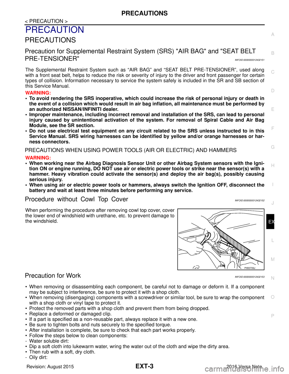
When performing the procedure after removing cowl top cover, cover
the lower end of windshield with urethane, etc. to prevent damage to
the windshield.
Precaution for WorkINFOID:0000000012432153
• When removing or disassembling each component, be ca reful not to damage or deform it. If a component
may be subject to interference, be sure to protect it with a shop cloth.
• When removing (disengaging) components with a screwdriver or similar tool, be sure to wrap the component with a shop cloth or vinyl tape to protect it.
• Protect the removed parts with a shop cloth and prevent them from being dropped.
• Replace a deformed or damaged clip.
• If a part is specified as a non-reusabl e part, always replace it with a new one.
• Be sure to tighten bolts and nuts securely to the specified torque.
• After installation is complete, be sure to check that each part works properly.
• Follow the steps below to clean components:
- Water soluble dirt:
• Dip a soft cloth into lukewarm water, wring the water out of the cloth and wipe the dirty area.
• Then rub with a soft, dry cloth.
-Oily dirt:
PIIB3706J
Revision: August 2015 2016 Versa Note
cardiagn.com
Page 1772 of 3641
PREPARATIONEXT-5
< PREPARATION >
C
DE
F
G H
I
J
L
M A
B
EXT
N
O P
PREPARATION
PREPARATION
Special Service ToolsINFOID:0000000012432154
The actual shape of the tools may di ffer from those illustrated here.
Commercial Service ToolsINFOID:0000000012432155
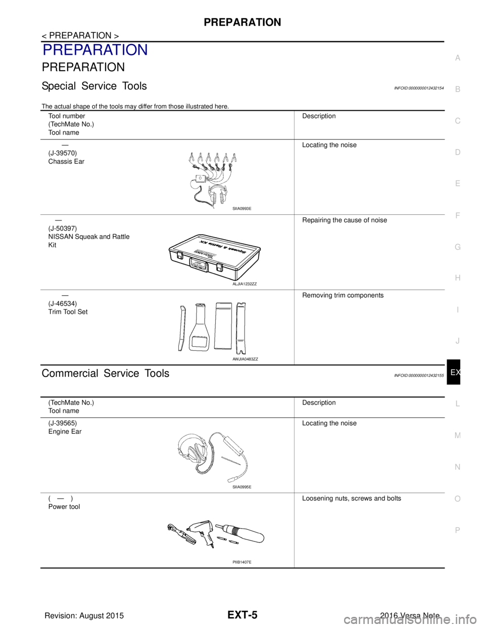
Tool number
(TechMate No.)
Tool name Description
—
(J-39570)
Chassis Ear Locating the noise
—
(J-50397)
NISSAN Squeak and Rattle
Kit Repairing the cause of noise
—
(J-46534)
Trim Tool Set Removing trim components
SIIA0993E
ALJIA1232ZZ
AWJIA0483ZZ
(TechMate No.)
Tool name
Description
(J-39565)
Engine Ear Locating the noise
(—)
Power tool Loosening nuts, screws and bolts
SIIA0995E
PIIB1407E
Revision: August 2015
2016 Versa Note
cardiagn.com
Page 1777 of 3641
EXT-10
< SYSTEM DESCRIPTION >
COMPONENT PARTS
SYSTEM DESCRIPTION
COMPONENT PARTS
ACTIVE GRILLE SHUTTER SYSTEM
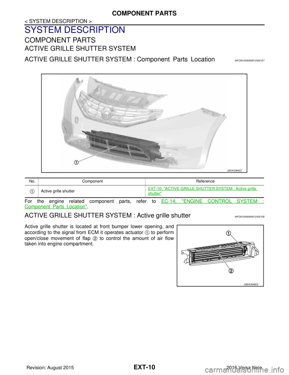
ACTIVE GRILLE SHUTTER SYSTEM : Component Parts LocationINFOID:0000000012432157
For the engine related component parts, refer to EC-14, "ENGINE CONTROL SYSTEM :
ComponentPartsLocation".
ACTIVE GRILLE SHUTTER SYSTEM : Active grille shutterINFOID:0000000012432158
Active grille shutter is located at front bumper lower opening, and
according to the signal from ECM it operates actuator to perform
open/close movement of flap to control the amount of air flow
taken into engine compartment.
JSKIA3360ZZ
No.Component Reference
Active grille shutter EXT-10, "
ACTIVE GRILLE SHUTTER SYSTEM : Active grille
shutter"
JSBIA3648ZZ
Revision: August 2015
2016 Versa Note
cardiagn.com
Page 1778 of 3641
SYSTEMEXT-11
< SYSTEM DESCRIPTION >
C
DE
F
G H
I
J
L
M A
B
EXT
N
O P
SYSTEM
ACTIVE GRILLE SHUTTER SYSTEM
ACTIVE GRILLE SHUTTER SYSTEM : System DiagramINFOID:0000000012432159
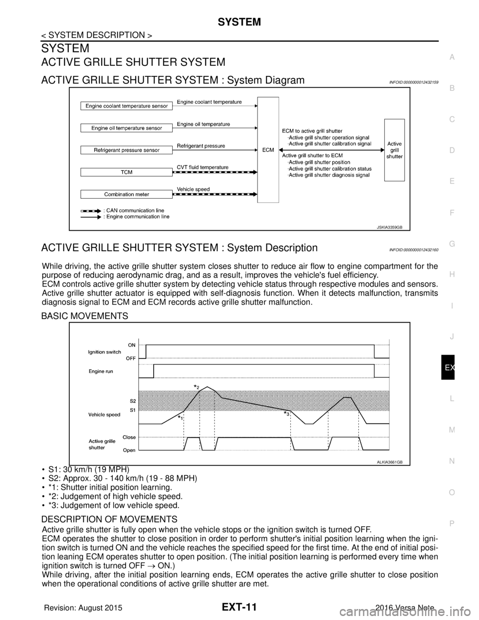
ACTIVE GRILLE SHUTTER SYSTEM : System DescriptionINFOID:0000000012432160
While driving, the active grille shutter system closes shutter to reduce air flow to engine compartment for the
purpose of reducing aerodynamic drag, and as a resu lt, improves the vehicle's fuel efficiency.
ECM controls active grille shutter system by detecting vehicle status through respective modules and sensors.
Active grille shutter actuator is equipped with self-d iagnosis function. When it detects malfunction, transmits
diagnosis signal to ECM and ECM records active grille shutter malfunction.
BASIC MOVEMENTS
• S1: 30 km/h (19 MPH)
• S2: Approx. 30 - 140 km/h (19 - 88 MPH)
• *1: Shutter initial position learning.
• *2: Judgement of high vehicle speed.
• *3: Judgement of low vehicle speed.
DESCRIPTION OF MOVEMENTS
Active grille shutter is fully open when the vehicl e stops or the ignition switch is turned OFF.
ECM operates the shutter to close position in order to perform shutter's initial position learning when the igni-
tion switch is turned ON and the vehicle reaches the specified speed for the first time. At the end of initial posi-
tion leaning ECM operates shutter to open position. (The in itial position learning is performed every time when
ignition switch is turned OFF → ON.)
While driving, after the initial position learning ends, EC M operates the active grille shutter to close position
when the operational conditions of active grille shutter are met.
JSKIA3359GB
ALKIA3661GB
Revision: August 2015 2016 Versa Note
cardiagn.com
Page 1779 of 3641

EXT-12
< SYSTEM DESCRIPTION >
SYSTEM
While driving at high speed, ECM operates the shutter to open position when the vehicle reaches the specified
speed in order to prevent the shutte r from shutting up by wind resistance.
When the vehicle speed is reduced below the specified speed ECM operates active grille shutter to open posi-
tion.
ACTIVE GRILLE SHUTTER OPERATIONAL CONDITIONS
ECM operates active grille shutter to close position when following a ll conditions are met.
ECM operates active grille shutter to open positi on when one of the following conditions is met.
Item Status
Active grille shutter initial position learning Complete
Vehicle speed Approx. 30 - 140 km/h (19 - 88 MPH)
Engine coolant temperature Approx. less than 95°C (203 °F)
Engine oil temperature Approx. less than 140°C (284 °F)
CVT fluid temperature Approx. less than 135°C (275 °F)
Cooling fan OFF
Refrigerant pressure 0.78 MPa (7.95 kg/cm
2, 113.1 psi) or less
Malfunction of engine coolant temperature sensor system Not detected
Malfunction of engine oil temperature sensor system Not detected
Malfunction of vehicle speed sensor system Not detected
Malfunction of CAN communication system Not detected
ItemStatus
Vehicle speed • 22 km/h (14 MPH) or less
• 140 km/h (88 MPH) or more
Engine coolant temperature Approx. 95°C (203 °F) or more
Engine oil temperature Approx. 140°C (284 °F) or more
CVT fluid temperature Approx. 135°C (275 °F) or more
Cooling fan ON
Refrigerant pressure 1.18 MPa (12.04 kg/cm
2, 171.1 psi) or more
Malfunction of engine coolant temperature sensor system Detected
Malfunction of engine oil temperature sensor system Detected
Malfunction of vehicle speed sensor system Detected
Malfunction of CAN communication system Detected
Revision: August 2015 2016 Versa Note
cardiagn.com
Page 1785 of 3641
EXT-18
< SYMPTOM DIAGNOSIS >
SQUEAK AND RATTLE TROUBLE DIAGNOSES
If possible, drive the vehicle with the customer until the noise is duplicated. Note any additional information on
the Diagnostic Worksheet regarding the conditions or lo cation of the noise. This information can be used to
duplicate the same conditions when you confirm the repair.
If the noise can be duplicated easily during the test drive, to help identify the source of the noise, try to dupli-
cate the noise with the vehicle stopped by doing one or all of the following:
1) Close a door.
2) Tap or push/pull around the area where the noise appears to be coming from.
3) Rev the engine.
4) Use a floor jack to recreate vehicle “twist”.
5) At idle, apply engine load (electrical load, half-clutch on M/T model, drive position on CVT and A/T models).
6) Raise the vehicle on a hoist and hit a tire with a rubber hammer.
• Drive the vehicle and attempt to duplicate the conditions the customer states exist when the noise occurs.
• If it is difficult to duplicate the noise, drive the v ehicle slowly on an undulating or rough road to stress the
vehicle body.
CHECK RELATED SERVICE BULLETINS
After verifying the customer concern or symptom, chec k ASIST for Technical Service Bulletins (TSBs) related
to that concern or symptom.
If a TSB relates to the symptom, follo w the procedure to repair the noise.
LOCATE THE NOISE AND IDENTIFY THE ROOT CAUSE
1. Narrow down the noise to a general area. To help pi npoint the source of the noise, use a listening tool
(Chassis Ear: J-39570, Engine Ear: J-39565 and mechanic's stethoscope).
2. Narrow down the noise to a more specific area and identify the cause of the noise by: • removing the components in the area that you suspect the noise is coming from.Do not use too much force when removing clips and fasteners, otherwise clips and fasteners can be
broken or lost during the repair, resulting in the creation of new noise.
• tapping or pushing/pulling the component that you suspect is causing the noise. Do not tap or push/pull the component with excessive force, otherwise the noise will be eliminated only
temporarily.
• feeling for a vibration with your hand by touching the component(s) that you suspec t is (are) causing the
noise.
• placing a piece of paper between components that you suspect are causing the noise.
• looking for loose components and contact marks.
Refer to EXT-18, "
Generic Squeak and Rattle Troubleshooting".
REPAIR THE CAUSE
• If the cause is a loose component, tighten the component securely.
• If the cause is insufficient clearance between components:
- separate components by repositioning or loos ening and retightening the component, if possible.
- insulate components with a suitable insulator such as urethane pads, foam blocks, felt cloth tape or urethane tape. A NISSAN Squeak and Rattle Kit (J-50397) is av ailable through your authorized NISSAN Parts Depart-
ment.
CAUTION:
Do not use excessive force as many components are constructed of plastic and may be damaged.
NOTE:
• Always check with the Parts Department for the latest parts information.
• The materials contained in the NISSAN Squeak and Rattle Kit (J-50397) are listed on the inside cover of the
kit; and can each be ordered separately as needed.
• The following materials not found in the kit can also be used to repair squeaks and rattles.
- SILICONE GREASE: Use instead of UHMW tape that will be visible or does not fit. The silicone grease will only last a few months.
- SILICONE SPRAY: Use when grease cannot be applied.
- DUCT TAPE: Use to eliminate movement.
CONFIRM THE REPAIR
Confirm that the cause of a noise is repaired by test driving the vehicle. Operate the vehicle under the same
conditions as when the noise originally occurred. Refer to the notes on the Diagnostic Worksheet.
Generic Squeak and Rattle TroubleshootingINFOID:0000000012432163
Refer to Table of Contents for specific component removal and installation information.
Revision: August 2015 2016 Versa Note
cardiagn.com
Page 1787 of 3641

EXT-20
< SYMPTOM DIAGNOSIS >
SQUEAK AND RATTLE TROUBLE DIAGNOSES
1. Loose harness or harness connectors.
2. Front console map/reading lamp lens loose.
3. Loose screws at console attachment points.
SEATS
When isolating seat noise it's important to note the position the seat is in and the load placed on the seat when
the noise is present. These conditions should be duplicated when verifying and isolating the cause of the
noise.
Cause of seat noise include:
1. Headrest rods and holder
2. A squeak between the seat pad cushion and frame
3. The rear seatback lock and bracket
These noises can be isolated by moving or pressing on the suspected components while duplicating the con-
ditions under which the noise occurs. Most of thes e incidents can be repaired by repositioning the component
or applying urethane tape to the contact area.
UNDERHOOD
Some interior noise may be caused by components under the hood or on the engine wall. The noise is then
transmitted into the passenger compartment.
Causes of transmitted underhood noise include:
1. Any component installed to the engine wall
2. Components that pass through the engine wall
3. Engine wall mounts and connectors
4. Loose radiator installation pins
5. Hood bumpers out of adjustment
6. Hood striker out of adjustment
These noises can be difficult to isolate since they cannot be reached from the interior of the vehicle. The best
method is to secure, move or insulate one component at a time and test drive the vehicle. Also, engine rpm or
load can be changed to isolate the noise. Repairs can usually be made by moving, adjusting, securing, or
insulating the component causing the noise.
Revision: August 2015 2016 Versa Note
cardiagn.com