2016 NISSAN NOTE engine
[x] Cancel search: enginePage 1922 of 3641
GI-34
< VEHICLE INFORMATION >
IDENTIFICATION INFORMATION
Identification Number
INFOID:0000000012433176
Vehicle Identification Number Arrangement
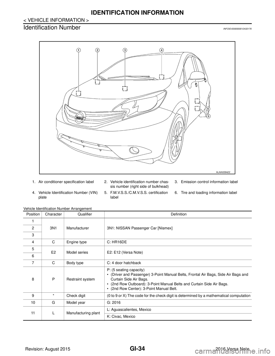
1. Air conditioner specification label 2. Vehicle identification number chas- sis number (right side of bulkhead)3. Emission control information label
4. Vehicle Identification Number (VIN) plate 5. F.M.V.S.S./C.M.V.S.S. certification
label 6. Tire and loading information label
ALAIA0094ZZ
Position Character Qualifier
Definition
1 3N1 Manufacturer 3N1: NISSAN Passenger Car [Nismex]
2
3
4 C Engine type C: HR16DE
5 E2 Model series E2: E12 (Versa Note)
6
7 C Body type C: 4 door hatchback
8 P Restraint system P: (5 seating capacity)
• (Driver and Passenger) 3-Point Manual Belts, Frontal Air Bags, Side Air Bags and
Curtain Side Air Bags.
• (2nd Row Outboard): 3-Point Manual Belts and Curtain Side Air Bags.
• (2nd Row Center): 3-Point Manual Belt.
9 * Check digit (0 to 9 or X) The code for the check digit is determined by a mathematical computation
10 G Model year G: 2016
11 L Manufacturing plant L: Aguascalientes, Mexico
K: Civac, Mexico
Revision: August 2015
2016 Versa Note
cardiagn.com
Page 1924 of 3641
GI-36
< VEHICLE INFORMATION >
IDENTIFICATION INFORMATION
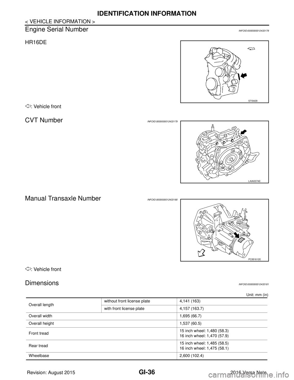
Engine Serial Number
INFOID:0000000012433178
HR16DE
: Vehicle front
CVT NumberINFOID:0000000012433179
Manual Transaxle NumberINFOID:0000000012433180
: Vehicle front
DimensionsINFOID:0000000012433181
Unit: mm (in)
STI0429
LAIA0074E
PCIB1612E
Overall length without front license plate 4,141 (163)
with front license plate
4,157 (163.7)
Overall width 1,695 (66.7)
Overall height 1,537 (60.5)
Front tread 15 inch wheel: 1,480 (58.3)
16 inch wheel: 1,470 (57.9)
Rear tread 15 inch wheel: 1,485 (58.5)
16 inch wheel: 1,475 (58.1)
Wheelbase 2,600 (102.4)
Revision: August 2015 2016 Versa Note
cardiagn.com
Page 1926 of 3641
GI-38
< BASIC INSPECTION >
SERVICE INFORMATION FOR ELECTRICAL INCIDENT
BASIC INSPECTION
SERVICE INFORMATION FOR ELECTRICAL INCIDENT
Work FlowINFOID:0000000012433183
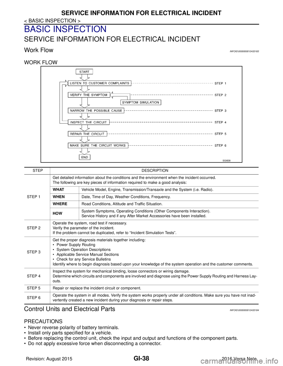
WORK FLOW
Control Units and Electrical PartsINFOID:0000000012433184
PRECAUTIONS
• Never reverse polarity of battery terminals.
• Install only parts specified for a vehicle.
• Before replacing the control unit, check the i nput and output and functions of the component parts.
• Do not apply excessive force when disconnecting a connector.
SGI838
STEP DESCRIPTION
STEP 1 Get detailed information about the conditions and the environment when the incident occurred.
The following are key pieces of information required to make a good analysis:
WHAT
Vehicle Model, Engine, Transmission/Transaxle and the System (i.e. Radio).
WHEN Date, Time of Day, Weather Conditions, Frequency.
WHERE Road Conditions, Altitude and Traffic Situation.
HOW System Symptoms, Operating Conditions
(Other Components Interaction).
Service History and if any After Market Accessories have been installed.
STEP 2 Operate the system, road test if necessary.
Verify the parameter of the incident.
If the problem cannot be duplicated, refer to “Incident Simulation Tests”.
STEP 3 Get the proper diagnosis materials together including:
• Power Supply Routing
• System Operation Descriptions
• Applicable Service Manual Sections
• Check for any Service Bulletins
Identify where to begin diagnosis based upon your knowledge of the system operation and the customer comments.
STEP 4 Inspect the system for mechanical binding, loose connectors or wiring damage.
Determine which circuits and components are involved and diagnose using the Power Supply Routing and Harness Lay-
outs.
STEP 5 Repair or replace the incident circuit or component.
STEP 6 Operate the system in all modes. Verify the system works properly under all conditions. Make sure you have not inad-
vertently created a new incident during your diagnosis or repair steps.
Revision: August 2015
2016 Versa Note
cardiagn.com
Page 1930 of 3641
GI-42
< BASIC INSPECTION >
SERVICE INFORMATION FOR ELECTRICAL INCIDENT
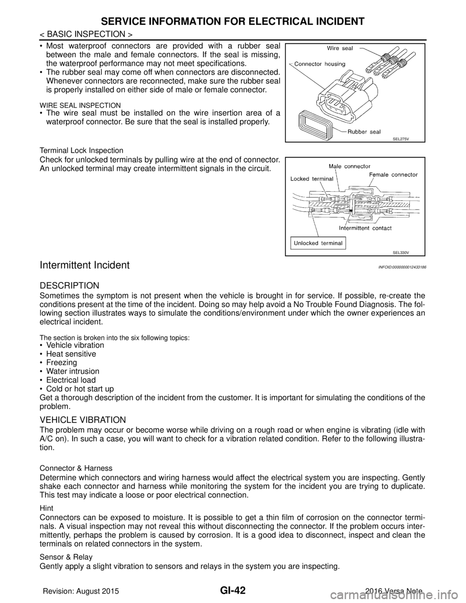
• Most waterproof connectors are provided with a rubber sealbetween the male and female connectors. If the seal is missing,
the waterproof performance may not meet specifications.
• The rubber seal may come off when connectors are disconnected. Whenever connectors are reconnected, make sure the rubber seal
is properly installed on either side of male or female connector.
WIRE SEAL INSPECTION
• The wire seal must be installed on the wire insertion area of awaterproof connector. Be sure that the seal is installed properly.
Terminal Lock Inspection
Check for unlocked terminals by pulling wire at the end of connector.
An unlocked terminal may create intermittent signals in the circuit.
Intermittent IncidentINFOID:0000000012433186
DESCRIPTION
Sometimes the symptom is not present when the vehicle is brought in for service. If possible, re-create the
conditions present at the time of the incident. Doi ng so may help avoid a No Trouble Found Diagnosis. The fol-
lowing section illustrates ways to simulate the condi tions/environment under which the owner experiences an
electrical incident.
The section is broken into the six following topics:
• Vehicle vibration
• Heat sensitive
• Freezing
• Water intrusion
• Electrical load
• Cold or hot start up
Get a thorough description of the incident from the customer. It is important for simulating the conditions of the
problem.
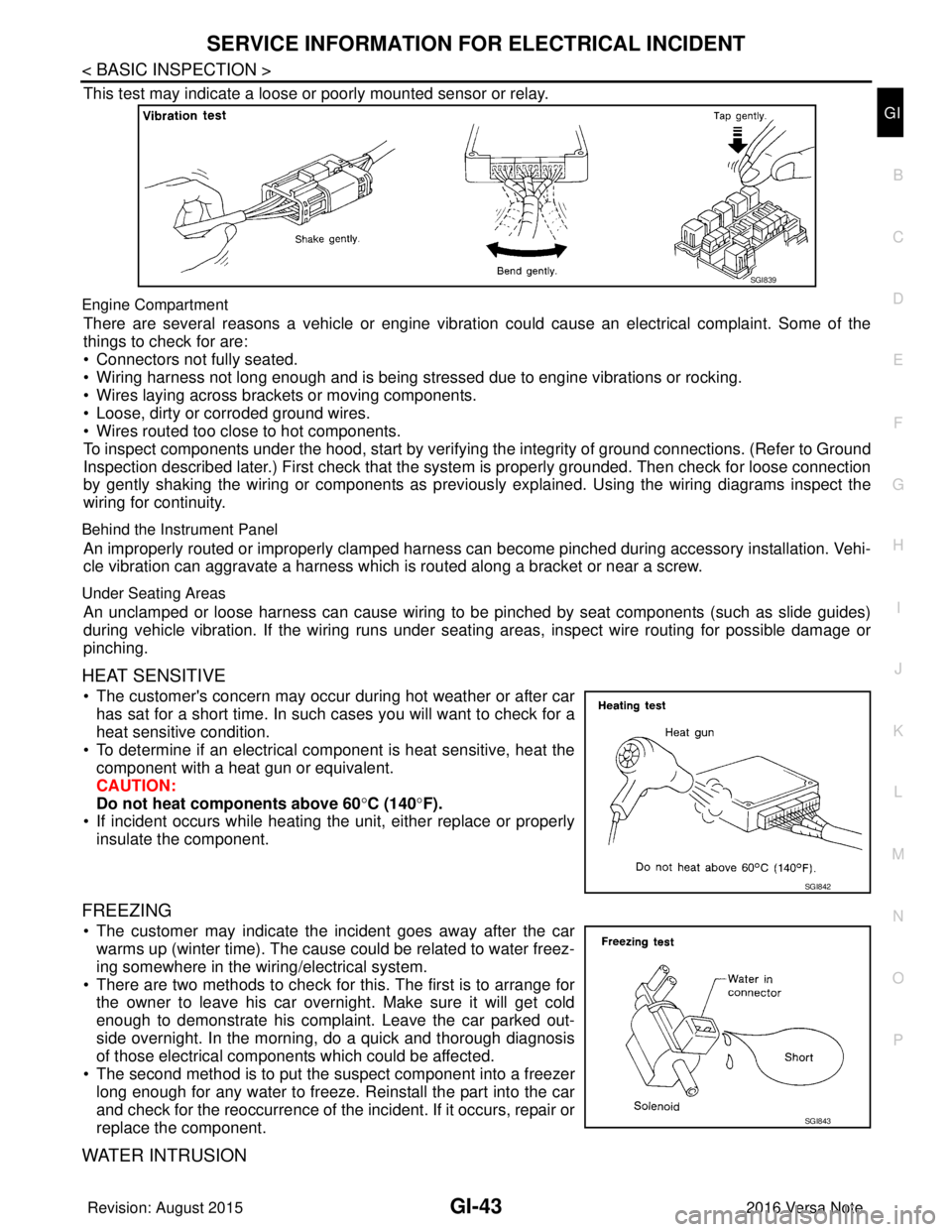
VEHICLE VIBRATION
The problem may occur or become worse while driving on a rough road or when engine is vibrating (idle with
A/C on). In such a case, you will want to check for a vi bration related condition. Refer to the following illustra-
tion.
Connector & Harness
Determine which connectors and wiring harness would affect the electrical system you are inspecting. Gently
shake each connector and harness while monitoring the sy stem for the incident you are trying to duplicate.
This test may indicate a loose or poor electrical connection.
Hint
Connectors can be exposed to moisture. It is possible to get a thin film of corrosion on the connector termi-
nals. A visual inspection may not reveal this without disconnecting the connector. If the problem occurs inter-
mittently, perhaps the problem is caused by corrosion. It is a good idea to disconnect, inspect and clean the
terminals on related connectors in the system.
Sensor & Relay
Gently apply a slight vibration to sensors and relays in the system you are inspecting.
SEL275V
SEL330V
Revision: August 2015 2016 Versa Note
cardiagn.com
Page 1931 of 3641
SERVICE INFORMATION FOR ELECTRICAL INCIDENTGI-43
< BASIC INSPECTION >
C
DE
F
G H
I
J
K L
M B
GI
N
O P
This test may indicate a loose or poorly mounted sensor or relay.
Engine Compartment
There are several reasons a vehicle or engine vibration could cause an electrical complaint. Some of the
things to check for are:
• Connectors not fully seated.
• Wiring harness not long enough and is being stressed due to engine vibrations or rocking.
• Wires laying across brackets or moving components.
• Loose, dirty or corroded ground wires.
• Wires routed too close to hot components.
To inspect components under the hood, start by verifyi ng the integrity of ground connections. (Refer to Ground
Inspection described later.) First check that the system is properly grounded. Then check for loose connection
by gently shaking the wiring or components as previous ly explained. Using the wiring diagrams inspect the
wiring for continuity.
Behind the Instrument Panel
An improperly routed or improperly clamped harness can become pinched during accessory installation. Vehi-
cle vibration can aggravate a harness which is routed along a bracket or near a screw.
Under Seating Areas
An unclamped or loose harness can cause wiring to be pinched by seat components (such as slide guides)
during vehicle vibration. If the wiring runs under s eating areas, inspect wire routing for possible damage or
pinching.
HEAT SENSITIVE
• The customer's concern may occur during hot weather or after car has sat for a short time. In such cases you will want to check for a
heat sensitive condition.
• To determine if an electrical component is heat sensitive, heat the component with a heat gun or equivalent.
CAUTION:
Do not heat components above 60 °C (140° F).
• If incident occurs while heating t he unit, either replace or properly
insulate the component.
FREEZING
• The customer may indicate the incident goes away after the car warms up (winter time). The cause could be related to water freez-
ing somewhere in the wiring/electrical system.
• There are two methods to check for this. The first is to arrange for the owner to leave his car overnight. Make sure it will get cold
enough to demonstrate his complaint. Leave the car parked out-
side overnight. In the morning, do a quick and thorough diagnosis
of those electrical components which could be affected.
• The second method is to put the suspect component into a freezer long enough for any water to freeze. Reinstall the part into the car
and check for the reoccurrence of the incident. If it occurs, repair or
replace the component.
WATER INTRUSION
SGI839
SGI842
SGI843
Revision: August 2015 2016 Versa Note
cardiagn.com
Page 1938 of 3641
GI-50
< BASIC INSPECTION >
CONSULT/GST CHECKING SYSTEM
CONSULT/GST CHECKING SYSTEM
DescriptionINFOID:0000000012433188
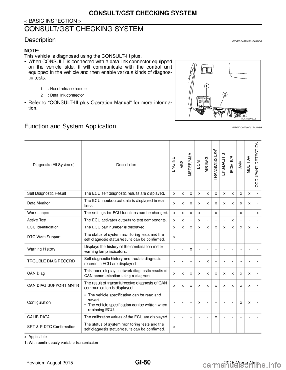
NOTE:
This vehicle is diagnosed using the CONSULT-III plus.
• When CONSULT is connected with a data link connector equippedon the vehicle side, it will communicate with the control unit
equipped in the vehicle and then enable various kinds of diagnos-
tic tests.
• Refer to “CONSULT-III plus Operation Manual” for more informa- tion.
Function and System ApplicationINFOID:0000000012433189
x: Applicable
1: With continuously variable transmission 1 : Hood release handle
2 : Data link connector
ALAIA0095ZZ
Diagnosis (All Systems)
Description
ENGINE
ABS
METER/M&A BCM
AIR BAG
TRANSMISSION
1
EPS/DAST 3 IPDM E/R AV M
MULTI AV
OCCUPANT DETECTION
Self Diagnostic Result The ECU self diagnostic results are displayed. x x x x x x x x x x -
Data Monitor The ECU input/output data is displayed in real
time. xxxxxxxxxx -
Work support The settings for ECU functions can be changed. x x x x - x - - x - x
Active Test The ECU activates outputs to test components. x x - x - - - x - - -
ECU identification The ECU part number is displayed. xxxxxxxxxx -
DTC Work Support The status of system monitoring tests and the
self diagnosis status/results can be confirmed. x----------
Warning History Displays the history of the combination meter
warning lamp indicators.
--x--------
TROUBLE DIAG RECORD Self diagnostic history and trouble diagnosis
records in ECU are displayed. ----x------
CAN Diag This mode displays network diagnostic results of
CAN communication using a diagram. xxxxxxxxxx -
CAN DIAG SUPPORT MNTR The result of transmit/receive diagnosis of CAN
communication is displayed.
xxxxxxxxxx -
Configuration • The vehicle specification can be read and
saved.
• The vehicle specification can be written when
replacing ECU. ---x----xx-
CALIB DATA The calibration values of the ECU are displayed. - - - - - x - - - - -
SRT & P-DTC Confirmation The status of system monitoring tests and the
self diagnosis status/results can be confirmed. x----------
Revision: August 2015
2016 Versa Note
cardiagn.com
Page 1942 of 3641

GW-2
< PRECAUTION >
PRECAUTIONS
PRECAUTION
PRECAUTIONS
Precaution for Supplemental Restraint System (SRS) "AIR BAG" and "SEAT BELT
PRE-TENSIONER"
INFOID:0000000012430522
The Supplemental Restraint System such as “A IR BAG” and “SEAT BELT PRE-TENSIONER”, used along
with a front seat belt, helps to reduce the risk or severity of injury to the driver and front passenger for certain
types of collision. Information necessary to service the system safely is included in the SR and SB section of
this Service Manual.
WARNING:
• To avoid rendering the SRS inopera tive, which could increase the risk of personal injury or death in
the event of a collision which would result in air bag inflation, all maintenance must be performed by
an authorized NISSAN/INFINITI dealer.
• Improper maintenance, including in correct removal and installation of the SRS, can lead to personal
injury caused by unintent ional activation of the system. For re moval of Spiral Cable and Air Bag
Module, see the SR section.
• Do not use electrical test equipmen t on any circuit related to the SRS unless instructed to in this
Service Manual. SRS wiring harn esses can be identified by yellow and/or orange harnesses or har-
ness connectors.
PRECAUTIONS WHEN USING POWER TOOLS (AIR OR ELECTRIC) AND HAMMERS
WARNING:
• When working near the Airbag Diagnosis Sensor Unit or other Airbag System sensors with the Igni-
tion ON or engine running, DO NOT use air or electri c power tools or strike near the sensor(s) with a
hammer. Heavy vibration could activate the sensor( s) and deploy the air bag(s), possibly causing
serious injury.
• When using air or electric power tools or hammers , always switch the Ignition OFF, disconnect the
battery and wait at least three minutes before performing any service.
Handling for Adhe sive and PrimerINFOID:0000000012430523
• Do not use an adhesive which is past its usable date. Shel f life of this product is limited to six months after
the date of manufacture. Carefully adhere to the expiration or manufacture date printed on the box.
• Keep primers and adhesive in a cool, dry place. Ideally, they should be stored in a refrigerator.
• Open the seal of the primer and adhesive just before application. Discard the remainder.
• Before application, be sure to shake the primer container to stir the contents. If any floating material is found,
do not use it.
• If any primer or adhesive contacts the skin, wipe it off with gasoline or equivalent and wash the skin with
soap.
• When using primer and adhesive, always observe the precautions in the instruction manual.
Precaution for WorkINFOID:0000000012430524
• When removing or disassembling each component, be careful not to damage or deform it. If a component
may be subject to interference, be sure to protect it with a shop cloth.
• When removing (disengaging) components with a screwdriver or similar tool, be sure to wrap the component with a shop cloth or vinyl tape to protect it.
• Protect the removed parts with a shop cloth and prevent them from being dropped.
• Replace a deformed or damaged clip.
• If a part is specified as a non-reusable part, always replace it with a new one.
• Be sure to tighten bolts and nuts securely to the specified torque.
• After installation is complete, be sure to check that each part works properly.
• Follow the steps below to clean components:
- Water soluble dirt:
• Dip a soft cloth into lukewarm water, wring the water out of the cloth and wipe the dirty area.
• Then rub with a soft, dry cloth.
- Oily dirt:
• Dip a soft cloth into lukewarm water with mild detergent (concentration: within 2 to 3%) and wipe the dirty area.
Revision: August 2015 2016 Versa Note
cardiagn.com
Page 1944 of 3641
GW-4
< PREPARATION >
PREPARATION
PREPARATION
PREPARATION
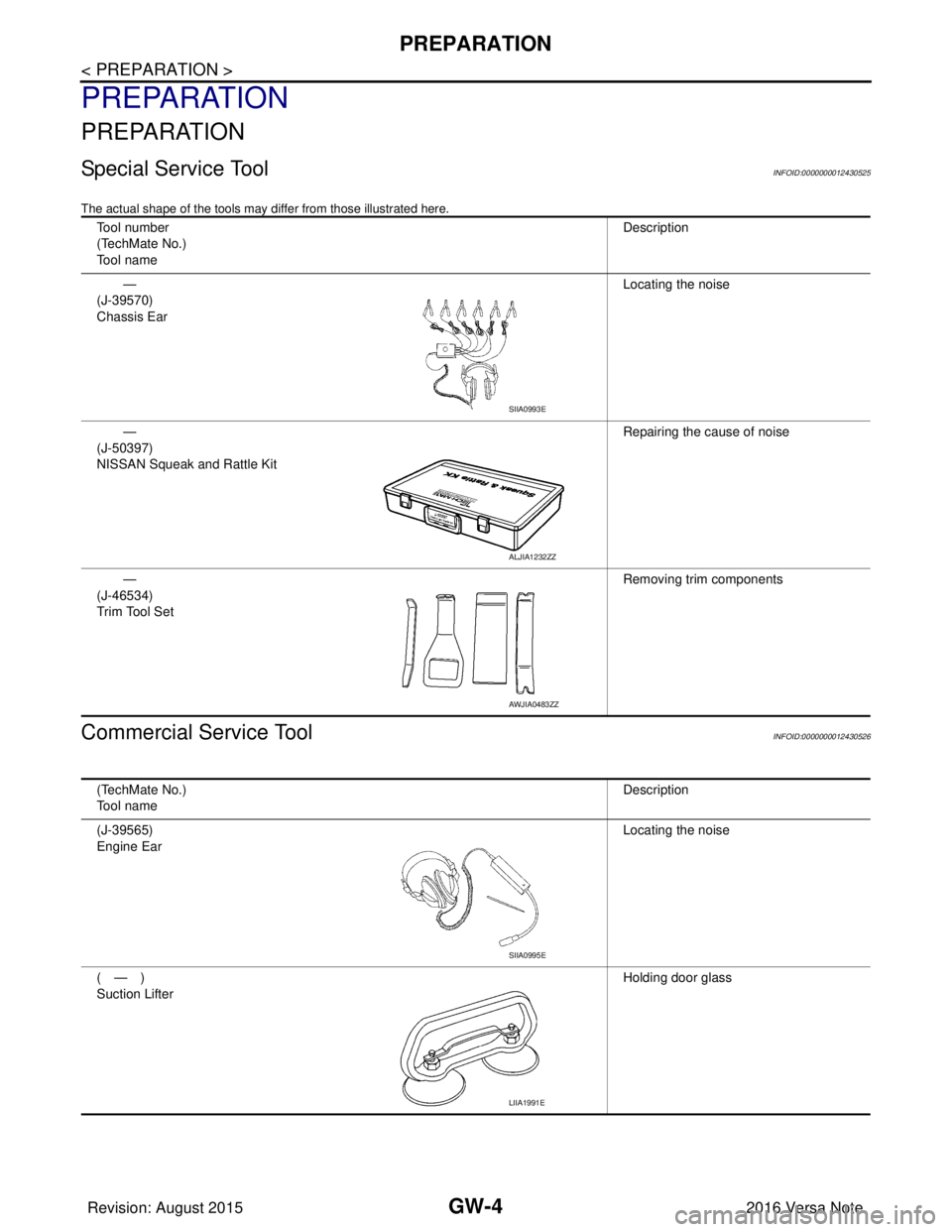
Special Service ToolINFOID:0000000012430525
The actual shape of the tools may differ from those illustrated here.
Commercial Service ToolINFOID:0000000012430526
Tool number
(TechMate No.)
Tool nameDescription
—
(J-39570)
Chassis Ear Locating the noise
—
(J-50397)
NISSAN Squeak and Rattle Kit Repairing the cause of noise
—
(J-46534)
Trim Tool Set Removing trim components
SIIA0993E
ALJIA1232ZZ
AWJIA0483ZZ
(TechMate No.)
Tool name
Description
(J-39565)
Engine Ear Locating the noise
(—)
Suction Lifter Holding door glass
SIIA0995E
LIIA1991E
Revision: August 2015
2016 Versa Note
cardiagn.com