2016 NISSAN NOTE engine
[x] Cancel search: enginePage 3533 of 3641

WCS-18
< SYSTEM DESCRIPTION >
DIAGNOSIS SYSTEM (COMBINATION METER)
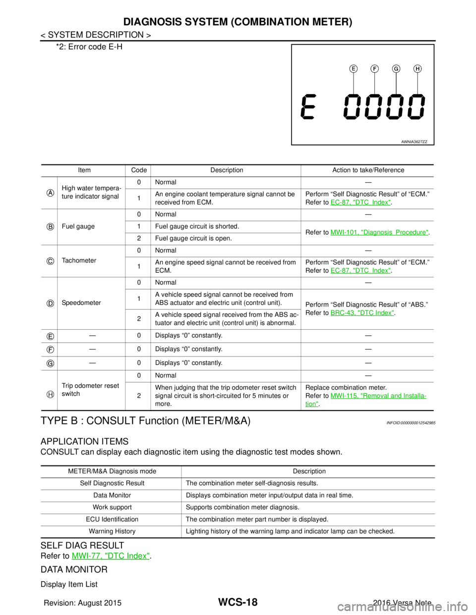
*2: Error code E-H
TYPE B : CONSULT Function (METER/M&A)INFOID:0000000012542985
APPLICATION ITEMS
CONSULT can display each diagnostic item using the diagnostic test modes shown.
SELF DIAG RESULT
Refer to MWI-77, "DTC Index".
DATA MONITOR
Display Item List
AWNIA3627ZZ
Item Code Description Action to take/Reference
High water tempera-
ture indicator signal 0Normal
—
1 An engine coolant temperature signal cannot be
received from ECM. Perform “Self Diagnostic Result” of “ECM.”
Refer to
EC-87, "
DTCIndex".
Fuel gauge 0Normal
—
1 Fuel gauge circuit is shorted. Refer to MWI-101, "
DiagnosisProcedure".
2 Fuel gauge circuit is open.
Tachometer 0Normal
—
1 An engine speed signal cannot be received from
ECM. Perform “Self Diagnostic Result” of “ECM.”
Refer to
EC-87, "
DTCIndex".
Speedometer 0Normal
—
1 A vehicle speed signal cannot be received from
ABS actuator and electric unit (control unit).
Perform “Self Diagnostic Result” of “ABS.”
Refer to BRC-43, "
DTC Index".
2 A vehicle speed signal re
ceived from the ABS ac-
tuator and electric unit (control unit) is abnormal.
— 0 Displays “0” constantly. —
— 0 Displays “0” constantly. —
— 0 Displays “0” constantly. —
Trip odometer reset
switch 0Normal
—
2 When judging that the trip odometer reset switch
signal circuit is short-circuited for 5 minutes or
more. Replace combination meter.
Refer to
MWI-115, "
Removal and Installa-
tion".
METER/M&A Diagnosis mode Description
Self Diagnostic Result The combination meter self-diagnosis results.
Data Monitor Displays combination meter input/output data in real time.
Work support Supports combination meter diagnosis.
ECU Identification The combination meter part number is displayed.
Warning History Lighting history of the warning lamp and indicator lamp can be checked.
Revision: August 2015 2016 Versa Note
cardiagn.com
Page 3534 of 3641
![NISSAN NOTE 2016 Service Repair Manual WCS
DIAGNOSIS SYSTEM (COMBINATION METER)WCS-19
< SYSTEM DESCRIPTION >
C
DE
F
G H
I
J
K L
M B A
O P
X: Applicable
Display item [Unit] MAIN
SIGNALS Description
SPEED METER
[mph] or [km/h] X Displays the NISSAN NOTE 2016 Service Repair Manual WCS
DIAGNOSIS SYSTEM (COMBINATION METER)WCS-19
< SYSTEM DESCRIPTION >
C
DE
F
G H
I
J
K L
M B A
O P
X: Applicable
Display item [Unit] MAIN
SIGNALS Description
SPEED METER
[mph] or [km/h] X Displays the](/manual-img/5/57363/w960_57363-3533.png)
WCS
DIAGNOSIS SYSTEM (COMBINATION METER)WCS-19
< SYSTEM DESCRIPTION >
C
DE
F
G H
I
J
K L
M B A
O P
X: Applicable
Display item [Unit] MAIN
SIGNALS Description
SPEED METER
[mph] or [km/h] X Displays the value of vehicle speed signal.
SPEED OUTPUT
[mph] or [km/h] X
Displays the value of vehicle speed signal, which is transmitted to each unit with
CAN communication.
ODO OUTPUT
[mph] or [km/h] Displays odometer signal value transmitted to other units via CAN communica-
tion.
TACHO METER
[rpm] X Displays the value of engine speed signal, which is input from ECM.
FUEL METER
[L] X Displays the fuel level.
W TEMP METER
[ ° C] or [ °F] X Displays the value of engine coolant temperature signal, which is input from ECM.
ABS W/L
[On/Off] Displays [ON/OFF] condition of ABS warning indicator
VDC/TCS IND
[ON/OFF] Displays [ON/OFF] condition of VDC OFF indicator lamp.
SLIP IND
[ON/OFF] Displays [ON/OFF] condition of SLIP indicator lamp.
BRAKE W/L
[On/Off] Displays [ON/OFF] condition of brake warning indicator.
DOOR W/L
[On/Off] Displays [ON/OFF] condition of door warning indicator.
HI-BEAM IND
[On/Off] Displays [ON/OFF] condition of high beam indicator.
TURN IND
[On/Off] Displays [ON/OFF] condition of turn indicator.
LIGHT IND
[On/Off] Displays [ON/OFF] condition of light indicator.
OIL W/L
[On/Off] Displays [ON/OFF] condition of engine oil pressure warning indicator.
MIL
[On/Off] Displays [ON/OFF] condition of malfunction indicator.
CRUISE IND
[Off] Displays [ON/OFF] cond
ition of CRUISE indicator.
O/D OFF IND
[On/Off] Displays [ON/OFF] condition of O/D OFF indicator.
FUEL W/L
[On/Off] Displays [ON/OFF] condition of low-fuel warning indicator.
PASS BUCKLE SW
[On/Off] Status of seat belt buckle switch RH.
AIR PRES W/L
[ON/OFF] Displays [ON/OFF] condition of tire pressure warning lamp.
KEY G/Y W/L
[ON/OFF] Displays [ON/OFF] condition of key warning lamp.
EPS W/L
[On/Off] Displays [ON/OFF] condition of EPS indicator.
FUEL CAP W/L
[Off] Displays [ON/OFF] condition of loose fuel cap warning message.
PKB SW
[On/Off] Status of parking brake switch.
Revision: August 2015
2016 Versa Note
cardiagn.com
Page 3535 of 3641

WCS-20
< SYSTEM DESCRIPTION >
DIAGNOSIS SYSTEM (COMBINATION METER)
NOTE:
Some items are not available according to vehicle specification.
WORK SUPPORT
WARNING HISTORY
W/L ON HISTORY
• Stores histories when warning/indicator lamp is turned on.
• “W/L ON HISTORY” indicates the “TIME” when the warning/ indicator lamp is turned on.
• The “TIME” above is:
- 0: The condition that the warning/indicator lamp has been turned on 1 or more times after starting the engine and waiting for 30 seconds.
- 1 - 39: The number of times the engine was restarted after the 0 condition.
- NO W/L ON HISTORY: Stores NO (0) turning on history of warning/indicator lamp.
NOTE:
• W/L ON HISTORY is not stored for approximately 30 seconds after the engine starts.
• Brake warning lamp does not store any history when the parking brake is applied or the brake fluid level gets low.
BUCKLE SW
[On/Off] Status of seat belt buckle switch (LH).
BRAKE OIL SW
[On/Off] Status of brake fluid level switch.
CHG SIG
[On/Off] Displays [ON/OFF] condition of charge warning indicator.
DISTANCE
[km] or [Mi] Displays distance to empty.
OUTSIDE TEMP
[ ° F] or [ °C] Displays the ambient temperature, which is input from ambient sensor.
FUEL LOW SIG
[ON/OFF] Displays [ON/OFF] condition
of low-fuel warning signal.
BUZZER
[On/Off] X Displays [ON/OFF] condition of buzzer.
FR FOG IND
[On/Off] Displays [ON/OFF] condition of front fog lamp indicator.
TPMS PRESS L
[On/Off] Displays [ON/OFF] condition of check tire pressure warning message.
Display item [Unit]
MAIN
SIGNALS Description
Work support item
Description
Outside air temperature diagnosis A possible malfunction can be narrowed down by following the displayed instructions.
Fuel meter diagnosis(Analog pointer)
Warning lamp diagnosis
Display item Description
W/L ON HISTORY Lighting history of warning lamp and indicator lamp can be checked.
Revision: August 2015 2016 Versa Note
cardiagn.com
Page 3562 of 3641

WCS
THE PARKING BRAKE RELEASE WARNING CONTINUES SOUNDING, OR
DOES NOT SOUND
WCS-47
< SYMPTOM DIAGNOSIS >
C
DE
F
G H
I
J
K L
M B A
O P
SYMPTOM DIAGNOSIS
THE PARKING BRAKE RELEASE WARN ING CONTINUES SOUNDING, OR
DOES NOT SOUND
DescriptionINFOID:0000000012432710
• The parking brake warning buzzer sounds continuously during vehicle travel though the parking brake is
released.
• The parking brake warning buzzer does not sound at all even though driving the vehicle with the parking brake applied.
Diagnosis ProcedureINFOID:0000000012432711
NOTE:
To identify combination meter type, refer to WCS-3, "
Information".
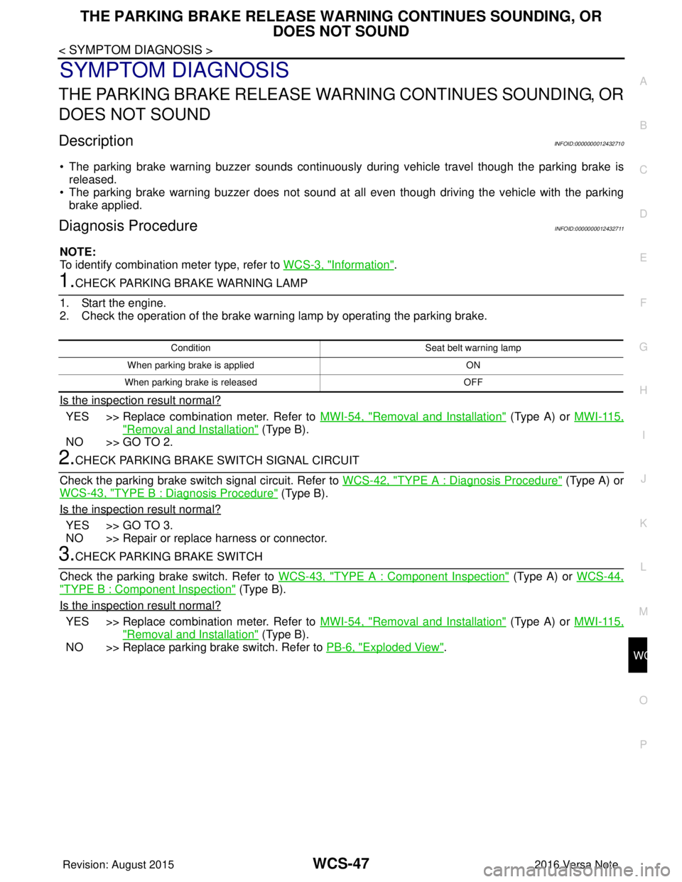
1.CHECK PARKING BRAKE WARNING LAMP
1. Start the engine.
2. Check the operation of the brake warning lamp by operating the parking brake.
Is the inspection result normal?
YES >> Replace combination meter. Refer to MWI-54, "Removal and Installation" (Type A) or MWI-115,
"Removal and Installation" (Type B).
NO >> GO TO 2.
2.CHECK PARKING BRAKE SWITCH SIGNAL CIRCUIT
Check the parking brake switch signal circuit. Refer to WCS-42, "
TYPE A : Diagnosis Procedure" (Type A) or
WCS-43, "
TYPE B : Diagnosis Procedure" (Type B).
Is the inspection result normal?
YES >> GO TO 3.
NO >> Repair or replace harness or connector.
3.CHECK PARKING BRAKE SWITCH
Check the parking brake switch. Refer to WCS-43, "
TYPE A : Component Inspection" (Type A) or WCS-44,
"TYPE B : Component Inspection" (Type B).
Is the inspection result normal?
YES >> Replace combination meter. Refer to MWI-54, "Removal and Installation" (Type A) or MWI-115,
"Removal and Installation" (Type B).
NO >> Replace parking brake switch. Refer to PB-6, "
Exploded View".
Condition Seat belt warning lamp
When parking brake is applied ON
When parking brake is released OFF
Revision: August 2015 2016 Versa Note
cardiagn.com
Page 3568 of 3641

PRECAUTIONSWW-3
< PRECAUTION >
C
DE
F
G H
I
J
K
M A
B
WW
N
O P
PRECAUTION
PRECAUTIONS
Precaution for Supplemental Restraint System (SRS) "AIR BAG" and "SEAT BELT
PRE-TENSIONER"
INFOID:0000000012433192
The Supplemental Restraint System such as “AIR BAG” and “SEAT BELT PRE-TENSIONER”, used along
with a front seat belt, helps to reduce the risk or severi ty of injury to the driver and front passenger for certain
types of collision. Information necessary to service the system safely is included in the SR and SB section of
this Service Manual.
WARNING:
• To avoid rendering the SRS inoper ative, which could increase the risk of personal injury or death in
the event of a collision which would result in air bag inflation, all maintenance must be performed by
an authorized NISSAN/INFINITI dealer.
• Improper maintenance, including in correct removal and installation of the SRS, can lead to personal
injury caused by unintentional act ivation of the system. For removal of Spiral Cable and Air Bag
Module, see the SR section.
• Do not use electrical test equipm ent on any circuit related to the SRS unless instructed to in this
Service Manual. SRS wiring harnesses can be identi fied by yellow and/or orange harnesses or har-
ness connectors.
PRECAUTIONS WHEN USING POWER TOOLS (AIR OR ELECTRIC) AND HAMMERS
WARNING:
• When working near the Airbag Diagnosis Sensor Un it or other Airbag System sensors with the Igni-
tion ON or engine running, DO NOT use air or el ectric power tools or strike near the sensor(s) with a
hammer. Heavy vibration could activate the sensor( s) and deploy the air bag(s), possibly causing
serious injury.
• When using air or electric power tools or hammers, always switch the Ignition OFF, disconnect the
battery and wait at least three mi nutes before performing any service.
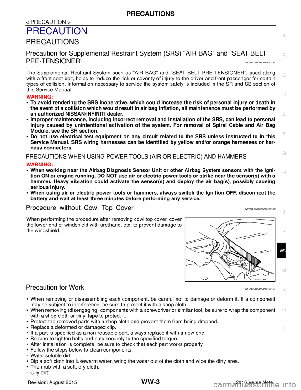
Procedure without Cowl Top CoverINFOID:0000000012433193
When performing the procedure after removing cowl top cover, cover
the lower end of windshield with urethane, etc. to prevent damage to
the windshield.
Precaution for WorkINFOID:0000000012433194
• When removing or disassembling each component, be ca reful not to damage or deform it. If a component
may be subject to interference, be sure to protect it with a shop cloth.
• When removing (disengaging) components with a screwdriver or similar tool, be sure to wrap the component with a shop cloth or vinyl tape to protect it.
• Protect the removed parts with a shop cloth and prevent them from being dropped.
• Replace a deformed or damaged clip.
• If a part is specified as a non-reusabl e part, always replace it with a new one.
• Be sure to tighten bolts and nuts securely to the specified torque.
• After installation is complete, be sure to check that each part works properly.
• Follow the steps below to clean components:
- Water soluble dirt:
• Dip a soft cloth into lukewarm water, wring the water out of the cloth and wipe the dirty area.
• Then rub with a soft, dry cloth.
-Oily dirt:
PIIB3706J
Revision: August 2015 2016 Versa Note
cardiagn.com
Page 3571 of 3641

WW-6
< SYSTEM DESCRIPTION >
COMPONENT PARTS
SYSTEM DESCRIPTION
COMPONENT PARTS
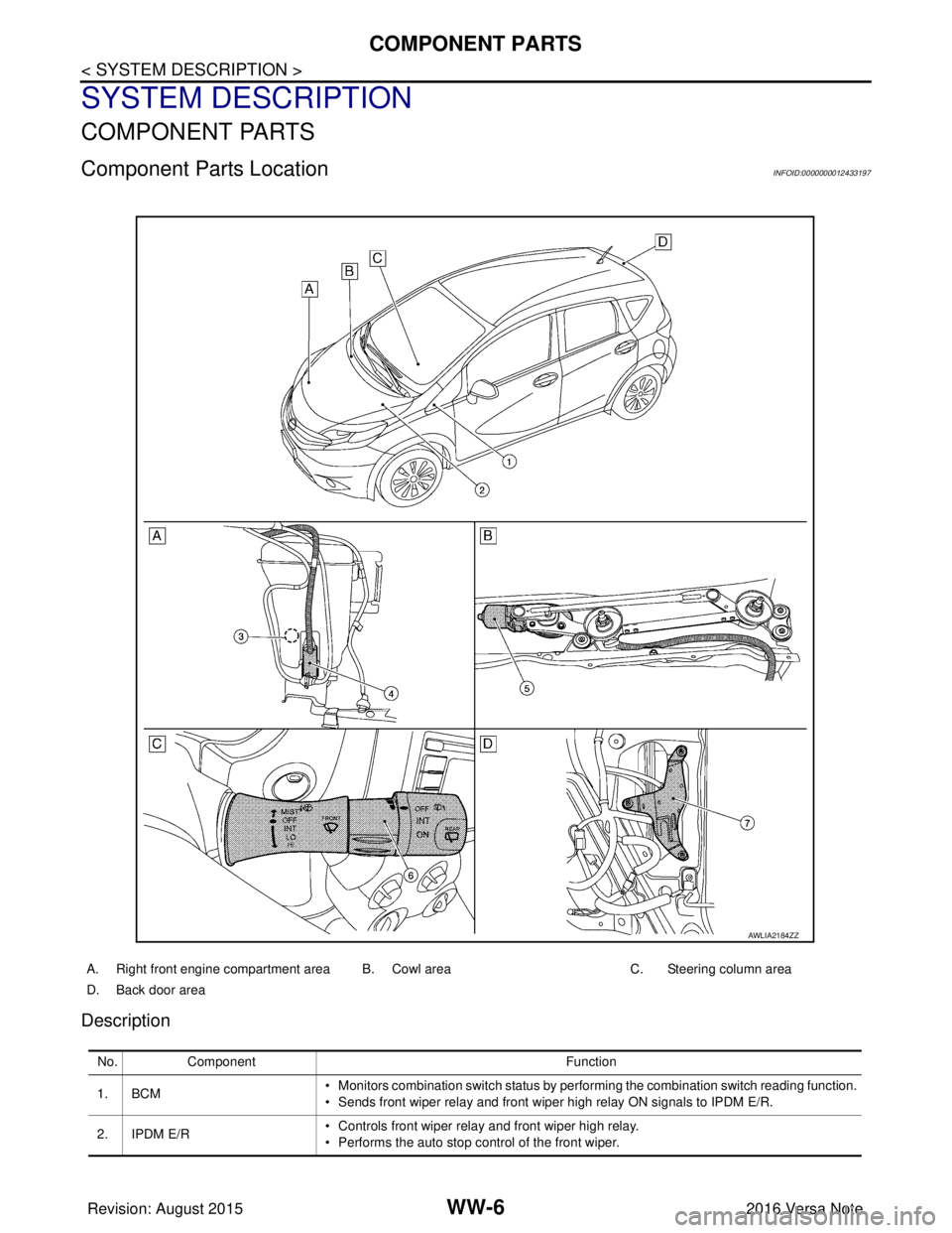
Component Parts LocationINFOID:0000000012433197
Description
A. Right front engine compartment area B. Cowl areaC. Steering column area
D. Back door area
AWLIA2184ZZ
No. Component Function
1. BCM • Monitors combination switch status by performing the combination switch reading function.
• Sends front wiper relay and front wiper high relay ON signals to IPDM E/R.
2. IPDM E/R • Controls front wiper relay and front wiper high relay.
• Performs the auto stop control of the front wiper.
Revision: August 2015
2016 Versa Note
cardiagn.com