2016 NISSAN NOTE engine
[x] Cancel search: enginePage 1661 of 3641
SYSTEMEXL-9
< SYSTEM DESCRIPTION >
C
DE
F
G H
I
J
K
M A
B
EXL
N
O P
Under this condition, the headlamps remain illuminated for 45 seconds unless the lighting switch position is
changed. If the lighting switch position is changed, then the headlamps are turned off.
This setting can be changed by CONSULT. Refer to BCS-20, "
HEADLAMP : CONSULT Function (BCM -
HEAD LAMP)" (with Intelligent Key system) or BCS-93, "HEADLAMP : CONSULT Function (BCM - HEAD
LAMP)" (without Intelligent Key system).
DAYTIME RUNNING LIGHT SYSTEM
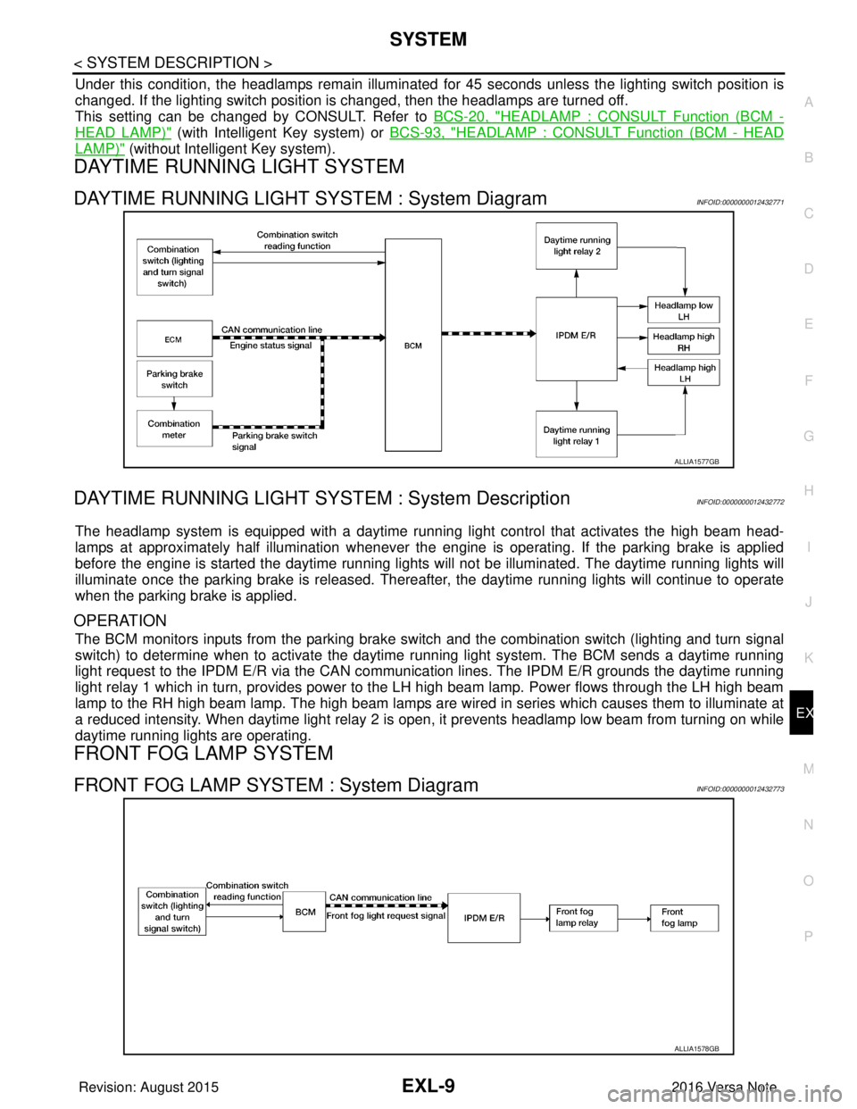
DAYTIME RUNNING LIGHT SYSTEM : System DiagramINFOID:0000000012432771
DAYTIME RUNNING LIGHT SYST EM : System DescriptionINFOID:0000000012432772
The headlamp system is equipped with a daytime running light control that activates the high beam head-
lamps at approximately half illumination whenever the e ngine is operating. If the parking brake is applied
before the engine is started the daytime running lights will not be illuminated. The daytime running lights will
illuminate once the parking brake is released. Thereaf ter, the daytime running lights will continue to operate
when the parking brake is applied.
OPERATION
The BCM monitors inputs from the parking brake swit ch and the combination switch (lighting and turn signal
switch) to determine when to activate the daytime running light system. The BCM sends a daytime running
light request to the IPDM E/R via the CAN communication lines. The IPDM E/R grounds the daytime running
light relay 1 which in turn, provides power to the LH high beam lamp. Power flows through the LH high beam
lamp to the RH high beam lamp. The high beam lamps are wired in series which causes them to illuminate at
a reduced intensity. When daytime light relay 2 is open, it prevents headlamp low beam from turning on while
daytime running lights are operating.
FRONT FOG LAMP SYSTEM
FRONT FOG LAMP SYSTEM : System DiagramINFOID:0000000012432773
ALLIA1577GB
ALLIA1578GB
Revision: August 2015 2016 Versa Note
cardiagn.com
Page 1665 of 3641

DIAGNOSIS SYSTEM (BCM) (WITH INTELLIGENT KEY SYSTEM)
EXL-13
< SYSTEM DESCRIPTION >
C
D E
F
G H
I
J
K
M A
B
EXL
N
O P
HEADLAMP
HEADLAMP : CONSULT Function (BCM - HEAD LAMP)INFOID:0000000012542303
DATA MONITOR
ACTIVE TEST
WORK SUPPORT
*: Initial setting
FLASHER
Monitor Item [Unit] Description
PUSH SW [On/Off] Indicates condition of push-button ignition switch.
ENGINE STATE [Stop/Stall/Crank/Run] Indicates engine status received from ECM on CAN communication line.
VEH SPEED 1 [km/h] Indicates vehicle speed signal received from ABS on CAN communication line.
TURN SIGNAL R [On/Off]
Indicates condition of combination switch.
TURN SIGNAL L [On/Off]
TAIL LAMP SW [On/Off]
HI BEAM SW [On/Off]
HEAD LAMP SW 1 [On/Off]
HEAD LAMP SW 2 [On/Off]
PASSING SW [On/Off]
FR FOG SW [On/Off]
DOOR SW-DR [On/Off]
Indicates condition of front door switch LH.
DOOR SW-AS [On/Off] Indicates condition of front door switch RH.
DOOR SW-RR [On/Off] Indicates condition of rear door switch RH.
DOOR SW-RL [On/Off] Indicates condition of rear door switch LH.
DOOR SW-BK [On/Off] Indicates condition of back door switch.
Test Item Description
FR FOG LAMP This test is able to check front fog lamp operation [On/Off].
HEAD LAMP This test is able to check head lamp operation [Hi/Low/Off].
ILL DIM SIGNAL This test is able to check head lamp illumination dimming operation [On/Off].
TAIL LAMP This test is able to check tail lamp operation [On/Off].
Support ItemSetting Description
BATTERY SAVER SET On*
Exterior lamp battery saver function ON.
Off Exterior lamp battery saver function OFF.
ILL DELAY SET MODE 8 180 sec.
Sets delay timer function operation time
(All doors closed).
MODE 7 150 sec.
MODE 6 120 sec.
MODE 4 60 sec.
MODE 5 90 sec.
MODE 3 30 sec.
MODE 2 OFF
MODE 1* 45 sec.
Revision: August 2015
2016 Versa Note
cardiagn.com
Page 1669 of 3641

DIAGNOSIS SYSTEM (BCM) (WITHOUT INTELLIGENT KEY SYSTEM)EXL-17
< SYSTEM DESCRIPTION >
C
DE
F
G H
I
J
K
M A
B
EXL
N
O P
HEADLAMP
HEADLAMP : CONSULT Function (BCM - HEAD LAMP)INFOID:0000000012542312
DATA MONITOR
ACTIVE TEST
WORK SUPPORT
* : Initial setting
FLASHER
FLASHER : CONSULT Func tion (BCM - FLASHER)INFOID:0000000012542313
DATA MONITOR
Monitor Item [Unit] Description
IGN ON SW [On/Off] Indicates condition of ignition switch ON position.
ACC ON SW [On/Off] Indicates condition of ignition switch ACC position.
HI BEAM SW [On/Off]
Indicates condition of combination switch.
HEAD LAMP SW 1 [On/Off]
HEAD LAMP SW 2 [On/Off]
TAIL LAMP SW [On/Off]
PASSING SW [On/Off]
FR FOG SW [On/Off]
DOOR SW-DR [On/Off]
Indicates condition of front door switch LH.
DOOR SW-AS [On/Off] Indicates condition of front door switch RH.
DOOR SW-RR [On/Off] Indicates condition of rear door switch RH.
DOOR SW-RL [On/Off] Indicates condition of rear door switch LH.
DOOR SW-BK [On/Off] Indicates condition of back door switch.
TURN SIGNAL R [On/Off] Indicates condition of combination switch.
TURN SIGNAL L [On/Off]
KEY ON SW [On/Off] Indicates condition of key switch.
KEYLESS LOCK [On/Off] Indicates condition of lock signal from keyfob.
PKB SW [On/Off] Indicates park brake switch signal received from combination meter on CAN communica-
tion line.
ENGINE RUN [On/Off] Indicates engine run signal receiv ed from ECM on CAN communication line.
VEHICLE SPEED [km/h/mph] Indicates vehicle speed signal received from combination meter on CAN communication
line.
Test Item
Description
TAIL LAMP This test is able to check tail lamp operation [On/Off].
HEAD LAMP This test is able to check head lamp operation [Hi/Low/Off].
FR FOG LAMP This test is able to check front fog lamp operation [On/Off].
ILL DIM SIGNAL This test is able to check head lamp illumination dimming operation [On/Off].
Support ItemSetting Description
BATTERY SAVER SET On*
Exterior lamp battery saver function ON.
Off Exterior lamp battery saver function OFF.
Revision: August 2015 2016 Versa Note
cardiagn.com
Page 1729 of 3641
HEADLAMP (HI) CIRCUITEXL-77
< DTC/CIRCUIT DIAGNOSIS >
C
DE
F
G H
I
J
K
M A
B
EXL
N
O P
HEADLAMP (HI) CIRCUIT
DescriptionINFOID:0000000012432804
The IPDM E/R (intelligent power distribution modul e engine room) controls the headlamp high relay based on
inputs from the BCM via the CAN communication lines. When the headlamp high relay is energized, power
flows through fuses 34 and 35, located in the IPDM E/R. Power then flows to the front combination lamp LH
and RH high beams.
Component Function CheckINFOID:0000000012432805
1.CHECK HEADLAMP (HI) OPERATION
WITHOUT CONSULT
1. Start IPDM E/R auto active test. Refer to PCS-9, "
Diagnosis Description".
2. Check that the headlamp switches to the high beam.
CONSULT
1. Select EXTERNAL LAMPS of IP DM E/R active test item.
2. While operating the test items, check that the headlamp switches to the high beam.
Does the headlamp switch to high beam?
YES >> Headlamp (HI) circuit is normal.
NO >> Refer to EXL-77, "
Diagnosis Procedure".
Diagnosis ProcedureINFOID:0000000012432806
Regarding Wiring Diagram information, refer to EXL-25, "Wiring Diagram - For USA" or EXL-31, "Wiring Dia-
gram - For Canada".
1.CHECK HEADLAMP (HI) FUSES
1. Turn the ignition switch OFF.
2. Check that the following fuses are not blown:
Is the fuse blown?
YES >> Replace the blown fuse after repairing the affected circuit.
NO >> GO TO 2.
2.CHECK HIGH BEAM BULB
Check the applicable high beam bulb to be sure the proper bulb standard is in use and the bulb is not open.
Is the bulb OK?
YES >> GO TO 3.
NO >> Replace the bulb.
3.CHECK HEADLAMP (HI) OUTPUT VOLTAGE
1. Turn the ignition switch OFF.
2. Disconnect the front combination lamp connector E25 or E26.
3. Turn the ignition switch ON.
4. Turn the high beam headlamps ON.
5. With the high beam headlamps ON, check the vo ltage between the combination lamp connector and
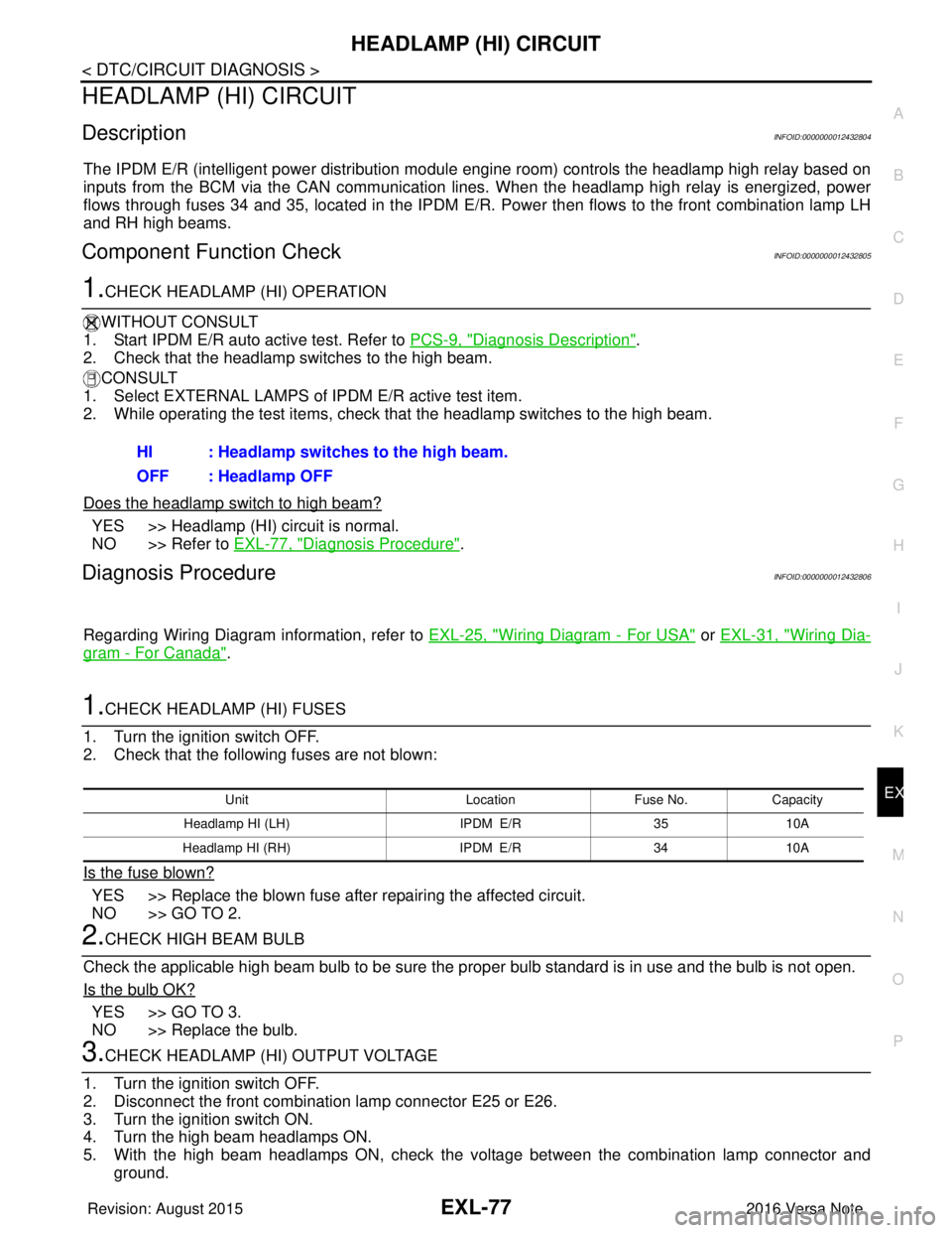
ground. HI : Headlamp switches to the high beam.
OFF : Headlamp OFF
Unit
LocationFuse No.Capacity
Headlamp HI (LH) IPDM E/R3510A
Headlamp HI (RH) IPDM E/R3410A
Revision: August 2015 2016 Versa Note
cardiagn.com
Page 1731 of 3641
HEADLAMP (LO) CIRCUITEXL-79
< DTC/CIRCUIT DIAGNOSIS >
C
DE
F
G H
I
J
K
M A
B
EXL
N
O P
HEADLAMP (LO) CIRCUIT
DescriptionINFOID:0000000012432807
The IPDM E/R (intelligent power distribution modul e engine room) controls the headlamp low relay based on
inputs from the BCM via the CAN communication li nes. When the headlamp low relay is energized, power
flows through fuses 40 and 41, located in the IPDM E/R.
(Without daytime running light system) power then flow s to the front combination lamp LH and RH low beams.
(With daytime running light system) power then flows to the front combination lamp LH low beam and the day-
time running light relay 2 which becomes energized and t hen power is sent to the front combination lamp RH
low beam.
Component Function CheckINFOID:0000000012432808
1.CHECK HEADLAMP (LO) OPERATION
WITHOUT CONSULT
1. Start IPDM E/R auto active test. Refer to PCS-9, "
Diagnosis Description".
2. Check that the headlamp is turned ON.
CONSULT
1. Select EXTERNAL LAMPS of IP DM E/R active test item.
2. While operating the test items, check that the headlamp is turned ON.
Is the headlamp turned ON?
YES >> Headlamp (LO) is normal.
NO >> Refer to EXL-79, "
Diagnosis Procedure".
Diagnosis ProcedureINFOID:0000000012432809
Regarding Wiring Diagram information, refer to EXL-25, "Wiring Diagram - For USA" or EXL-31, "Wiring Dia-
gram - For Canada".
1.CHECK HEADLAMP (LO) FUSES
1. Turn the ignition switch OFF.
2. Check that the following fuses are not blown:
Is the fuse blown?
YES >> Replace the blown fuse after repairing the affected circuit.
NO >> GO TO 2.
2.CHECK LOW BEAM BULB
Check the applicable low beam bulb to be sure the proper bulb standard is in use and the bulb is not open.
Is the bulb OK?
YES >> GO TO 3.
NO >> Replace the bulb.
3.CHECK HEADLAMP (LO) OUTPUT VOLTAGE
1. Turn the ignition switch OFF.
2. Disconnect the front combination lamp connector E25 or E26.
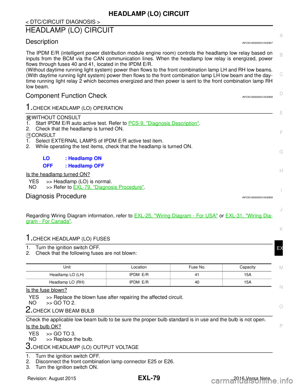
3. Turn the ignition switch ON. LO : Headlamp ON
OFF : Headlamp OFF
Unit
LocationFuse No.Capacity
Headlamp LO (L H) IPDM E/R 4115A
Headlamp LO (RH) IPDM E/R4015A
Revision: August 2015 2016 Versa Note
cardiagn.com
Page 1734 of 3641
EXL-82
< DTC/CIRCUIT DIAGNOSIS >
PARKING LAMP CIRCUIT
PARKING LAMP CIRCUIT
DescriptionINFOID:0000000012432810
The IPDM E/R (intelligent power distribution module engine room) controls the tail lamp relay based on inputs
from the BCM via the CAN communication lines. When the tail lamp relay is energized, power flows through
fuse 37, located in the IPDM E/R. Power then flows through the tail lamp relay to the front and rear combina-
tion lamps, license plate lamps.
Component Function CheckINFOID:0000000012432811
1.CHECK PARKING LAMP OPERATION
WITHOUT CONSULT
1. Start IPDM E/R auto active test. Refer to PCS-9, "
Diagnosis Description".
2. Check that the parking lamps are turned ON.
CONSULT
1. Select EXTERNAL LAMPS of IPDM E/R active test item.
2. While operating the test items, check that the parking lamps are turned ON.
Is the parking lamp turned ON?
YES >> Parking lamp circuit is normal.
NO >> Refer to EXL-82, "
Diagnosis Procedure".
Diagnosis ProcedureINFOID:0000000012432812
Regarding Wiring Diagram information, refer to EXL-55, "Wiring Diagram".
1.CHECK PARKING LAMP FUSES
1. Turn the ignition switch OFF.
2. Check that the following fuses are not blown:
Is the fuse blown?
YES >> Replace the blown fuse after repairing the affected circuit.
NO >> GO TO 2.
2.CHECK PARKING LAMP BULB
Check the applicable lamp bulb to be sure the proper bulb standard is in use and the bulb is not open.
Is the bulb OK?
YES >> GO TO 3.
NO >> Replace the bulb.
3.CHECK TAIL LAMP RELAY OUTPUT (VOLTAGE)
1. Turn the ignition switch OFF.
2. Disconnect the front combination lamp connector, rear combination lamp connector and license plate
lamp connector.
3. Turn the ignition switch ON.
4. Turn the parking lamps ON.
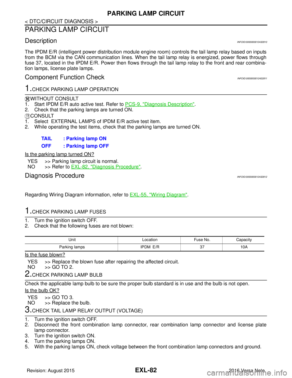
5. With the parking lamps ON, check voltage between the front combination lamp connectors and ground. TAIL : Parking lamp ON
OFF : Parking lamp OFF
Unit
LocationFuse No.Capacity
Parking lamps IPDM E/R3710A
Revision: August 2015 2016 Versa Note
cardiagn.com
Page 1749 of 3641
HEADLAMP AIMING ADJUSTMENTEXL-97
< PERIODIC MAINTENANCE >
C
DE
F
G H
I
J
K
M A
B
EXL
N
O P
PERIODIC MAINTENANCE
HEADLAMP AIMING ADJUSTMENT
InspectionINFOID:0000000012432828
PREPARATION BEFORE ADJUSTING
Before performing aiming adjustment, check the following:
• Ensure all tires are inflated to correct pressure.
• Place vehicle and screen on level surface.
• Ensure there is no load in vehicle other than the driver (or equivalent weight placed in driver's position).
• Coolant and engine oil filled to correct level, and fuel tank full.
• Remove cargo and/or luggage to maintain an unloaded vehicle condition.
• Confirm spare tire, jack and tools are properly stowed.
• Carefully wipe off any dirt from headlamp lens. CAUTION:
Do not use organic solvent (thinner, gasoline etc.)
• Place a driver or equivalent weight of 68.5 kg (150 lb) on the driver seat.
• By hand, bounce the front and rear of the vehicle to settle the suspension and eliminate any static load.
• Place the front tires in the straight ahead position.
• Confirm headlamp aiming switch is set to "0" (zero) position.
• Aim each headlamp individually and ensure other headlamp beam pattern is blocked from screen.
NOTE:
• For headlamp aiming details, refer to regulations in your area.
• By regulation, no means for horizontal aim adjustment is provided from the factory; only vertical aim is
adjustable.
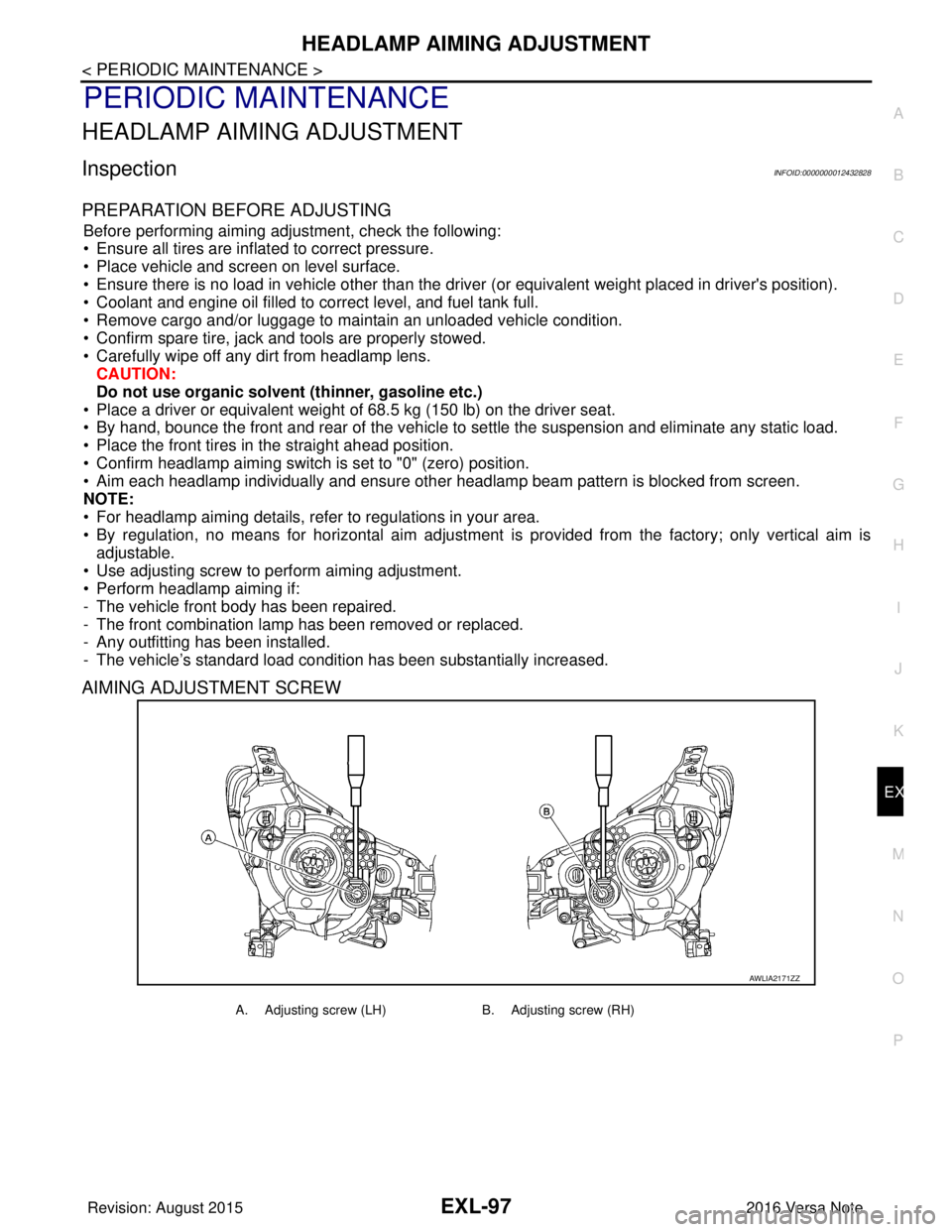
• Use adjusting screw to perform aiming adjustment.
• Perform headlamp aiming if:
- The vehicle front body has been repaired.
- The front combination lamp has been removed or replaced.
- Any outfitting has been installed.
- The vehicle’s standard load condition has been substantially increased.
AIMING ADJUSTMENT SCREW
AWLIA2171ZZ
A. Adjusting screw (LH) B. Adjusting screw (RH)
Revision: August 2015 2016 Versa Note
cardiagn.com
Page 1750 of 3641
EXL-98
< PERIODIC MAINTENANCE >
HEADLAMP AIMING ADJUSTMENT
Aiming Adjustment Procedure
INFOID:0000000012432829
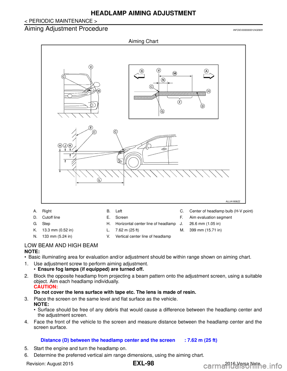
Aiming Chart
LOW BEAM AND HIGH BEAM
NOTE:
• Basic illuminating area for evaluation and/or adjus tment should be within range shown on aiming chart.
1. Use adjustment screw to perform aiming adjustment. •Ensure fog lamps (if eq uipped) are turned off.
2. Block the opposite headlamp from projecting a beam pa ttern onto the adjustment screen, using a suitable
object. Aim each headlamp individually.
CAUTION:
Do not cover the lens surface with tape etc. The lens is made of resin.
3. Place the screen on the same level and flat surface as the vehicle. NOTE:
• Surface should be free of any debris that would cause a difference between the headlamp center and
the adjustment screen.
4. Face the front of the vehicle to the screen and measure distance between the headlamp center and the screen surface.
5. Start the engine and turn the headlamp on.
6. Determine the preferred vertical aim range dimensions, using the aiming chart.
ALLIA1808ZZ
A. Right B. LeftC. Center of headlamp bulb (H-V point)
D. Cutoff line E. ScreenF. Aim evaluation segment
G. Step H. Horizontal center line of headlamp J. 26.6 mm (1.05 in)
K. 13.3 mm (0.52 in) L. 7.62 m (25 ft)M. 399 mm (15.71 in)
N. 133 mm (5.24 in) V. Vertical center line of headlamp
Distance (D) between the headlamp center and the screen : 7.62 m (25 ft)
Revision: August 2015 2016 Versa Note
cardiagn.com