2016 NISSAN NOTE suspension
[x] Cancel search: suspensionPage 2736 of 3641
RSU-8
< REMOVAL AND INSTALLATION >
REAR SHOCK ABSORBER
REMOVAL AND INSTALLATION
REAR SHOCK ABSORBER
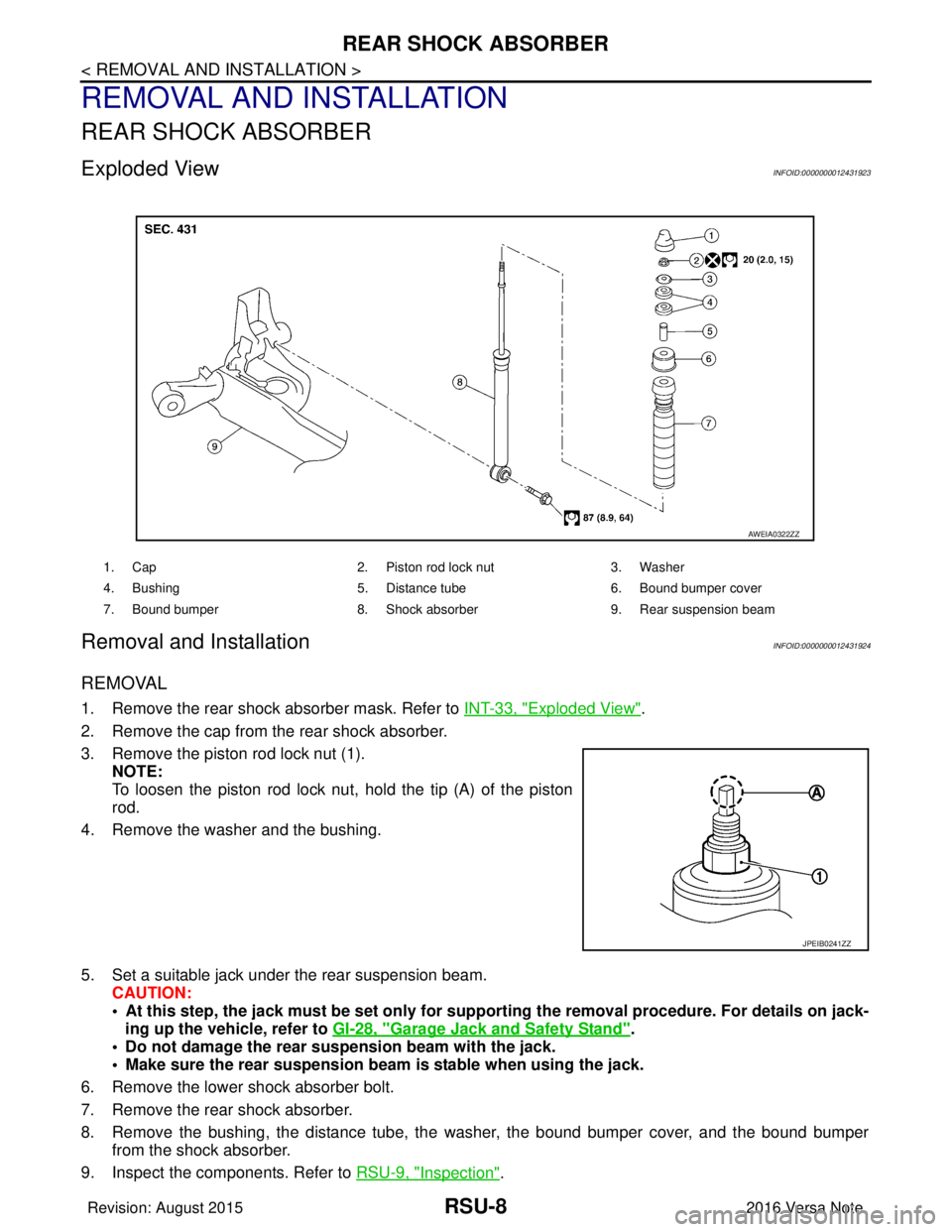
Exploded ViewINFOID:0000000012431923
Removal and InstallationINFOID:0000000012431924
REMOVAL
1. Remove the rear shock absorber mask. Refer to INT-33, "Exploded View".
2. Remove the cap from the rear shock absorber.
3. Remove the piston rod lock nut (1). NOTE:
To loosen the piston rod lock nut, hold the tip (A) of the piston
rod.
4. Remove the washer and the bushing.
5. Set a suitable jack under the rear suspension beam. CAUTION:
• At this step, the jack must be set only for supp orting the removal procedure. For details on jack-
ing up the vehicle, refer to GI-28, "
Garage Jack and Safety Stand".
• Do not damage the rear suspension beam with the jack.
• Make sure the rear suspension beam is stable when using the jack.
6. Remove the lower shock absorber bolt.
7. Remove the rear shock absorber.
8. Remove the bushing, the distance tube, the washer, the bound bumper cover, and the bound bumper
from the shock absorber.
9. Inspect the components. Refer to RSU-9, "
Inspection".
1. Cap 2. Piston rod lock nut 3. Washer
4. Bushing 5. Distance tube6. Bound bumper cover
7. Bound bumper 8. Shock absorber 9. Rear suspension beam
AWEIA0322ZZ
JPEIB0241ZZ
Revision: August 2015 2016 Versa Note
cardiagn.com
Page 2739 of 3641
COIL SPRINGRSU-11
< REMOVAL AND INSTALLATION >
C
DF
G H
I
J
K L
M A
B
RSU
N
O P
COIL SPRING
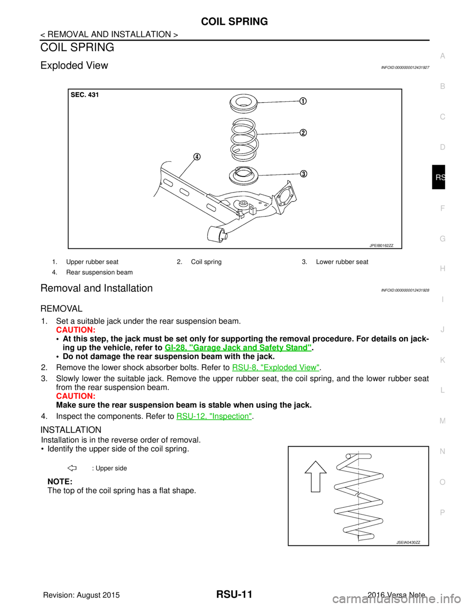
Exploded ViewINFOID:0000000012431927
Removal and InstallationINFOID:0000000012431928
REMOVAL
1. Set a suitable jack under the rear suspension beam. CAUTION:
• At this step, the jack must be set only for suppo rting the removal procedure. For details on jack-
ing up the vehicle, refer to GI-28, "
Garage Jack and Safety Stand".
• Do not damage the rear su spension beam with the jack.
2. Remove the lower shock absorber bolts. Refer to RSU-8, "
Exploded View".
3. Slowly lower the suitable jack. Remove the upper rubber seat, the coil spring, and the lower rubber seat
from the rear suspension beam.
CAUTION:
Make sure the rear susp ension beam is stable when using the jack.
4. Inspect the components. Refer to RSU-12, "
Inspection".
INSTALLATION
Installation is in the reverse order of removal.
• Identify the upper side of the coil spring.
NOTE:
The top of the coil spring has a flat shape.
1. Upper rubber seat 2. Coil spring3. Lower rubber seat
4. Rear suspension beam
JPEIB0162ZZ
: Upper side
JSEIA0430ZZ
Revision: August 2015 2016 Versa Note
cardiagn.com
Page 2740 of 3641
RSU-12
< REMOVAL AND INSTALLATION >
COIL SPRING
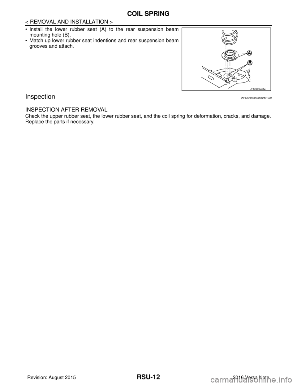
• Install the lower rubber seat (A) to the rear suspension beammounting hole (B).
• Match up lower rubber seat indentions and rear suspension beam
grooves and attach.
InspectionINFOID:0000000012431929
INSPECTION AFTER REMOVAL
Check the upper rubber seat, the lower rubber seat, and the coil spring for deformation, cracks, and damage.
Replace the parts if necessary.
JPEIB0223ZZ
Revision: August 2015 2016 Versa Note
cardiagn.com
Page 2741 of 3641
REAR SUSPENSION BEAMRSU-13
< REMOVAL AND INSTALLATION >
C
DF
G H
I
J
K L
M A
B
RSU
N
O P
REAR SUSPENSION BEAM
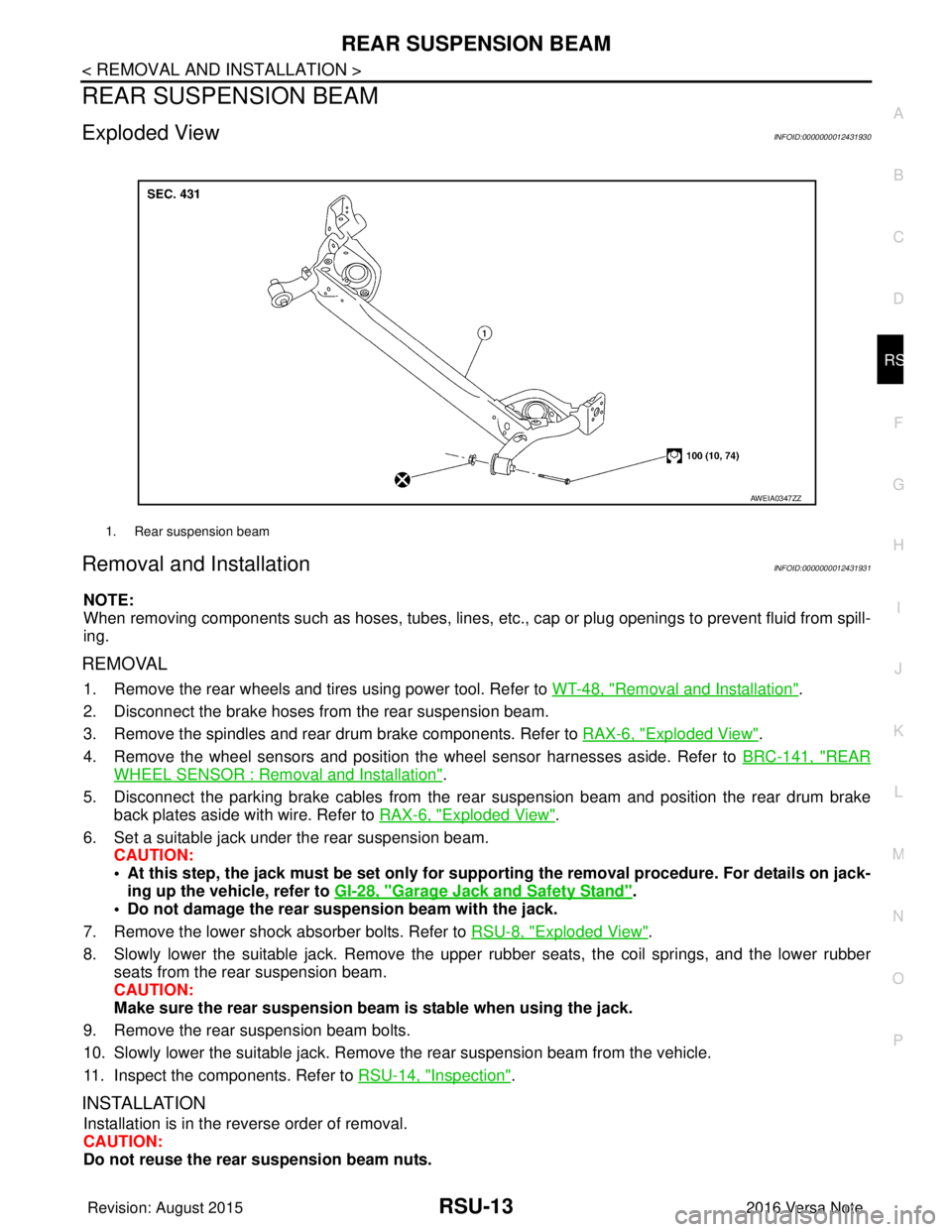
Exploded ViewINFOID:0000000012431930
Removal and InstallationINFOID:0000000012431931
NOTE:
When removing components such as hoses, tubes, lines, etc. , cap or plug openings to prevent fluid from spill-
ing.
REMOVAL
1. Remove the rear wheels and tires using power tool. Refer to WT-48, "Removal and Installation".
2. Disconnect the brake hoses from the rear suspension beam.
3. Remove the spindles and rear drum brake components. Refer to RAX-6, "
Exploded View".
4. Remove the wheel sensors and position the wheel sensor harnesses aside. Refer to BRC-141, "
REAR
WHEEL SENSOR : Removal and Installation".
5. Disconnect the parking brake cables from the rear suspension beam and position the rear drum brake
back plates aside with wire. Refer to RAX-6, "
Exploded View".
6. Set a suitable jack under the rear suspension beam. CAUTION:
• At this step, the jack must be set only for suppo rting the removal procedure. For details on jack-
ing up the vehicle, refer to GI-28, "
Garage Jack and Safety Stand".
• Do not damage the rear su spension beam with the jack.
7. Remove the lower shock absorber bolts. Refer to RSU-8, "
Exploded View".
8. Slowly lower the suitable jack. Remove the upper rubber seats, the coil springs, and the lower rubber seats from the rear suspension beam.
CAUTION:
Make sure the rear susp ension beam is stable when using the jack.
9. Remove the rear suspension beam bolts.
10. Slowly lower the suitable jack. Remove the rear suspension beam from the vehicle.
11. Inspect the components. Refer to RSU-14, "
Inspection".
INSTALLATION
Installation is in the reverse order of removal.
CAUTION:
Do not reuse the rear suspension beam nuts.
1. Rear suspension beam
AWEIA0347ZZ
Revision: August 2015 2016 Versa Note
cardiagn.com
Page 2742 of 3641
RSU-14
< REMOVAL AND INSTALLATION >
REAR SUSPENSION BEAM
• Perform the final tightening of the rear suspension beam nuts and bolts under unladen conditions with thetires on level ground.
• Adjust the parking brake. Refer to PB-4, "
Inspection and Adjustment".
• Fill the hydraulic brake system. Refer to BR-12, "
Refilling".
• Bleed the hydraulic brake system. Refer to BR-13, "
Bleeding Brake System".
• Complete the inspection. Refer to BR-12, "
Inspection".
InspectionINFOID:0000000012431932
INSPECTION AFTER REMOVAL
Check the rear suspension beam for deformation, cracks or damage. Replace the parts if necessary.
INSPECTION AFTER INSTALLATION
1. Check the wheel sensor harness to be sure the connectors are fully seated.
2. Check the neutral position of the steering angle sensor. Refer to BRC-55, "
ADJUSTMENT OF STEERING
ANGLE SENSOR NEUTRAL POSITION : Description".
3. Check the wheel alignment. Refer to RSU-6, "
Inspection".
Revision: August 2015 2016 Versa Note
cardiagn.com
Page 2744 of 3641

WT-1
SUSPENSION
C
DF
G H
I
J
K L
M
SECTION WT
A
B
WT
N
O PCONTENTS
ROAD WHEELS & TIRES
PRECAUTION ....... ........................................3
PRECAUTIONS .............................................. .....3
Precaution for Supplemental Restraint System
(SRS) "AIR BAG" and "SEAT BELT PRE-TEN-
SIONER" ............................................................. ......
3
Service Notice and Precautions for TPMS ................3
Service Notice and Precautions for Road Wheel ......3
PREPARATION ............................................5
PREPARATION .............................................. .....5
Special Service Tool ........................................... ......5
Commercial Service Tool ..........................................5
SYSTEM DESCRIPTION ..............................6
COMPONENT PARTS ................................... .....6
Component Parts Location .................................. ......6
Component Description .............................................6
BCM ..........................................................................6
Remote Keyless Entry Receiver ...............................6
Transmitter ................................................................7
Low Tire Pressure Warning Lamp .............................7
SYSTEM ......................................................... .....8
TIRE PRESSURE MONITORING SYSTEM .......... ......8
TIRE PRESSURE MONITORING SYSTEM : Sys-
tem Diagram ..............................................................
8
TIRE PRESSURE MONITORING SYSTEM : Sys-
tem Description .........................................................
8
TIRE PRESSURE MONITORING SYSTEM :
Easy Fill Tire Alert Function ......................................
8
DIAGNOSIS SYSTEM (BCM) ............................10
WITH INTELLIGENT KEY ..................................... ....10
WITH INTELLIGENT KEY : CONSULT Function
(BCM - COMMON ITEM) ........................................
10
WITH INTELLIGENT KEY : CONSULT Function
(BCM - AIR PRESSURE MONITOR) ......................
11
WITHOUT INTELLIGENT KEY .............................. ....11
WITHOUT INTELLIGENT KEY : CONSULT Func-
tion (BCM - COMMON ITEM) ..................................
11
WITHOUT INTELLIGENT KEY : CONSULT Func-
tion (BCM - AIR PRESSURE MONITOR) ...............
12
ECU DIAGNOSIS INFORMATION ..............14
BCM ...................................................................14
List of ECU Reference ......................................... ....14
WIRING DIAGRAM ......................................15
TIRE PRESSURE MONITORING SYSTEM ......15
Wiring Diagram - With Inte lligent Key ......................15
Wiring Diagram - Without Intelligent Ke y .................18
BASIC INSPECTION ....... ............................21
DIAGNOSIS AND REPAIR WORK FLOW .......21
Work Flow ............................................................ ....21
ID REGISTRATION PROCEDURE ...................22
Description ...............................................................22
Work Procedure .......................................................22
DTC/CIRCUIT DIAGNOSIS .........................25
C1704, C1705, C1706, C1707 LOW TIRE
PRESSURE .......................................................
25
DTC Logic ............................................................ ....25
Diagnosis Procedure ...............................................25
C1708, C1709, C1710, C1711 TRANSMITTER
(NO DATA) ........................................................
27
DTC Logic ............................................................ ....27
Diagnosis Procedure ...............................................27
C1716, C1717, C1718, C1719 TRANSMITTER
(PRESSURE DATA) ..........................................
30
DTC Logic ............................................................ ....30
Diagnosis Procedure ...............................................30
Revision: August 2015 2016 Versa Note
cardiagn.com
Page 2786 of 3641

NOISE, VIBRATION AND HARSHNESS (NVH) TROUBLESHOOTINGWT-43
< SYMPTOM DIAGNOSIS >
C
DF
G H
I
J
K L
M A
B
WT
N
O P
NOISE, VIBRATION AND HARSHN ESS (NVH) TROUBLESHOOTING
NVH Troubleshooting ChartINFOID:0000000012432464
Use chart below to find the cause of the symptom . If necessary, repair or replace these parts.
×: Applicable
Reference page
WT-44WT-44WT-45WT-54FSU-8—
—
WT-54FSU-5FA X - 6RAX-4RSU-4—
—
FA X - 6BR-7ST-7
Possible cause and SUSPECTED PARTS
Improper installation, looseness
Out-of-round
Imbalance
Incorrect tire pressure
Uneven tire wear
Deformation or damage
Non-uniformity
Incorrect tire size
FRONT AXLE AND FRONT SUSPENSION
REAR AXLE AND REAR SUSPENSION
TIRES
ROAD WHEELS
DRIVE SHAFT
BRAKE
STEERING
Symptom TIRENoise
××××××× × × ××××
Shake ×××××× × × × ××××
Vibration ××××××
Shimmy ×××××××× × × × ××
Shudder ×
××××× × × × × ××
Poor quality ride or
handling ×××××× × × ××
WHEEL Noise
××× × × × × ×××
Shake ××× × × × × ×××
Shimmy, Shudder ×××× ×××××
Poor quality ride or
handling ×× × ×
× × ×
Revision: August 2015 2016 Versa Note
cardiagn.com
Page 3187 of 3641
PRECAUTIONSSTC-3
< PRECAUTION >
C
DE
F
H I
J
K L
M A
B
STC
N
O P
PRECAUTION
PRECAUTIONS
Precaution for Supplemental Restraint System (SRS) "AIR BAG" and "SEAT BELT
PRE-TENSIONER"
INFOID:0000000012431939
The Supplemental Restraint System such as “AIR BAG” and “SEAT BELT PRE-TENSIONER”, used along
with a front seat belt, helps to reduce the risk or severi ty of injury to the driver and front passenger for certain
types of collision. Information necessary to service the system safely is included in the SR and SB section of
this Service Manual.
WARNING:
• To avoid rendering the SRS inoper ative, which could increase the risk of personal injury or death in
the event of a collision which would result in air bag inflation, all maintenance must be performed by
an authorized NISSAN/INFINITI dealer.
• Improper maintenance, including in correct removal and installation of the SRS, can lead to personal
injury caused by unintentional act ivation of the system. For removal of Spiral Cable and Air Bag
Module, see the SR section.
• Do not use electrical test equipm ent on any circuit related to the SRS unless instructed to in this
Service Manual. SRS wiring harnesses can be identi fied by yellow and/or orange harnesses or har-
ness connectors.
PRECAUTIONS WHEN USING POWER TOOLS (AIR OR ELECTRIC) AND HAMMERS
WARNING:
• When working near the Airbag Diagnosis Sensor Un it or other Airbag System sensors with the Igni-
tion ON or engine running, DO NOT use air or el ectric power tools or strike near the sensor(s) with a
hammer. Heavy vibration could activate the sensor( s) and deploy the air bag(s), possibly causing
serious injury.
• When using air or electric power tools or hammers, always switch the Ignition OFF, disconnect the
battery and wait at least three mi nutes before performing any service.
Service Notice and Precautions for EPS SystemINFOID:0000000012431940
• Check the following item when performing the trouble diagnosis:
- Check for possible causes of the malfunction by inte rviewing the customer as to what conditions were
present when the symptom occurred.
- Check if the steering wheel and the EPS control unit are genuine parts.
- Check if the air pressure and size of each tire is correct.
- Check if the installation of the links and suspension components are correct.
- Check if the tires are worn evenly, indicating the wheel alignment is correct.
- Check if the installation of the steering column and t he steering gear are correct. Check for loose bolts, dam-
aged links, cracked boots and leaking grease, etc.
- Check for damage or modification to suspension or body resulting in increased weight or altered ground clearance.
- Check if the battery voltage is proper.
- Check the EPS control unit harness to be sure the harness connectors are fully seated.
• Before connecting or disconnecting the EPS control uni t harness connector, turn ignition switch “OFF” and
disconnect the battery cable from the negative terminal. Battery voltage is applied to the EPS control unit
even if ignition switch is turned “OFF”.
Revision: August 2015 2016 Versa Note
cardiagn.com