Page 1860 of 3641
FRONT SUSPENSION MEMBERFSU-15
< UNIT REMOVAL AND INSTALLATION >
C
DF
G H
I
J
K L
M A
B
FSU
N
O P
• Install the member stay bolts, the upper link bolts, and the front suspension member bolts in the order of 1-6 as shown.
: Front
• After installation, perform the final tightening of each part under unladen conditions with tires on level
ground.
• Complete the inspection. FSU-15, "
Inspection"
InspectionINFOID:0000000012430313
INSPECTION AFTER REMOVAL
Check the front suspension member for cracks, wear or damage. Replace components if necessary.
INSPECTION AFTER INSTALLATION
1. Check the wheel sensor harness to be sure the connectors are fully seated.
2. Check the neutral position of the steering angle sensor. Refer to BRC-55, "
ADJUSTMENT OF STEERING
ANGLE SENSOR NEUTRAL POSITION : Description".
3. Check the wheel alignment. Refer to FSU-7, "
Inspection".
AWEIA0211ZZ
Revision: August 2015 2016 Versa Note
cardiagn.com
Page 1916 of 3641

GI-28
< PRECAUTION >
LIFTING POINT
LIFTING POINT
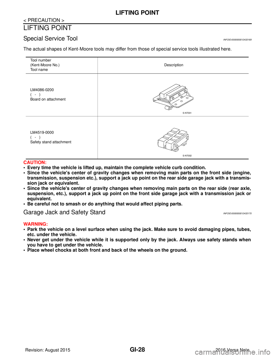
Special Service ToolINFOID:0000000012433169
The actual shapes of Kent-Moore tools may differ from those of special service tools illustrated here.
CAUTION:
• Every time the vehicle is lifted up, main tain the complete vehicle curb condition.
• Since the vehicle's center of gravity changes when removing main parts on the front side (engine, transmission, suspension etc.), supp ort a jack up point on the rear side garage jack with a transmis-
sion jack or equivalent.
• Since the vehicle's center of gravity changes when removing main parts on the rear side (rear axle,
suspension, etc.), support a jack up point on the front side garage jack with a transmission jack or
equivalent.
• Be careful not to smash or do anything that would affect piping parts.
Garage Jack and Safety StandINFOID:0000000012433170
WARNING:
• Park the vehicle on a level surface when using the jack. Make sure to avoid damaging pipes, tubes,
etc. under the vehicle.
• Never get under the vehicle while it is supported only by the jack. Always use safety stands when
you have to get under the vehicle.
• Place wheel chocks at both front an d back of the wheels on the ground.
Tool number
(Kent-Moore No.)
Tool name Description
LM4086-0200
( - )
Board on attachment
LM4519-0000
( - )
Safety stand attachment
S-NT001
S-NT002
Revision: August 2015 2016 Versa Note
cardiagn.com
Page 1917 of 3641
LIFTING POINTGI-29
< PRECAUTION >
C
DE
F
G H
I
J
K L
M B
GI
N
O P
• Lift at reinforced area of front suspension member where lower control arm attaches, staying in cen-
ter line of wheels.
2-Pole LiftINFOID:0000000012433171
WARNING:
When lifting the vehicle, open the lift arms as wide as possible and ensure that the front and rear of the
vehicle are well balanced.
Vehicle front
1. Front garage jack points 2. Safety stand points3. Rear garage jack point
ALAIA0040GB
Revision: August 2015 2016 Versa Note
cardiagn.com
Page 1919 of 3641

TOW TRUCK TOWINGGI-31
< PRECAUTION >
C
DE
F
G H
I
J
K L
M B
GI
N
O PTOW TRUCK TOWING
To w T r u c k To w i n gINFOID:0000000012433173
CAUTION:
• Never tow a CVT model with the rear wheels raised and the front wheels on the ground. This may
cause serious and expensive damage to the transaxle. If it is necessary to tow the vehicle with the
rear wheels raised, always use towin g dollies under the front wheels.
• Never tow a CVT model from the rear (that is b ackward) with four wheels on the ground. This may
cause serious and expensive damage to the transaxle.
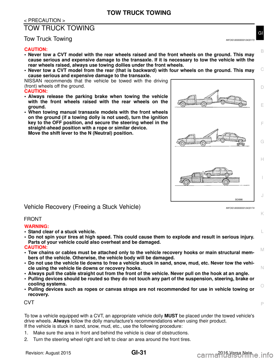
NISSAN recommends that the vehicle be towed with the driving
(front) wheels off the ground.
CAUTION:
• Always release the parking br ake when towing the vehicle
with the front wheels raised with the rear wheels on the
ground.
• When towing manual transaxle models with the front wheels on the ground (if a towing dolly is not used), turn the ignition
key to the OFF position, and secu re the steering wheel in the
straight-ahead position with a rope or similar device.
Move the shift lever to th e N (Neutral) position.
Vehicle Recovery (Freeing a Stuck Vehicle)INFOID:0000000012433174
FRONT
WARNING:
• Stand clear of a stuck vehicle.
• Do not spin your tires at high speed. This could cause them to explode and result in serious injury.
Parts of your vehicle could also overheat and be damaged.
CAUTION:
• Tow chains or cables must be attached only to the vehicle recovery hooks or main structural mem-
bers of the vehicle. Otherwise, the vehicle body will be damaged.
• Do not use the vehicle tie downs to free a vehicle stuck in sand, snow, mud, etc. Never tow the vehi-
cle using the vehicle tie downs or recovery hooks.
• Always pull the cable straight out from the front of the vehicle. Never pull on the hook at an angle.
• Pulling devices should be routed so they do not touch any part of the suspension, steering, brake or
cooling systems.
• Pulling devices such as ropes or canvas straps ar e not recommended for use in vehicle towing or
recovery.
CVT
To tow a vehicle equipped with a CVT, an appropriate vehicle dolly MUST be placed under the towed vehicle's
drive wheels. Always follow the dolly manufacture's re commendations when using their product.
If the vehicle is stuck in sand, snow , mud, etc., use the following procedure:
1. Make sure the area in front and behind the vehicle is clear of obstructions.
2. Turn the steering wheel right and left to clear an area around the front tires.
SGI986
Revision: August 2015 2016 Versa Note
cardiagn.com
Page 2317 of 3641

MA-2
BRAKE FLUID LEVEL AND LEAKS ........................34
BRAKE FLUID LEVEL AND LEAKS : Inspection ...34
BRAKE LINES AND CABLES ............................... ...34
BRAKE LINES AND CABLES : Inspection .............34
BRAKE FLUID ....................................................... ...35
BRAKE FLUID : Inspection .....................................35
BRAKE FLUID : Draining ........................................35
BRAKE FLUID : Refilling ........................................35
BRAKE FLUID : Bleeding Brake System ................36
DISC BRAKE ......................................................... ...36
DISC BRAKE : Inspection ......................................36
DISC BRAKE : Brake Burnishing ...........................37
DISC BRAKE : Inspection ......................................37
DRUM BRAKE ....................................................... ...37
DRUM BRAKE : Inspection ....................................38
DRUM BRAKE : Brake Burn ishing .........................38
DRUM BRAKE : Inspection ....................................38
STEERING GEAR AND LINKAGE ........................ ...39
STEERING GEAR AND LINKAGE : Inspection ......39
AXLE AND SUSPENSION PARTS ........................ ...39
AXLE AND SUSPENSION PARTS : Inspection .....39
DRIVE SHAFT ........................................................ ...39
DRIVE SHAFT : Inspection .....................................40
LOCKS, HINGES AND HOOD LATCH .................. ...40
LOCKS, HINGES AND HOOD LATCH : Exploded
View ..................................................................... ...
40
LOCKS, HINGES AND HOOD LATCH : Exploded
View ..................................................................... ...
41
LOCKS, HINGES AND HOOD LATCH : Exploded
View ..................................................................... ...
42
LOCKS, HINGES AND HOOD LATCH : Exploded
View ..................................................................... ...
42
SEAT BELT, BUCKLES, RETRACTORS, AN-
CHORS AND ADJUSTERS ................................... ...
43
SEAT BELT, BUCKLES, RETRACTORS, AN-
CHORS AND ADJUSTERS : Inspection .................
43
Revision: August 2015 2016 Versa Note
cardiagn.com
Page 2325 of 3641
MA-10
< PERIODIC MAINTENANCE >
PERIODIC MAINTENANCE
• Extensive idling and/or low speed driving for long distances, such as police, taxi or door-to-door delivery use.
• Driving in dusty conditions.
• Driving on rough, muddy, or salt spread roads.
• Towing a trailer, using a camper or a car-top carrier
Maintenance operation: Check = Check and correct or replace as necessary.
Maintenance itemMaintenance operation Maintenance interval Reference page
Brake fluid ReplaceEvery 10,000 miles (16,000
km) or 12 months BR-12
BR-12
Brake pads, rotors, drums &
linings
InspectEvery 5,000 miles (8,000 km)
or 6 months MA-36
MA-38
Steering gear & linkage, axle &
suspension parts
InspectEvery 5,000 miles (8,000 km)
or 6 months MA-39MA-39
MA-40
Drive shaft boots
InspectEvery 5,000 miles (8,000 km)
or 6 months MA-40
Exhaust system
InspectEvery 5,000 miles (8,000 km)
or 6 months MA-26
Revision: August 2015
2016 Versa Note
cardiagn.com
Page 2354 of 3641

CHASSIS AND BODY MAINTENANCEMA-39
< PERIODIC MAINTENANCE >
C
DE
F
G H
I
J
K L
M B
MA
N
O A
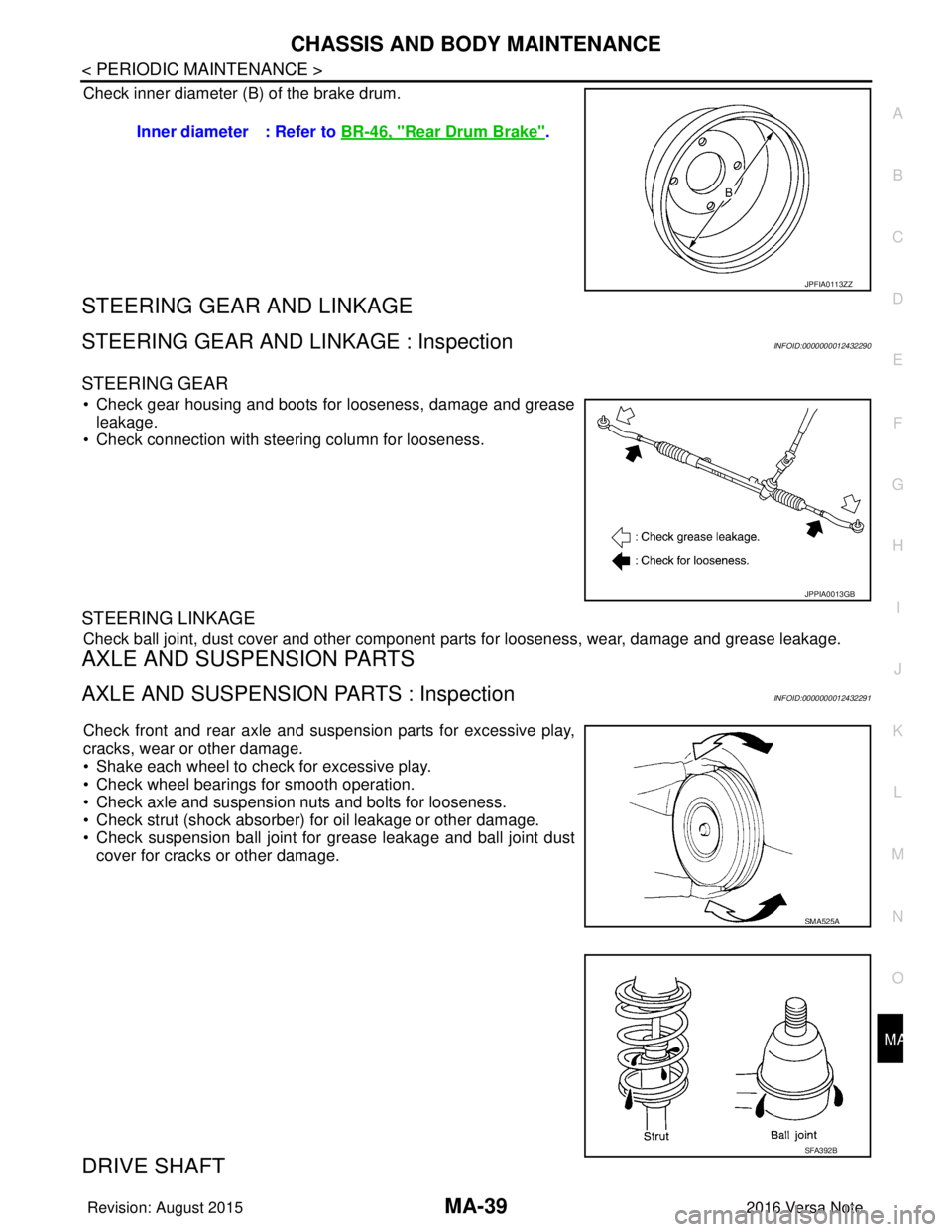
Check inner diameter (B) of the brake drum.
STEERING GEAR AND LINKAGE
STEERING GEAR AND LINKAGE : InspectionINFOID:0000000012432290
STEERING GEAR
• Check gear housing and boots for looseness, damage and grease
leakage.
• Check connection with steering column for looseness.
STEERING LINKAGE
Check ball joint, dust cover and other component parts for looseness, wear, damage and grease leakage.
AXLE AND SUSPENSION PARTS
AXLE AND SUSPENSION PARTS : InspectionINFOID:0000000012432291
Check front and rear axle and suspension parts for excessive play,
cracks, wear or other damage.
• Shake each wheel to check for excessive play.
• Check wheel bearings for smooth operation.
• Check axle and suspension nuts and bolts for looseness.
• Check strut (shock absorber) for oil leakage or other damage.
• Check suspension ball joint for grease leakage and ball joint dust
cover for cracks or other damage.
DRIVE SHAFT
Inner diameter : Refer to BR-46, "Rear Drum Brake".
JPFIA0113ZZ
JPPIA0013GB
SMA525A
SFA392B
Revision: August 2015 2016 Versa Note
cardiagn.com
Page 2722 of 3641
RAX-4
< SYMPTOM DIAGNOSIS >
NOISE, VIBRATION AND HARSHNESS (NVH) TROUBLESHOOTING
SYMPTOM DIAGNOSIS
NOISE, VIBRATION AND HARSHNESS (NVH) TROUBLESHOOTING
NVH Troubleshooting ChartINFOID:0000000012431908
Use chart below to find the cause of the symptom. If necessary, repair or replace these parts.
×: ApplicableReference page
RSU-5—
RAX-5RSU-4WT-43WT-45BR-7
Possible cause and SUSPECTED PARTS
Improper installation, looseness
Parts interference
Wheel bearing damage
REAR SUSPENSION
TIRE
ROAD WHEEL
BRAKE
Symptom Noise
×××××××
Shake ×××××××
Vibration ×××××
Shimmy ×× ××××
Shudder ×××× ×
Poor quality ride or handling ×× ×××
Revision: August 2015 2016 Versa Note
cardiagn.com