2016 NISSAN NOTE suspension
[x] Cancel search: suspensionPage 412 of 3641

BODY COMPONENT PARTSBRM-13
< PREPARATION >
C
DE
F
G H
I
J
L
M A
B
BRM
N
O P
1. Lower dash 2. Lower dash reinforcement (LH/RH) 3. Lower dash close out panel
4. Member dash cross member (LH/RH) 5. Dash side (LH/RH) 6. Front suspension bracket (LH/RH)
7. Front side member assembly (LH/
RH) 8.Lower radiator core inner side support
(LH/RH) 9. Front member extension (LH/RH)
10. Upper radiator core support (LH/RH) 11. Front side member close out plate as-
sembly (LH/RH)12.
Front side member close out plate
(LH/RH)
13. Radiator core support outer (LH/RH) 14. Strut housing assembly (LH/RH) 15. Strut housing extension (LH/RH)
16. Hood ledge (LH/RH) 17. Rear side member assembly (LH/RH) 18. Rear side member front (LH/RH)
19. Rear side member extension (LH/RH) 20. Inner sill (LH/RH) 21. Front floor side (LH/RH)
22. Front floor center 23. Rear seat back lower reinforcement 24. Rear seat back upper reinforcement
25. Rear floor rear side (LH/RH) 26. Rear floor rear 27. Rear floor cross member
28. Rear floor front 29. Rear floor front extension
A. Rear side member reinforcement (LH/
RH)
Front
Revision: August 2015
2016 Versa Note
cardiagn.com
Page 453 of 3641
![NISSAN NOTE 2016 Service Repair Manual PRECAUTIONSBRC-5
< PRECAUTION > [VDC/TCS/ABS]
C
D
E
G H
I
J
K L
M A
B
BRC
N
O P
Precaution for Brake Control SystemINFOID:0000000012430822
• Just after starting vehicle after ignition switch is ON, NISSAN NOTE 2016 Service Repair Manual PRECAUTIONSBRC-5
< PRECAUTION > [VDC/TCS/ABS]
C
D
E
G H
I
J
K L
M A
B
BRC
N
O P
Precaution for Brake Control SystemINFOID:0000000012430822
• Just after starting vehicle after ignition switch is ON,](/manual-img/5/57363/w960_57363-452.png)
PRECAUTIONSBRC-5
< PRECAUTION > [VDC/TCS/ABS]
C
D
E
G H
I
J
K L
M A
B
BRC
N
O P
Precaution for Brake Control SystemINFOID:0000000012430822
• Just after starting vehicle after ignition switch is ON, brake pedal may vibrate or motor operating noise may be heard from engine compartment. This is a normal condition.
• When an error is indicated by ABS or another warning lamp, collect all necessary information from customer
(what symptoms are present under what conditions) and check for simple causes before starting diagnostic
servicing. Besides electrical system inspection, c heck brake booster operation, brake fluid level and oil
leaks.
• If tire size and type are used in an improper combinati on or brake pads are not Genuine NISSAN parts, stop-
ping distance or steering stability may deteriorate.
• ABS might be out of order or malfunctions by putting a radio (wiring inclusive), an antenna and a lead-in wire
near the control unit.
• If aftermarket parts (car stereo, CD player, etc.) have been installed, check for incidents such as harness pinches, open circuits, and improper wiring.
• VDC system may not operate normally or a VDC OFF indi cator lamp or SLIP indicator lamp may light.
- When replacing the following parts with parts other than genuine parts or making modifications: Suspension- related parts (shock absorber, spring, bushing, etc.), tire s, wheels (other than specified sizes), brake-related
parts (pad, rotor, caliper, etc.), engine-related parts (muffler, ECM, etc.) and body reinforcement-related parts
(roll bar, tower bar, etc.).
- When driving with worn or deteriorated suspension, tires and brake-related parts.
Precaution for Harness RepairINFOID:0000000012430823
• Solder the repair part, and wrap it with tape. [Twisted wire fray
must be 110 mm (4.33 in) or less.]
• Do not bypass the repair point with wire. (If it is bypassed, the turn- out point cannot be separated and the twisted wire characteristics
are lost.)
SKIB8766E
SKIB8767E
Revision: August 2015 2016 Versa Note
cardiagn.com
Page 503 of 3641
![NISSAN NOTE 2016 Service Repair Manual INSPECTION AND ADJUSTMENTBRC-55
< BASIC INSPECTION > [VDC/TCS/ABS]
C
D
E
G H
I
J
K L
M A
B
BRC
N
O P
INSPECTION AND ADJUSTMENT
ADDITIONAL SERVICE WHEN REPLACING CONTROL UNIT
ADDITIONAL SERVICE WHEN R NISSAN NOTE 2016 Service Repair Manual INSPECTION AND ADJUSTMENTBRC-55
< BASIC INSPECTION > [VDC/TCS/ABS]
C
D
E
G H
I
J
K L
M A
B
BRC
N
O P
INSPECTION AND ADJUSTMENT
ADDITIONAL SERVICE WHEN REPLACING CONTROL UNIT
ADDITIONAL SERVICE WHEN R](/manual-img/5/57363/w960_57363-502.png)
INSPECTION AND ADJUSTMENTBRC-55
< BASIC INSPECTION > [VDC/TCS/ABS]
C
D
E
G H
I
J
K L
M A
B
BRC
N
O P
INSPECTION AND ADJUSTMENT
ADDITIONAL SERVICE WHEN REPLACING CONTROL UNIT
ADDITIONAL SERVICE WHEN REPL ACING CONTROL UNIT : Description
INFOID:0000000012545169
After replacing the ABS actuator and electric uni t (control unit), perform the following procedures:
• Neutral position adjustment for the steering angle sensor
• Calibration of the decel G sensor (if equipped)
ADDITIONAL SERVICE WHEN REPLACING CONTROL UNIT : Special Repair Re-
quirement
INFOID:0000000012545170
1.PERFORM THE NEUTRAL POSITION ADJUST MENT FOR THE STEERING ANGLE SENSOR
Perform the neutral position adjustm ent for the steering angle sensor.
>> Refer to BRC-55, "
ADJUSTMENT OF STEERING ANGLE SENSOR NEUTRAL POSITION : Spe-
cial Repair Requirement", GO TO 2
2.PERFORM CALIBRATION OF THE DECEL G SENSOR (IF EQUIPPED)
Perform calibration of the decel G sensor.
>> Refer to BRC-56, "
CALIBRATION OF DECEL G SENSOR : Special Repair Requirement".
ADJUSTMENT OF STEERING AN GLE SENSOR NEUTRAL POSITION
ADJUSTMENT OF STEERING ANGLE SEN SOR NEUTRAL POSITION : Description
INFOID:0000000012545171
Refer to the table below to determine if adjustment of steering angle sensor neutral position is required.
×: Required –: Not required
ADJUSTMENT OF STEERING ANGLE SENSOR NEUTRAL POSITION : Special Re-
pair Requirement
INFOID:0000000012545172
ADJUSTMENT OF STEERING ANGLE SENSOR NEUTRAL POSITION
CAUTION:
To adjust neutral position of steering angle sensor, make sure to use CONSULT
(Adjustment cannot be done without CONSULT)
1.ALIGN THE VEHICLE STATUS
Stop vehicle with front wheels in straight-ahead position.
Situation Adjustment of steering angle sensor neutral position
Removing/Insta lling ABS actuator and electr ic unit (control unit) —
Replacing ABS actuator and elec tric unit (control unit) ×
Removing/Installing steering angle sensor ×
Replacing steering angle sensor ×
Removing/Installing steering components ×
Replacing steering components ×
Removing/Installing suspension components ×
Replacing suspension components ×
Change tires to new ones —
Tire rotation —
Adjusting wheel alignment ×
Revision: August 20152016 Versa Note
cardiagn.com
Page 504 of 3641
![NISSAN NOTE 2016 Service Repair Manual BRC-56
< BASIC INSPECTION >[VDC/TCS/ABS]
INSPECTION AND ADJUSTMENT
>> GO TO 2
2.PERFORM THE NEUTRAL POSITION ADJUST
MENT FOR THE STEERING ANGLE SENSOR
1. On the CONSULT screen, touch “WORK SUPPORT� NISSAN NOTE 2016 Service Repair Manual BRC-56
< BASIC INSPECTION >[VDC/TCS/ABS]
INSPECTION AND ADJUSTMENT
>> GO TO 2
2.PERFORM THE NEUTRAL POSITION ADJUST
MENT FOR THE STEERING ANGLE SENSOR
1. On the CONSULT screen, touch “WORK SUPPORT�](/manual-img/5/57363/w960_57363-503.png)
BRC-56
< BASIC INSPECTION >[VDC/TCS/ABS]
INSPECTION AND ADJUSTMENT
>> GO TO 2
2.PERFORM THE NEUTRAL POSITION ADJUST
MENT FOR THE STEERING ANGLE SENSOR
1. On the CONSULT screen, touch “WORK SUPPORT” and “ST ANGLE SENSOR ADJUSTMENT” in order.
2. Touch “START”. CAUTION:
Do not touch steering wheel whil e adjusting steering angle sensor.
3. After approximately 10 seconds, touch “END”. NOTE:
After approximately 60 seconds, it ends automatically.
4. Turn ignition switch OFF, then turn it ON again. CAUTION:
Be sure to perform above operation.
>> GO TO 3
3.CHECK DATA MONITOR
1. Run vehicle with front wheels in straight-ahead position, then stop.
2. Select “DATA MONITOR”. Then make sure “STR ANGLE SIG” is within 0 ±2.5 °.
Is the steering angle within the specified range?
YES >> GO TO 4
NO >> Perform the neutral position adjustment fo r the steering angle sensor again, GO TO 1
4.ERASE THE SELF-DIAGNOSIS MEMORY
Erase the self-diagnosis memory of the ABS ac tuator and electric unit (control unit) and ECM.
• ABS actuator and electric unit (control unit): Refer to BRC-31, "
CONSULT Function (ABS)".
• ECM: Refer to EC-60, "
CONSULT Function".
Are the memories erased?
YES >> Inspection End
NO >> Check the items indicated by the self-diagnosis.
CALIBRATION OF DECEL G SENSOR
CALIBRATION OF DECEL G SENSOR : DescriptionINFOID:0000000012545173
Refer to the table below to determine if calibration of the decel G sensor is required.
×: Required –: Not required
CALIBRATION OF DECEL G SENSOR : Special Repair RequirementINFOID:0000000012545174
CALIBRATION OF DECEL G SENSOR (IF EQUIPPED)
CAUTION:
To calibrate the decel G sensor, make sure to use CONSULT
(Calibration cannot be done without CONSULT)
Situation Calibration of decel G sensor
Removing/Installing ABS actuator and electric unit (control unit) —
Replacing ABS actuator and electric unit (control unit) ×
Removing/Installing steering components —
Replacing steering components —
Removing/Installing suspension components —
Replacing suspension components —
Change tires to new ones —
Tire rotation —
Adjusting wheel alignment —
Removing/Installing yaw rate/side/decel G sensor ×
Replacing yaw rate/side/decel G sensor ×
Revision: August 20152016 Versa Note
cardiagn.com
Page 1749 of 3641

HEADLAMP AIMING ADJUSTMENTEXL-97
< PERIODIC MAINTENANCE >
C
DE
F
G H
I
J
K
M A
B
EXL
N
O P
PERIODIC MAINTENANCE
HEADLAMP AIMING ADJUSTMENT
InspectionINFOID:0000000012432828
PREPARATION BEFORE ADJUSTING
Before performing aiming adjustment, check the following:
• Ensure all tires are inflated to correct pressure.
• Place vehicle and screen on level surface.
• Ensure there is no load in vehicle other than the driver (or equivalent weight placed in driver's position).
• Coolant and engine oil filled to correct level, and fuel tank full.
• Remove cargo and/or luggage to maintain an unloaded vehicle condition.
• Confirm spare tire, jack and tools are properly stowed.
• Carefully wipe off any dirt from headlamp lens. CAUTION:
Do not use organic solvent (thinner, gasoline etc.)
• Place a driver or equivalent weight of 68.5 kg (150 lb) on the driver seat.
• By hand, bounce the front and rear of the vehicle to settle the suspension and eliminate any static load.
• Place the front tires in the straight ahead position.
• Confirm headlamp aiming switch is set to "0" (zero) position.
• Aim each headlamp individually and ensure other headlamp beam pattern is blocked from screen.
NOTE:
• For headlamp aiming details, refer to regulations in your area.
• By regulation, no means for horizontal aim adjustment is provided from the factory; only vertical aim is
adjustable.
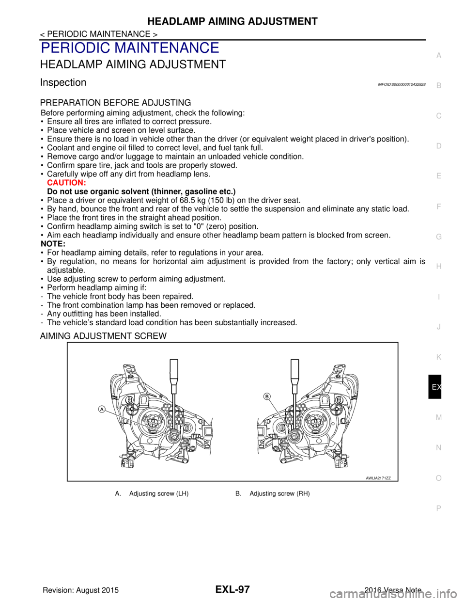
• Use adjusting screw to perform aiming adjustment.
• Perform headlamp aiming if:
- The vehicle front body has been repaired.
- The front combination lamp has been removed or replaced.
- Any outfitting has been installed.
- The vehicle’s standard load condition has been substantially increased.
AIMING ADJUSTMENT SCREW
AWLIA2171ZZ
A. Adjusting screw (LH) B. Adjusting screw (RH)
Revision: August 2015 2016 Versa Note
cardiagn.com
Page 1752 of 3641

EXL-100
< PERIODIC MAINTENANCE >
FRONT FOG LAMP AIMING ADJUSTMENT
FRONT FOG LAMP AIMING ADJUSTMENT
InspectionINFOID:0000000012432830
PREPARATION BEFORE ADJUSTING
Before performing aiming adjustment procedure, check the following:
• Ensure all tires are inflated to correct pressure.
• Place vehicle and screen on level surface.
• Ensure there is no load in vehicle other than the driver (or equivalent weight placed in driver's position).
• Coolant and engine oil filled to correct level, and fuel tank full.
• Remove cargo and/or luggage to maintain an unloaded vehicle condition.
• Confirm spare tire, jack and tools are properly stowed.
• Carefully wipe off any dirt from fog lamp lens. CAUTION:
Do not use organic solvent (thinner, gasoline etc.)
• Place a driver or equivalent weight of 68.5 kg (150 lb) on the driver seat.
• By hand, bounce the front and rear of the vehicle to settle the suspension and eliminate any static load.
• Place the front tires in the straight ahead position.
• Aim each headlamp individually and ensure other headlamp beam pattern is blocked from screen.
NOTE:
• For headlamp aiming details, refer to regulations in your area.
• By regulation, no means for horizontal aim adjustment is provided from the factory; only vertical aim is
adjustable.
• Use adjusting screw to perform aiming adjustment.
• Perform headlamp aiming if:
- The vehicle front body has been repaired.
- The front combination lamp has been removed or replaced.
- Any outfitting has been installed.
- The vehicle’s standard load condition has been substantially increased.
AIMING ADJUSTMENT SCREW
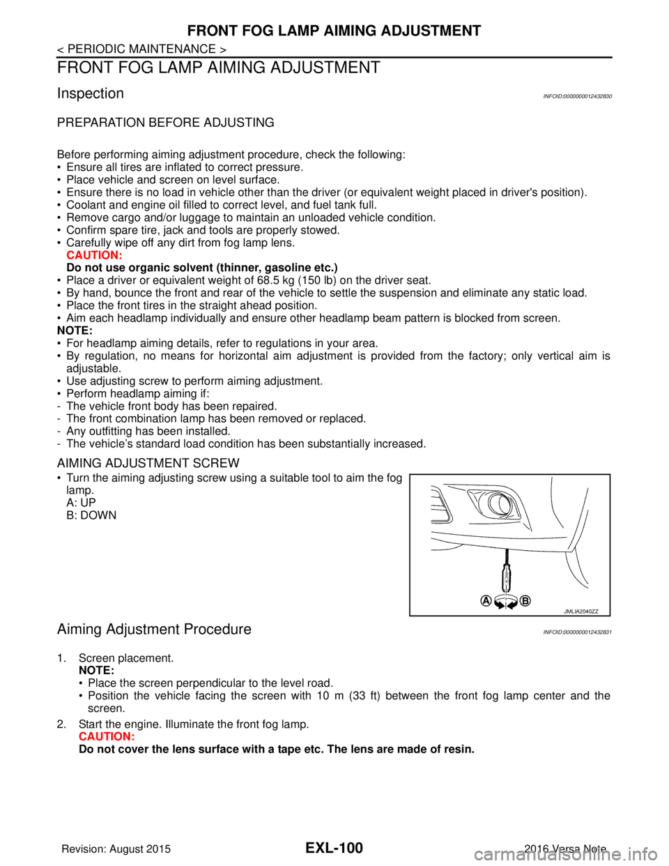
• Turn the aiming adjusting screw using a suitable tool to aim the fog
lamp.
A: UP
B: DOWN
Aiming Adjustment ProcedureINFOID:0000000012432831
1. Screen placement. NOTE:
• Place the screen perpendicular to the level road.
• Position the vehicle facing the screen with 10 m (33 ft) between the front fog lamp center and thescreen.
2. Start the engine. Illuminate the front fog lamp. CAUTION:
Do not cover the lens surface with a tape etc. The lens are made of resin.
JMLIA2040ZZ
Revision: August 2015 2016 Versa Note
cardiagn.com
Page 1823 of 3641

FAX-6
< SYMPTOM DIAGNOSIS >
NOISE, VIBRATION AND HARSHNESS (NVH) TROUBLESHOOTING
SYMPTOM DIAGNOSIS
NOISE, VIBRATION AND HARSHNESS (NVH) TROUBLESHOOTING
NVH Troubleshooting ChartINFOID:0000000012431887
Use chart below to find the cause of the symptom. If necessary, repair or replace these parts.
×: ApplicableReference
—
FAX-8—
FAX-8—
FSU-5FSU-5—
WT-45WT-44—
BR-7ST-7
Possible cause and SUSPECTED PARTS
Excessive joint angle
Joint sliding resistance
Imbalance
Improper installation, looseness
Parts interference
Wheel bearing damage
FRONT SUSPENSION
FRONT AXLE
TIRE
ROAD WHEEL
DRIVE SHAFT
BRAKE
STEERING
Symptom DRIVE
SHAFT
Noise
××××××× ××
Shake × × ××××× ××
FRONT
AXLE Noise
×××× ×××××
Shake ×××× ×××××
Vibration ×××××××
Shimmy ×××××××
Shudder × × ×× ××
Poor quality ride or handling ×××××
Revision: August 2015 2016 Versa Note
cardiagn.com
Page 1824 of 3641

FRONT WHEEL HUB AND KNUCKLEFAX-7
< PERIODIC MAINTENANCE >
CEF
G H
I
J
K L
M A
B
FA X
N
O P
PERIODIC MAINTENANCE
FRONT WHEEL HUB AND KNUCKLE
InspectionINFOID:0000000012431888
COMPONENT PART
• Check that the mounting conditions (looseness, ba cklash) of each component and component conditions
(wear, damage) are normal.
• Check the axle and suspension parts for excessive play, weary or damage.
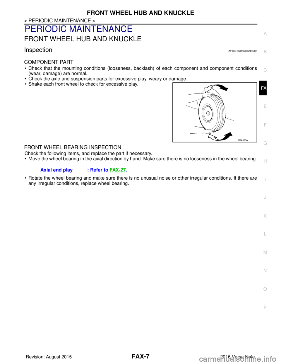
• Shake each front wheel to check for excessive play.
FRONT WHEEL BEARING INSPECTION
Check the following items, and replace the part if necessary.
• Move the wheel bearing in the axial direction by hand. Make sure there is no looseness in the wheel bearing.
• Rotate the wheel bearing and make sure there is no unusual noise or other irregular conditions. If there are any irregular conditions, replace wheel bearing.
SMA525A
Axial end play : Refer to FA X - 2 7.
Revision: August 2015 2016 Versa Note
cardiagn.com