2016 NISSAN NOTE trans
[x] Cancel search: transPage 2672 of 3641

DIAGNOSIS SYSTEM (BCM) (WITHOUT INTELLIGENT KEY SYSTEM)PWC-11
< SYSTEM DESCRIPTION >
C
DE
F
G H
I
J
L
M A
B
PWC
N
O P
DIAGNOSIS SYSTEM (BCM) (WITHO UT INTELLIGENT KEY SYSTEM)
COMMON ITEM
COMMON ITEM : CONSULT Function (BCM - COMMON ITEM)INFOID:0000000012542486
APPLICATION ITEM
CONSULT performs the following functions via CAN communication with BCM.
SYSTEM APPLICATION
BCM can perform the following functions.
Direct Diagnostic Mode Description
ECU Identification The BCM part number is displayed.
Self Diagnostic Result The BCM self diagnostic results are displayed.
Data Monitor The BCM input/output data is displayed in real time.
Active Test The BCM activates outputs to test components.
Work support The settings for BCM functions can be changed.
Configuration • The vehicle specification can be read and saved.
• The vehicle specification can be written when replacing BCM.
CAN DIAG SUPPORT MNTR The result of transmit/receive diagnosis of CAN communication is displayed.
System Sub System Direct Diagnostic Mode
ECU Identification
Self Diagnostic Result
Data Monitor
Active Test
Work support
Configuration
CAN DIAG SUPPORT MNTR
Door lock
DOOR LOCK ×××
Rear window defogger REAR DEFOGGER ××
Warning chime BUZZER ××
Interior room lamp timer INT LAMP ×××
Remote keyless entry system MULTI REMOTE ENT ×××
Exterior lamp HEAD LAMP ×××
Wiper and washer WIPER ×××
Turn signal and hazard warning lamps FLASHER ××
Air conditioner AIR CONDITIONER ×
Combination switch COMB SW ×
BCM BCM× × ×××
Immobilizer IMMU ×××
Interior room lamp battery saver BATTERY SAVER ×××
Vehicle security system THEFT ALM ××
RAP system RETAINED PWR ××
Signal buffer system SIGNAL BUFFER ×
TPMS AIR PRESSURE MONITOR ××××
Panic alarm system PANIC ALARM ×
Revision: August 2015 2016 Versa Note
cardiagn.com
Page 2719 of 3641

RAX-1
TRANSMISSION & DRIVELINE
CEF
G H
I
J
K L
M
SECTION RAX
A
B
RAX
N
O P
CONTENTS
REAR AXLE
PRECAUTION ....... ........................................2
PRECAUTIONS .............................................. .....2
Precaution for Supplemental Restraint System
(SRS) "AIR BAG" and "SEAT BELT PRE-TEN-
SIONER" ............................................................. ......
2
Precautions for Wheel Hub .......................................2
PREPARATION ............................................3
PREPARATION .............................................. .....3
Special Service Tools .......................................... ......3
Commercial Service Tool ..........................................3
SYMPTOM DIAGNOSIS ...............................4
NOISE, VIBRATION AND HARSHNESS
(NVH) TROUBLESHOOTING ........................ .....
4
NVH Troubleshooting Chart ................................ ......4
PERIODIC MAINTENANCE .........................5
REAR WHEEL HUB ...........................................5
Inspection ............................................................ .....5
REMOVAL AND INSTALLATION ................6
REAR WHEEL HUB ...........................................6
Exploded View ..................................................... .....6
Removal and Installation ..........................................6
Disassembly and Assembly ......................................7
Inspection .................................................................9
SERVICE DATA AND SPECIFICATIONS
(SDS) ............... .......................................... ...
10
SERVICE DATA AND SPECIFICATIONS
(SDS) .................................................................
10
Wheel Bearing ..................................................... ....10
Wheel Hub ...............................................................10
Revision: August 2015 2016 Versa Note
cardiagn.com
Page 2744 of 3641

WT-1
SUSPENSION
C
DF
G H
I
J
K L
M
SECTION WT
A
B
WT
N
O PCONTENTS
ROAD WHEELS & TIRES
PRECAUTION ....... ........................................3
PRECAUTIONS .............................................. .....3
Precaution for Supplemental Restraint System
(SRS) "AIR BAG" and "SEAT BELT PRE-TEN-
SIONER" ............................................................. ......
3
Service Notice and Precautions for TPMS ................3
Service Notice and Precautions for Road Wheel ......3
PREPARATION ............................................5
PREPARATION .............................................. .....5
Special Service Tool ........................................... ......5
Commercial Service Tool ..........................................5
SYSTEM DESCRIPTION ..............................6
COMPONENT PARTS ................................... .....6
Component Parts Location .................................. ......6
Component Description .............................................6
BCM ..........................................................................6
Remote Keyless Entry Receiver ...............................6
Transmitter ................................................................7
Low Tire Pressure Warning Lamp .............................7
SYSTEM ......................................................... .....8
TIRE PRESSURE MONITORING SYSTEM .......... ......8
TIRE PRESSURE MONITORING SYSTEM : Sys-
tem Diagram ..............................................................
8
TIRE PRESSURE MONITORING SYSTEM : Sys-
tem Description .........................................................
8
TIRE PRESSURE MONITORING SYSTEM :
Easy Fill Tire Alert Function ......................................
8
DIAGNOSIS SYSTEM (BCM) ............................10
WITH INTELLIGENT KEY ..................................... ....10
WITH INTELLIGENT KEY : CONSULT Function
(BCM - COMMON ITEM) ........................................
10
WITH INTELLIGENT KEY : CONSULT Function
(BCM - AIR PRESSURE MONITOR) ......................
11
WITHOUT INTELLIGENT KEY .............................. ....11
WITHOUT INTELLIGENT KEY : CONSULT Func-
tion (BCM - COMMON ITEM) ..................................
11
WITHOUT INTELLIGENT KEY : CONSULT Func-
tion (BCM - AIR PRESSURE MONITOR) ...............
12
ECU DIAGNOSIS INFORMATION ..............14
BCM ...................................................................14
List of ECU Reference ......................................... ....14
WIRING DIAGRAM ......................................15
TIRE PRESSURE MONITORING SYSTEM ......15
Wiring Diagram - With Inte lligent Key ......................15
Wiring Diagram - Without Intelligent Ke y .................18
BASIC INSPECTION ....... ............................21
DIAGNOSIS AND REPAIR WORK FLOW .......21
Work Flow ............................................................ ....21
ID REGISTRATION PROCEDURE ...................22
Description ...............................................................22
Work Procedure .......................................................22
DTC/CIRCUIT DIAGNOSIS .........................25
C1704, C1705, C1706, C1707 LOW TIRE
PRESSURE .......................................................
25
DTC Logic ............................................................ ....25
Diagnosis Procedure ...............................................25
C1708, C1709, C1710, C1711 TRANSMITTER
(NO DATA) ........................................................
27
DTC Logic ............................................................ ....27
Diagnosis Procedure ...............................................27
C1716, C1717, C1718, C1719 TRANSMITTER
(PRESSURE DATA) ..........................................
30
DTC Logic ............................................................ ....30
Diagnosis Procedure ...............................................30
Revision: August 2015 2016 Versa Note
cardiagn.com
Page 2745 of 3641

WT-2
C1729 VEHICLE SPEED SIGNAL ....................32
DTC Logic ............................................................ ...32
Diagnosis Procedure ..............................................32
LOW TIRE PRESSURE WARNING LAMP .......33
Component Function Check ................................ ...33
Diagnosis Procedure ..............................................33
POWER SUPPLY AND GROUND CIRCUIT .....34
WITH INTELLIGENT KEY ...................................... ...34
WITH INTELLIGENT KEY : Diagnosis Procedure ...34
WITHOUT INTELLIGENT KEY .............................. ...34
WITHOUT INTELLIGENT KEY : Diagnosis Proce-
dure ........................................................................
34
SYMPTOM DIAGNOSIS .............................36
TPMS SYMPTOMS ......................................... ...36
Symptom Table ................................................... ...36
LOW TIRE PRESSURE WARNING LAMP
DOES NOT TURN ON .......................................
37
Diagnosis Procedure ..............................................37
LOW TIRE PRESSURE WARNING LAMP
DOES NOT TURN OFF .....................................
38
Diagnosis Procedure ........................................... ...38
LOW TIRE PRESSURE WARNING LAMP
BLINKS ..............................................................
39
Diagnosis Procedure ........................................... ...39
EASY FILL TIRE ALERT DOES NOT ACTI-
VATE ..................................................................
40
Description ........................................................... ...40
Diagnosis Procedure ..............................................40
ID REGISTRATION CANNOT BE COMPLET-
ED ......................................................................
42
Diagnosis Procedure ............................................ ...42
NOISE, VIBRATION AND HARSHNESS
(NVH) TROUBLESHOOTING ............................
43
NVH Troubleshooting Chart ....................................43
PERIODIC MAINTENANCE .......................44
WHEEL ........................................................... ...44
Inspection ............................................................. ...44
WHEEL AND TIRE ............................................45
Adjustment ........................................................... ...45
REMOVAL AND INSTALLATION ..............48
WHEEL AND TIRE ......................................... ...48
Exploded View ..................................................... ...48
Removal and Installation .........................................48
TRANSMITTER .............................................. ...49
Exploded View ..................................................... ...49
Removal and Installation .........................................49
Disposal ............................................................... ...52
TIRE PRESSURE RECEIVER ...........................53
Removal and Installation .........................................53
SERVICE DATA AND SPECIFICATIONS
(SDS) .......... ................................. ...............
54
SERVICE DATA AND SPECIFICATIONS
(SDS) .............................................................. ...
54
Wheel ................................................................... ...54
Tire Air Pressure .....................................................54
Revision: August 2015 2016 Versa Note
cardiagn.com
Page 2748 of 3641

PREPARATIONWT-5
< PREPARATION >
C
DF
G H
I
J
K L
M A
B
WT
N
O P
PREPARATION
PREPARATION
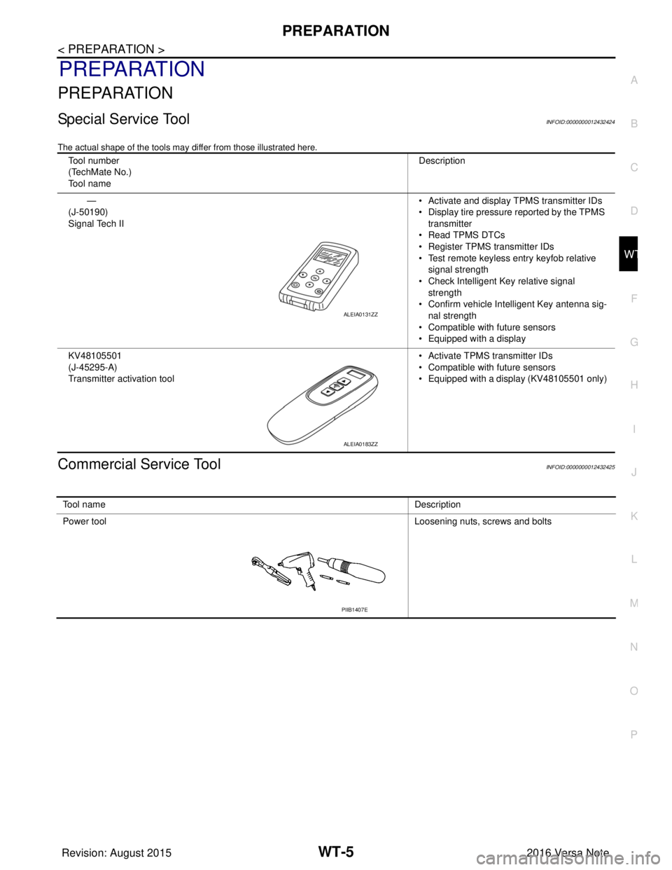
Special Service ToolINFOID:0000000012432424
The actual shape of the tools may di ffer from those illustrated here.
Commercial Service ToolINFOID:0000000012432425
Tool number
(TechMate No.)
Tool name Description
—
(J-50190)
Signal Tech II • Activate and display TPMS transmitter IDs
• Display tire pressure reported by the TPMS
transmitter
• Read TPMS DTCs
• Register TPMS transmitter IDs
• Test remote keyless entry keyfob relative signal strength
• Check Intelligent Key relative signal strength
• Confirm vehicle Intelligent Key antenna sig-
nal strength
• Compatible with future sensors
• Equipped with a display
KV48105501
(J-45295-A)
Transmitter activation tool • Activate TPMS transmitter IDs
• Compatible with future sensors
• Equipped with a display (KV48105501 only)
ALEIA0131ZZ
ALEIA0183ZZ
To o l n a m e
Description
Power tool Loosening nuts, screws and bolts
PIIB1407E
Revision: August 2015 2016 Versa Note
cardiagn.com
Page 2749 of 3641

WT-6
< SYSTEM DESCRIPTION >
COMPONENT PARTS
SYSTEM DESCRIPTION
COMPONENT PARTS
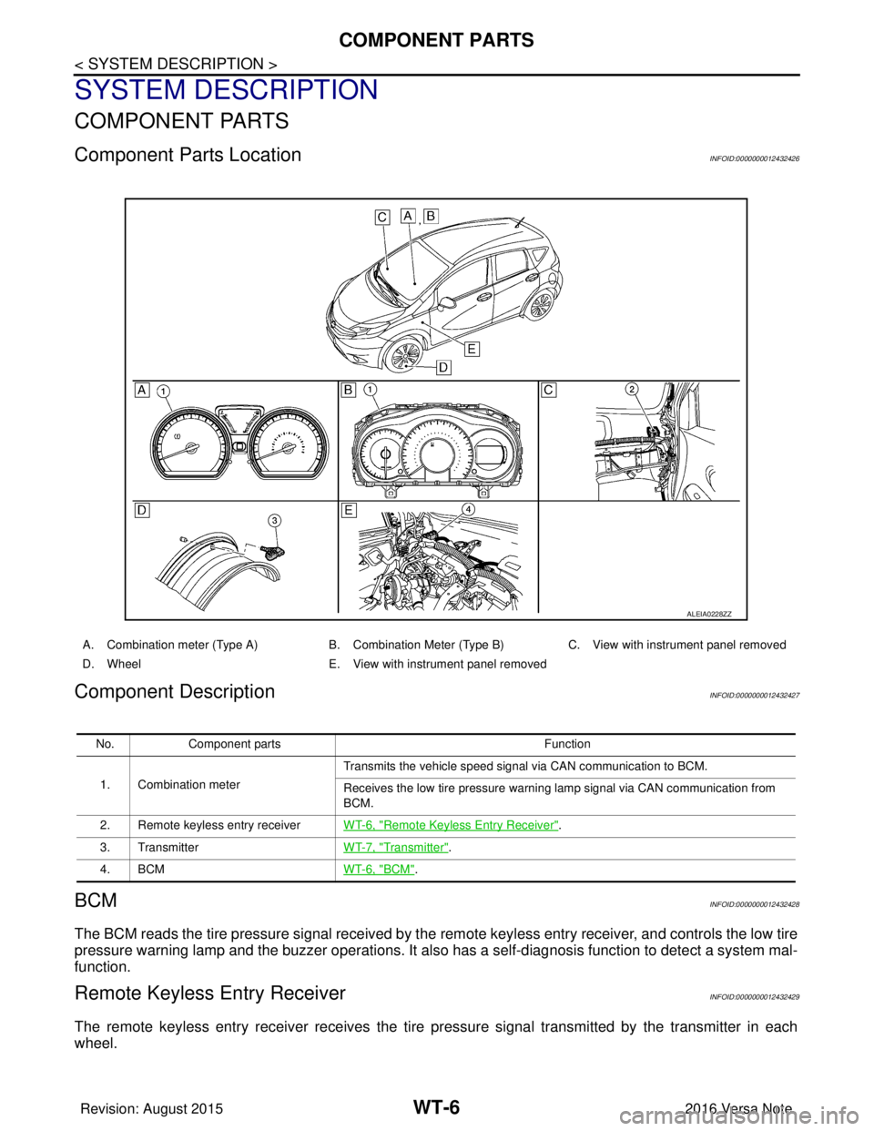
Component Parts LocationINFOID:0000000012432426
Component DescriptionINFOID:0000000012432427
BCMINFOID:0000000012432428
The BCM reads the tire pressure signal received by the remote keyless entry receiver, and controls the low tire
pressure warning lamp and the buzzer operations. It also has a self-diagnosis function to detect a system mal-
function.
Remote Keyless Entry ReceiverINFOID:0000000012432429
The remote keyless entry receiver receives the tire pressure signal transmitted by the transmitter in each
wheel.
ALEIA0228ZZ
A. Combination meter (Type A) B. Combination Meter (Type B)C. View with instrument panel removed
D. Wheel E. View with instrument panel removed
No. Component parts Function
1. Combination meter Transmits the vehicle speed signal via CAN communication to BCM.
Receives the low tire pressure warning lamp signal via CAN communication from
BCM.
2. Remote keyless entry receiver WT-6, "
Remote Keyless Entry Receiver".
3. Transmitter WT-7, "
Transmitter".
4. BCM WT-6, "
BCM".
Revision: August 2015 2016 Versa Note
cardiagn.com
Page 2750 of 3641

COMPONENT PARTSWT-7
< SYSTEM DESCRIPTION >
C
DF
G H
I
J
K L
M A
B
WT
N
O P
TransmitterINFOID:0000000012432430
A sensor-transmitter integrated with a valve is installed in each wheel, and transmits a detected tire pressure
signal in the form of a radio wave. The radio signal is received by the remote keyless entry receiver.
Low Tire Pressure Warning LampINFOID:0000000012432431
The combination meter receives tire pressure status from the BCM using CAN communication. When a low
tire pressure condition is sensed by the BCM, the combi nation meter low tire pressure warning lamp is acti-
vated.
Revision: August 2015 2016 Versa Note
cardiagn.com
Page 2751 of 3641

WT-8
< SYSTEM DESCRIPTION >
SYSTEM
SYSTEM
TIRE PRESSURE MONITORING SYSTEM
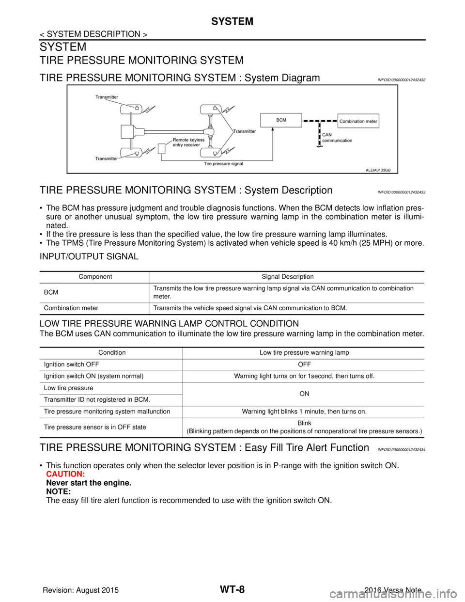
TIRE PRESSURE MONITORING SYSTEM : System DiagramINFOID:0000000012432432
TIRE PRESSURE MONITORING SY STEM : System DescriptionINFOID:0000000012432433
• The BCM has pressure judgment and trouble diagnosis functions. When the BCM detects low inflation pres-
sure or another unusual symptom, the low tire pressure warning lamp in the combination meter is illumi-
nated.
• If the tire pressure is less than the specified value, the low tire pressure warning lamp illuminates.
• The TPMS (Tire Pressure Monitoring System) is activated when vehicle s peed is 40 km/h (25 MPH) or more.
INPUT/OUTPUT SIGNAL
LOW TIRE PRESSURE WARNING LAMP CONTROL CONDITION
The BCM uses CAN communication to illuminate the low tire pressure warning lamp in the combination meter.
TIRE PRESSURE MONITORING SYSTEM : Easy Fill Tire Alert FunctionINFOID:0000000012432434
• This function operates only when the selector lever position is in P-range with the ignition switch ON.
CAUTION:
Never start the engine.
NOTE:
The easy fill tire alert function is reco mmended to use with the ignition switch ON.
ALEIA0133GB
Component Signal Description
BCM Transmits the low tire pressure warning lamp signal via CAN communication to combination
meter.
Combination meter Transmits the vehicle speed signal via CAN communication to BCM.
Condition Low tire pressure warning lamp
Ignition switch OFF OFF
Ignition switch ON (system normal) Warning light turns on for 1second, then turns off.
Low tire pressure ON
Transmitter ID not registered in BCM.
Tire pressure monitoring system malfunction Warning light blinks 1 minute, then turns on.
Tire pressure sensor is in OFF state Blink
(Blinking pattern depends on the positions of nonoperational tire pressure sensors.)
Revision: August 2015 2016 Versa Note
cardiagn.com