2016 NISSAN NOTE trans
[x] Cancel search: transPage 2771 of 3641

WT-28
< DTC/CIRCUIT DIAGNOSIS >
C1708, C1709, C1710, C1711 TRANSMITTER (NO DATA)
2.CHECK REMOTE KEYLESS ENTRY RECEIVER POWER CIRCUIT
Check voltage between remote keyless entry receiver connector and ground.
Is the inspection result normal?
YES >> GO TO 3.
NO >> Repair or replace harness or connectors.
3.CHECK REMOTE KEYL ESS ENTRY RECEIVER SIGNAL CIRCUIT
1. Turn the ignition switch OFF.
2. Disconnect BCM and remote keyless entry receiver connectors.
3. Check continuity between BCM and remote keyless entry receiver connectors.
4. Check continuity between BCM connector and ground.
Is the inspection result normal?
YES >> GO TO 4.
NO >> Repair or replace the ma lfunctioning harness or connector.
4.CHECK REMOTE KEYLESS ENTRY RECEIVER GROUND CIRCUIT
Check continuity between BCM and remote keyless entry receiver connectors.
Is the inspection result normal?
YES >> GO TO 5.
NO >> Repair or replace the ma lfunctioning harness or connector.
5.TRANSMITTER ID REGISTRATION
Perform transmitter ID registration. Refer to WT-22, "
Work Procedure".
Is transmitter ID registration completed?
YES >> GO TO 6.
NO >> Replace applicable transmitter. Refer to WT-49, "
Removal and Installation".
6.CHECK TIRE PRESSURE SIGNAL
With CONSULT
1. Drive for 3 minutes at a speed of 40 km/h (25 MPH) or more, then drive normally for 10 minutes.
2. Stop the vehicle.
3. On “DATA MONITOR” select “AIR PRESS FL”, “A IR PRESS FR”, “AIR PRESS RR” and “AIR PRESS RL”.
Remote keyless entry receiver
GroundVo l ta g e
(Approx.)
Connector Terminal
M94 (with Intelligent Key system) 1
—Battery voltage
M23 (without Intelligent Key system) 4 5V
BCMRemote keyless entry receiver
Continuity
Connector TerminalConnector Terminal
M97 (with Intelligent Key system) 38 M94 (with Intelligent Key system)
2Yes
M18 (without Intelligent Key system) 20 M23 (without Intelligent Key system)
BCM —Continuity
Connector Terminal
M97 (with Intelligent Key system) 38 GroundNo
M18 (without Intelligent Key system) 20
BCMRemote keyless entry receiver
Continuity
Connector TerminalConnector Terminal
M97 (with Intelligent Key system) 18M94 (with Intelligent Key system)
4
Ye s
M18 (without Intelligent Key system) M23 (without Intelligent Key system) 1
Revision: August 2015 2016 Versa Note
cardiagn.com
Page 2772 of 3641

C1708, C1709, C1710, C1711 TRANSMITTER (NO DATA)
WT-29
< DTC/CIRCUIT DIAGNOSIS >
C
DF
G H
I
J
K L
M A
B
WT
N
O P
4. Within 5 minutes after vehicle stopped, check that t he tire pressures are within specification. Refer to WT-
54, "Tire Air Pressure".
Is the inspection result normal?
YES >> Inspection End.
NO >> Replace the BCM. Refer to BCS-74, "
Removal and Installation" (with Intelligent Key system) or
BCS-137, "
Removal and Installation" (without Intelligent Key system).
Monitor item Displayed value
AIR PRESS FL Approximately equal to the indication on tire gauge value for front LH tire
AIR PRESS FR Approximately equal to the indication on tire gauge value for front RH tire
AIR PRESS RR Approximately equal to the indication on tire gauge value for rear RH tire
AIR PRESS RL Approximately equal to the indication on tire gauge value for rear LH tire
Revision: August 2015 2016 Versa Note
cardiagn.com
Page 2773 of 3641

WT-30
< DTC/CIRCUIT DIAGNOSIS >
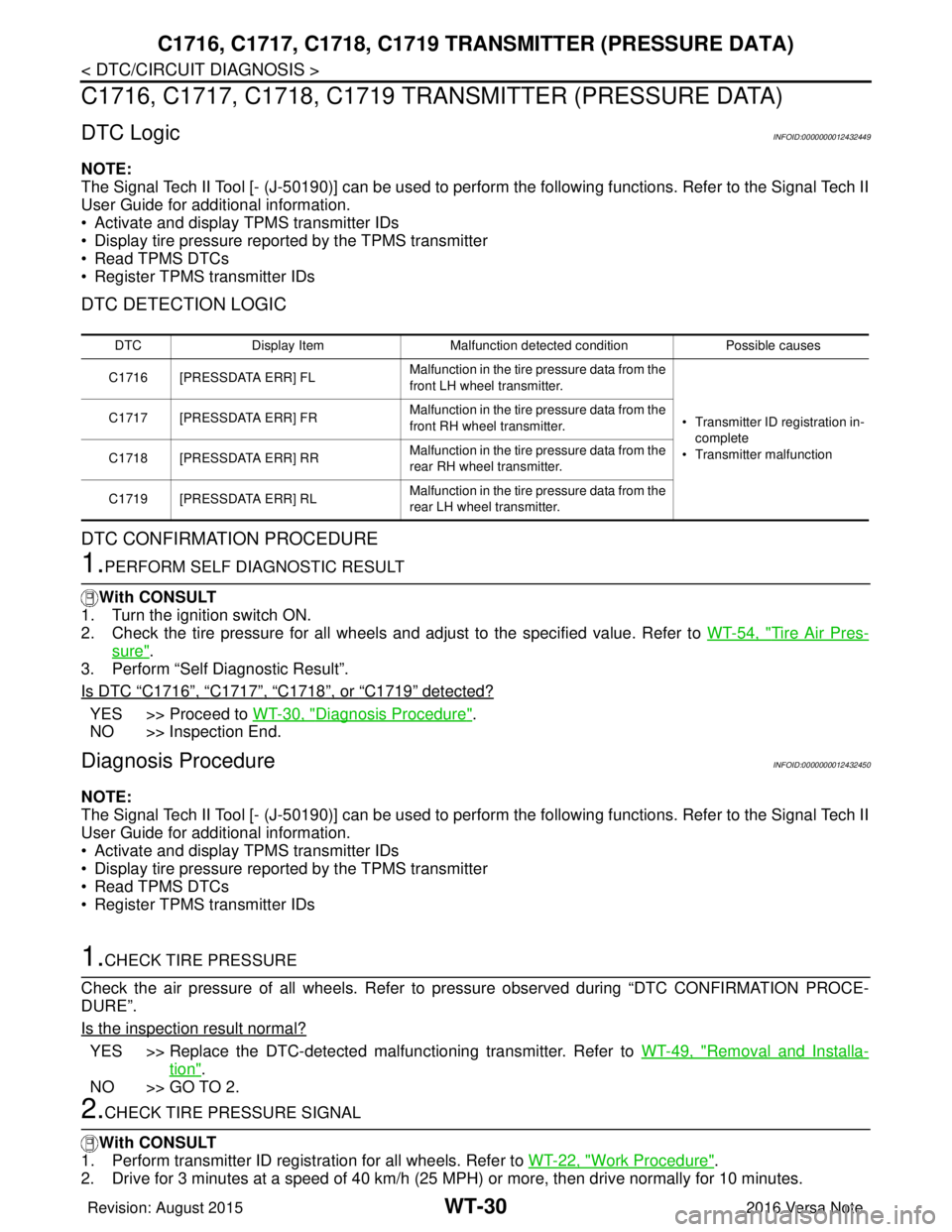
C1716, C1717, C1718, C1719 TRANSMITTER (PRESSURE DATA)
C1716, C1717, C1718, C1719 TRAN SMITTER (PRESSURE DATA)
DTC LogicINFOID:0000000012432449
NOTE:
The Signal Tech II Tool [- (J-50190)] can be used to perform the following functions. Refer to the Signal Tech II
User Guide for additional information.
• Activate and display TPMS transmitter IDs
• Display tire pressure reported by the TPMS transmitter
• Read TPMS DTCs
• Register TPMS transmitter IDs
DTC DETECTION LOGIC
DTC CONFIRMATION PROCEDURE
1.PERFORM SELF DIAGNOSTIC RESULT
With CONSULT
1. Turn the ignition switch ON.
2. Check the tire pressure for all wheels and adjust to the specified value. Refer to WT-54, "
Tire Air Pres-
sure".
3. Perform “Self Diagnostic Result”.
Is DTC
“C1716”, “C1717”, “C1718”, or “C1719” detected?
YES >> Proceed to WT-30, "Diagnosis Procedure".
NO >> Inspection End.
Diagnosis ProcedureINFOID:0000000012432450
NOTE:
The Signal Tech II Tool [- (J-50190)] can be used to perform the following functions. Refer to the Signal Tech II
User Guide for additional information.
• Activate and display TPMS transmitter IDs
• Display tire pressure reported by the TPMS transmitter
• Read TPMS DTCs
• Register TPMS transmitter IDs
1.CHECK TIRE PRESSURE
Check the air pressure of all wheels. Refer to pressure observed during “DTC CONFIRMATION PROCE-
DURE”.
Is the inspection result normal?
YES >> Replace the DTC-detected malfunctioning transmitter. Refer to WT-49, "Removal and Installa-
tion".
NO >> GO TO 2.
2.CHECK TIRE PRESSURE SIGNAL
With CONSULT
1. Perform transmitter ID regist ration for all wheels. Refer to WT-22, "
Work Procedure".
2. Drive for 3 minutes at a speed of 40 km/h (25 MPH) or more, then drive normally for 10 minutes.
DTC Display Item Malfunction detected condition Possible causes
C1716 [PRESSDATA ERR] FL Malfunction in the tire pressure data from the
front LH wheel transmitter.
• Transmitter ID registration in-
complete
• Transmitter malfunction
C1717 [PRESSDATA ERR] FR
Malfunction in the tire pressure data from the
front RH wheel transmitter.
C1718 [PRESSDATA ERR] RR Malfunction in the tire pressure data from the
rear RH wheel transmitter.
C1719 [PRESSDATA ERR] RL Malfunction in the tire pressure data from the
rear LH wheel transmitter.
Revision: August 2015
2016 Versa Note
cardiagn.com
Page 2774 of 3641

C1716, C1717, C1718, C1719 TRANSMITTER (PRESSURE DATA)
WT-31
< DTC/CIRCUIT DIAGNOSIS >
C
DF
G H
I
J
K L
M A
B
WT
N
O P
3. Stop the vehicle.
4. On “DATA MONITOR” select “AIR PRESS FL”, “AIR PRESS FR”, “AIR PRESS RR” and “AIR PRESS RL”.
5. Within 5 minutes after vehicle is stopped, read the values displayed on CONSULT.
Are tire pressures displayed as 438.6 kPa (4.47 kg/cm
2, 63.6 psi)?
YES >> Replace transmitter for the tire that displayed pressure as 438.6 kPa (4.47 kg/cm2, 63.6 psi).
Refer to WT-49, "
Removal and Installation".
NO >> Perform “DTC CONFIRMATION PROCEDURE” again. Refer to WT-30, "
DTC Logic".
Revision: August 2015 2016 Versa Note
cardiagn.com
Page 2775 of 3641
![NISSAN NOTE 2016 Service Repair Manual WT-32
< DTC/CIRCUIT DIAGNOSIS >
C1729 VEHICLE SPEED SIGNAL
C1729 VEHICLE SPEED SIGNAL
DTC LogicINFOID:0000000012432451
NOTE:
The Signal Tech II Tool [- (J-50190)] can be used to perform the following NISSAN NOTE 2016 Service Repair Manual WT-32
< DTC/CIRCUIT DIAGNOSIS >
C1729 VEHICLE SPEED SIGNAL
C1729 VEHICLE SPEED SIGNAL
DTC LogicINFOID:0000000012432451
NOTE:
The Signal Tech II Tool [- (J-50190)] can be used to perform the following](/manual-img/5/57363/w960_57363-2774.png)
WT-32
< DTC/CIRCUIT DIAGNOSIS >
C1729 VEHICLE SPEED SIGNAL
C1729 VEHICLE SPEED SIGNAL
DTC LogicINFOID:0000000012432451
NOTE:
The Signal Tech II Tool [- (J-50190)] can be used to perform the following functions. Refer to the Signal Tech II
User Guide for additional information.
• Activate and display TPMS transmitter IDs
• Display tire pressure reported by the TPMS transmitter
• Read TPMS DTCs
• Register TPMS transmitter IDs
DTC DETECTION LOGIC
DTC CONFIRMATION PROCEDURE
1.PERFORM SELF DIAGNOSTIC RESULT
With CONSULT
1. Drive for 3 minutes at a speed of 40 km/h (25 MPH) or more without stopping.
2. Stop the vehicle.
3. Perform “Self Diagnostic Result”.
Is DTC
“C1729” detected?
YES >> Proceed to WT-32, "Diagnosis Procedure".
NO >> Inspection End.
Diagnosis ProcedureINFOID:0000000012432452
NOTE:
The Signal Tech II Tool [- (J-50190)] can be used to perform the following functions. Refer to the Signal Tech II
User Guide for additional information.
• Activate and display TPMS transmitter IDs
• Display tire pressure reported by the TPMS transmitter
• Read TPMS DTCs
• Register TPMS transmitter IDs
1.PERFORM COMBINATION METER SELF DIAGNOSTIC RESULT
With CONSULT
Perform “Self Diagnostic Result” for “METER/M&A”. Refer to MWI-18, "
CONSULT Function (METER/M&A)"
(type A) or MWI-71, "CONSULT Function (METER/M&A)" (type B).
Are any DTCs detected?
YES >> Refer to MWI-24, "DTC Index" (type A) or MWI-77, "DTC Index" (type B).
NO >> GO TO 2.
2.CHECK BCM INPUT/OUTPUT SIGNAL
Check the BCM input/output signal values. Refer to BCS-30, "
Reference Value" (with Intelligent Key system)
or BCS-101, "
Reference Value" (without Intelligent Key system).
Is the inspection result normal?
YES >> Check pin terminal and connection of each harness connector for malfunctioning conditions.
NO >> Replace the BCM. Refer to BCS-74, "
Removal and Installation" (with Intelligent Key system) or
BCS-137, "
Removal and Installation" (without Intelligent Key system).
DTC Display Item Malfunction detected condition Possible causes
C1729 VHCL SPEED SIG ERR Vehicle speed signal not detected. • CAN communication malfunction
• Combination meter malfunction
Revision: August 2015
2016 Versa Note
cardiagn.com
Page 2780 of 3641

LOW TIRE PRESSURE WARNING LAMP DOES NOT TURN ON
WT-37
< SYMPTOM DIAGNOSIS >
C
D F
G H
I
J
K L
M A
B
WT
N
O P
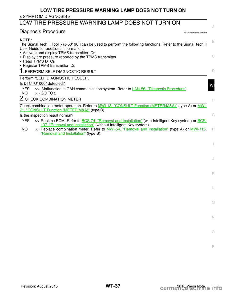
LOW TIRE PRESSURE WARNIN G LAMP DOES NOT TURN ON
Diagnosis ProcedureINFOID:0000000012432458
NOTE:
The Signal Tech II Tool [- (J-50190)] can be used to perform the following functions. Refer to the Signal Tech II
User Guide for additional information.
• Activate and display TPMS transmitter IDs
• Display tire pressure reported by the TPMS transmitter
• Read TPMS DTCs
• Register TPMS transmitter IDs
1.PERFORM SELF DIAGNOSTIC RESULT
Perform “SELF DIAGNOSTIC RESULT”.
Is DTC
“U1000” detected?
YES >> Malfunction in CAN communication system. Refer to LAN-56, "Diagnosis Procedure".
NO >> GO TO 2
2.CHECK COMBINATION METER
Check combination meter operation. Refer to MWI-18, "
CONSULT Function (METER/M&A)" (type A) or MWI-
71, "CONSULT Function (METER/M&A)" (type B).
Is the inspection result normal?
YES >> Replace BCM. Refer to BCS-74, "Removal and Installation" (with Intelligent Key system) or BCS-
137, "Removal and Installation" (without Intelligent Key system).
NO >> Replace combination meter. Refer to MWI-54, "
Removal and Installation" (type A) or MWI-115,
"Removal and Installation" (type B).
Revision: August 2015 2016 Versa Note
cardiagn.com
Page 2782 of 3641

LOW TIRE PRESSURE WARNING LAMP BLINKSWT-39
< SYMPTOM DIAGNOSIS >
C
DF
G H
I
J
K L
M A
B
WT
N
O P
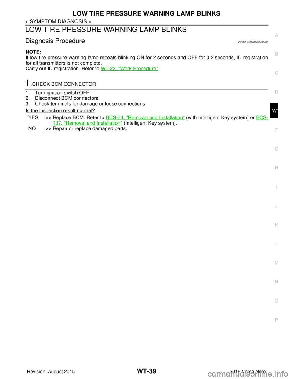
LOW TIRE PRESSURE WA RNING LAMP BLINKS
Diagnosis ProcedureINFOID:0000000012432460
NOTE:
If low tire pressure warning lamp repeats blinking ON for 2 seconds and OFF for 0.2 seconds, ID registration
for all transmitters is not complete.
Carry out ID registration. Refer to WT-22, "
Work Procedure".
1.CHECK BCM CONNECTOR
1. Turn ignition switch OFF.
2. Disconnect BCM connectors.
3. Check terminals for damage or loose connections.
Is the inspection result normal?
YES >> Replace BCM. Refer to BCS-74, "Removal and Installation" (with Intelligent Key system) or BCS-
137, "Removal and Installation" (Intelligent Key system).
NO >> Repair or replace damaged parts.
Revision: August 2015 2016 Versa Note
cardiagn.com
Page 2783 of 3641

WT-40
< SYMPTOM DIAGNOSIS >
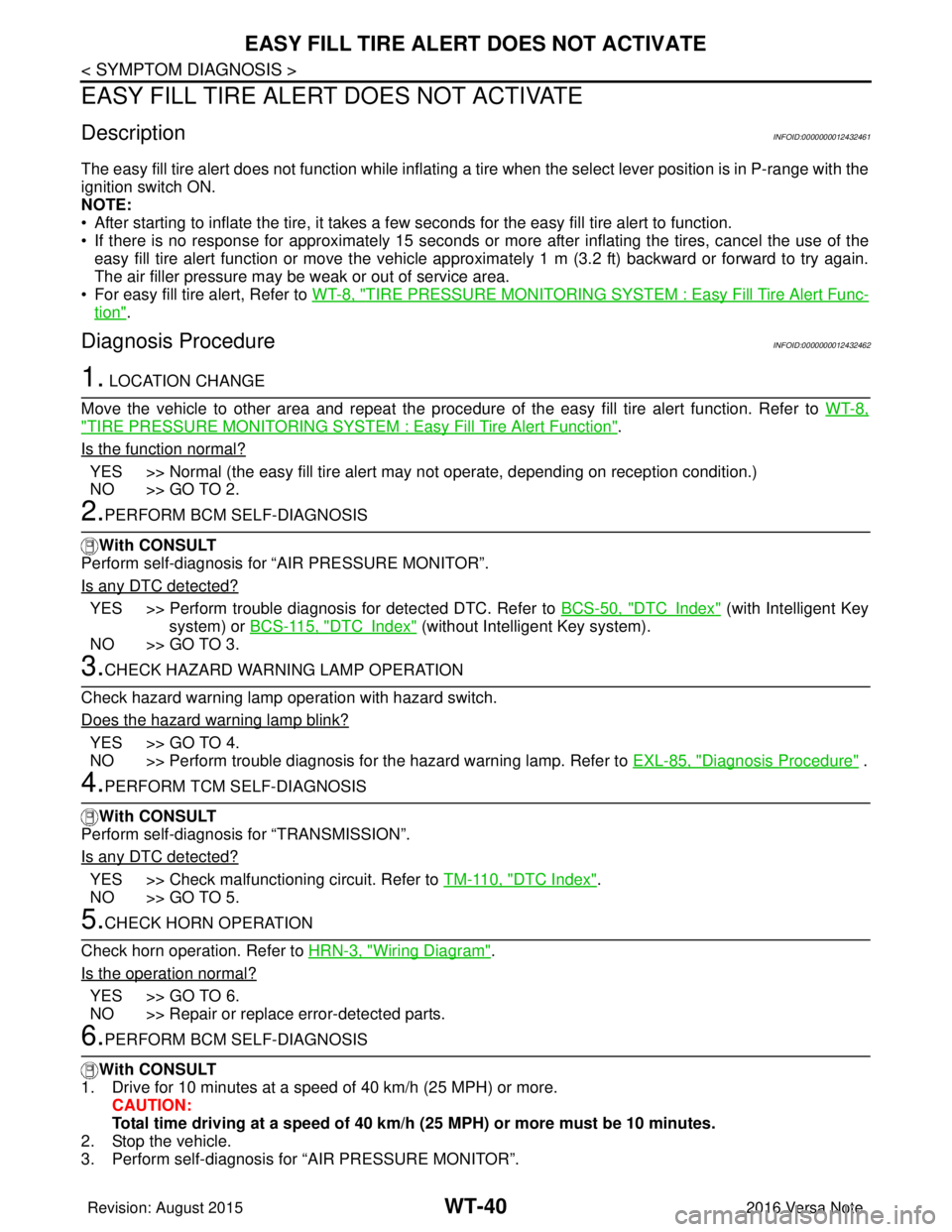
EASY FILL TIRE ALERT DOES NOT ACTIVATE
EASY FILL TIRE ALERT DOES NOT ACTIVATE
DescriptionINFOID:0000000012432461
The easy fill tire alert does not function while inflating a tire when the select lever position is in P-range with the
ignition switch ON.
NOTE:
• After starting to inflate the tire, it takes a few seconds for the easy fill tire alert to function.
• If there is no response for approximately 15 seconds or mo re after inflating the tires, cancel the use of the
easy fill tire alert function or move the vehicle approximately 1 m (3.2 ft) backward or forward to try again.
The air filler pressure may be weak or out of service area.
• For easy fill tire alert, Refer to WT-8, "
TIRE PRESSURE MONITORING SYST EM : Easy Fill Tire Alert Func-
tion".
Diagnosis ProcedureINFOID:0000000012432462
1. LOCATION CHANGE
Move the vehicle to other area and repeat the procedure of the easy fill tire alert function. Refer to WT-8,
"TIRE PRESSURE MONITORING SYSTEM : Easy Fill Tire Alert Function".
Is the function normal?
YES >> Normal (the easy fill tire alert may not operate, depending on reception condition.)
NO >> GO TO 2.
2.PERFORM BCM SELF-DIAGNOSIS
With CONSULT
Perform self-diagnosis for “AIR PRESSURE MONITOR”.
Is any DTC detected?
YES >> Perform trouble diagnosis for detected DTC. Refer to BCS-50, "DTCIndex" (with Intelligent Key
system) or BCS-115, "
DTCIndex" (without Intelligent Key system).
NO >> GO TO 3.
3.CHECK HAZARD WARNING LAMP OPERATION
Check hazard warning lamp operation with hazard switch.
Does the hazard warning lamp blink?
YES >> GO TO 4.
NO >> Perform trouble diagnosis for the hazard warning lamp. Refer to EXL-85, "
Diagnosis Procedure" .
4.PERFORM TCM SELF-DIAGNOSIS
With CONSULT
Perform self-diagnosis for “TRANSMISSION”.
Is any DTC detected?
YES >> Check malfunctioning circuit. Refer to TM-110, "DTC Index".
NO >> GO TO 5.
5.CHECK HORN OPERATION
Check horn operation. Refer to HRN-3, "
Wiring Diagram".
Is the operation normal?
YES >> GO TO 6.
NO >> Repair or replace error-detected parts.
6.PERFORM BCM SELF-DIAGNOSIS
With CONSULT
1. Drive for 10 minutes at a speed of 40 km/h (25 MPH) or more.
CAUTION:
Total time driving at a speed of 40 km/h (25 MPH) or more must be 10 minutes.
2. Stop the vehicle.
3. Perform self-diagnosis for “AIR PRESSURE MONITOR”.
Revision: August 2015 2016 Versa Note
cardiagn.com