2016 NISSAN NOTE trans
[x] Cancel search: transPage 2785 of 3641
![NISSAN NOTE 2016 Service Repair Manual WT-42
< SYMPTOM DIAGNOSIS >
ID REGISTRATION CANNOT BE COMPLETED
ID REGISTRATION CANNOT BE COMPLETED
Diagnosis ProcedureINFOID:0000000012432463
NOTE:
The Signal Tech II Tool [- (J-50190)] can be used t NISSAN NOTE 2016 Service Repair Manual WT-42
< SYMPTOM DIAGNOSIS >
ID REGISTRATION CANNOT BE COMPLETED
ID REGISTRATION CANNOT BE COMPLETED
Diagnosis ProcedureINFOID:0000000012432463
NOTE:
The Signal Tech II Tool [- (J-50190)] can be used t](/manual-img/5/57363/w960_57363-2784.png)
WT-42
< SYMPTOM DIAGNOSIS >
ID REGISTRATION CANNOT BE COMPLETED
ID REGISTRATION CANNOT BE COMPLETED
Diagnosis ProcedureINFOID:0000000012432463
NOTE:
The Signal Tech II Tool [- (J-50190)] can be used to perform the following functions. Refer to the Signal Tech II
User Guide for additional information.
• Activate and display TPMS transmitter IDs
• Display tire pressure reported by the TPMS transmitter
• Read TPMS DTCs
• Register TPMS transmitter IDs
1.PERFORM ID REGISTRATION OF ALL TRANSMITTERS
Carry out ID registration of all transmitters. Refer to WT-22, "
Work Procedure".
Can ID registration of all transmitters be completed?
YES >> Inspection End.
NO >> Refer to WT-11, "
WITH INTELLIGENT KEY : CONSULT F unction (BCM - AIR PRESSURE MON-
ITOR)" (with Intelligent Key system) or WT-12, "WITHOUT INTELLIGENT KEY : CONSULT Func-
tion (BCM - AIR PRESSURE MONITOR)" (without Intelligent Key system).
Revision: August 2015 2016 Versa Note
cardiagn.com
Page 2792 of 3641

TRANSMITTERWT-49
< REMOVAL AND INSTALLATION >
C
DF
G H
I
J
K L
M A
B
WT
N
O P
TRANSMITTER
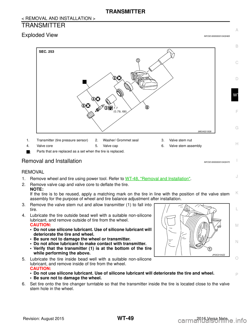
Exploded ViewINFOID:0000000012432469
Removal and InstallationINFOID:0000000012432470
REMOVAL
1. Remove wheel and tire using power tool. Refer to WT-48, "Removal and Installation".
2. Remove valve cap and valve core to deflate the tire. NOTE:
If the tire is to be reused, apply a matching mark on the tire in line with the position of the valve stem
assembly for the purpose of wheel and tire balance adjustment after installation.
3. Remove the valve stem nut and allow transmitter (1) to fall into tire.
4. Lubricate the tire outside bead well with a suitable non-silicone lubricant, and remove outside of tire from the wheel.
CAUTION:
• Do not use silicone lubricant. Use of silicone lubricant will
deteriorate the tire and wheel.
• Be sure not to damage the wheel or transmitter.
• Do not allow lubricant to make contact with transmitter.
• Verify that the transmitter (1) is at the bottom of the tire while performing the above.
5. Lubricate the tire inside bead well with a suitable non-silicone lubricant, and remove inside of tire from the wheel.
CAUTION:
• Do not use silicone lubricant. Use of silicone lubricant will deteriorate the tire and wheel.
• Be sure not to damage the wheel.
6. Set tire onto the tire changer turntable so that the transmitter inside the tire is located close to the valve stem hole in the wheel.
1. Transmitter (tire pressure sensor) 2. Washer/ Grommet seal 3. Valve stem nut
4. Valve core 5. Valve cap6. Valve stem assembly
: Parts that are replaced as a set when the tire is replaced.
JMEIA0210GB
JPEIC0104ZZ
Revision: August 2015
2016 Versa Note
cardiagn.com
Page 2793 of 3641

WT-50
< REMOVAL AND INSTALLATION >
TRANSMITTER
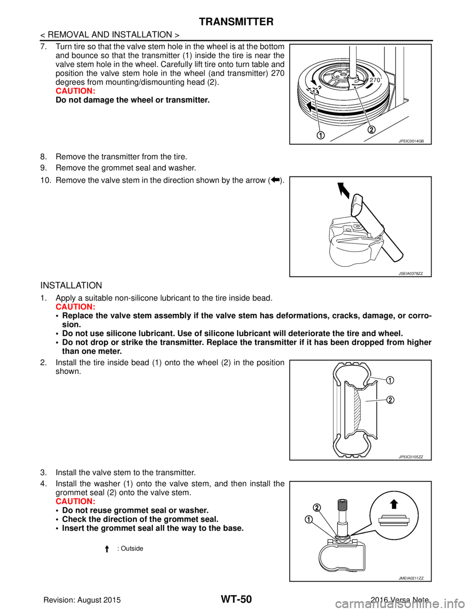
7. Turn tire so that the valve stem hole in the wheel is at the bottom
and bounce so that the transmitter (1) inside the tire is near the
valve stem hole in the wheel. Carefully lift tire onto turn table and
position the valve stem hole in the wheel (and transmitter) 270
degrees from mounting/dismounting head (2).
CAUTION:
Do not damage the wheel or transmitter.
8. Remove the transmitter from the tire.
9. Remove the grommet seal and washer.
10. Remove the valve stem in the direction shown by the arrow ( ).
INSTALLATION
1. Apply a suitable non-silicone lubricant to the tire inside bead. CAUTION:
• Replace the valve stem assembly if the valve stem has deformations, cracks, damage, or corro-
sion.
• Do not use silicone lubricant. Use of silicone lubricant will deteriorate the tire and wheel.
• Do not drop or strike the transmitter. Replace the transmitter if it has been dropped from higher
than one meter.
2. Install the tire inside bead (1) onto the wheel (2) in the position shown.
3. Install the valve stem to the transmitter.
4. Install the washer (1) onto the valve stem, and then install the grommet seal (2) onto the valve stem.
CAUTION:
• Do not reuse grommet seal or washer.
• Check the direction of the grommet seal.
• Insert the grommet seal all the way to the base.
JPEIC0014GB
JSEIA0378ZZ
JPEIC0105ZZ
: Outside
JMEIA0211ZZ
Revision: August 2015 2016 Versa Note
cardiagn.com
Page 2794 of 3641

TRANSMITTERWT-51
< REMOVAL AND INSTALLATION >
C
DF
G H
I
J
K L
M A
B
WT
N
O P
CAUTION:
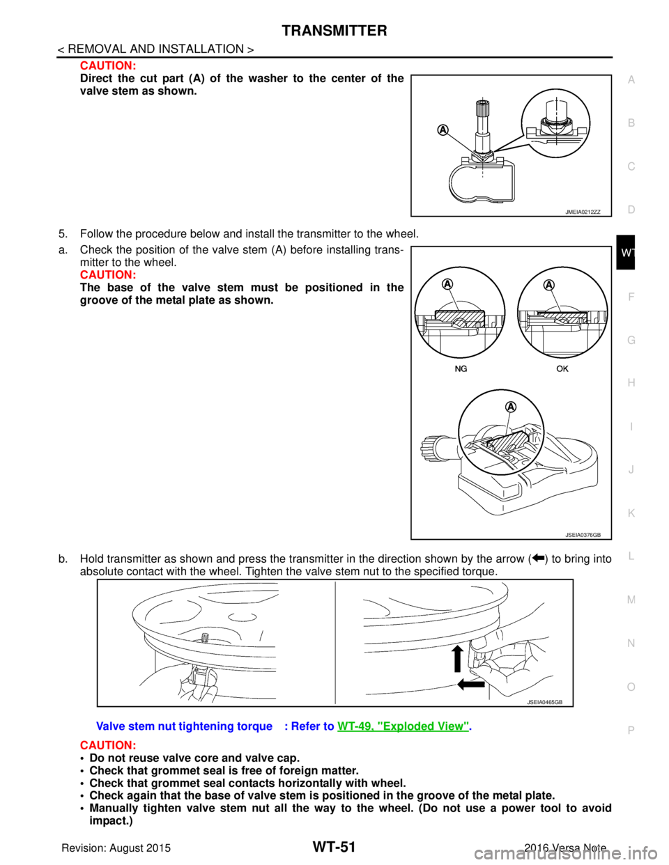
Direct the cut part (A) of the washer to the center of the
valve stem as shown.
5. Follow the procedure below and install the transmitter to the wheel.
a. Check the position of the valve stem (A) before installing trans-
mitter to the wheel.
CAUTION:
The base of the valve stem mu st be positioned in the
groove of the metal plate as shown.
b. Hold transmitter as shown and press the transmitter in the direction shown by the arrow ( ) to bring into absolute contact with the wheel. Tighten the valve stem nut to the specified torque.
CAUTION:
• Do not reuse valve core and valve cap.
• Check that grommet seal is free of foreign matter.
• Check that grommet seal contacts horizontally with wheel.
• Check again that the base of valve stem is po sitioned in the groove of the metal plate.
• Manually tighten valve stem nut all the way to the wheel. (Do not use a power tool to avoid
impact.)
JMEIA0212ZZ
JSEIA0376GB
Valve stem nut tightening torque : Refer to WT-49, "Exploded View".
JSEIA0465GB
Revision: August 2015 2016 Versa Note
cardiagn.com
Page 2795 of 3641

WT-52
< REMOVAL AND INSTALLATION >
TRANSMITTER
• Do not tighten valve stem nut to more than the specified torque. It may cause grommet seal dam-age.
• Do not tighten valve stem nut to less than th e specified torque. It may cause an air leak.
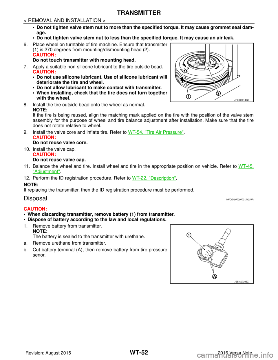
6. Place wheel on turntable of tire machine. Ensure that transmitter (1) is 270 degrees from mounting/dismounting head (2).
CAUTION:
Do not touch transmitter with mounting head.
7. Apply a suitable non-silicone lubricant to the tire outside bead. CAUTION:
• Do not use silicone lubricant. Use of silicone lubricant will
deteriorate the tire and wheel.
• Do not allow lubricant to make contact with transmitter.
• When installing, check that the tire does not turn together with the wheel.
8. Install the tire outside bead onto the wheel as normal. NOTE:
If the tire is being reused, align the matching mark applied on the tire with the position of the valve stem
assembly for the purpose of wheel and tire balance adjus tment after installation. Make sure that the tire
does not rotate relative to wheel.
9. Install the valve core and inflate tire. Refer to WT-54, "
Tire Air Pressure".
CAUTION:
Do not reuse valve core.
10. Install the valve cap. CAUTION:
Do not reuse valve cap.
11. Balance the wheel and tire. Install wheel and tire in the appropriate position on vehicle. Refer to WT-45,
"Adjustment".
12. Perform the ID registration procedure. Refer to WT-22, "
Description".
NOTE:
If replacing the transmitter, then the ID registration procedure must be performed.
DisposalINFOID:0000000012432471
CAUTION:
• When discarding transmitter, remove battery (1) from transmitter.
• Dispose of battery according to the law and local regulations.
1. Remove battery from transmitter. NOTE:
The battery is sealed to the transmitter with urethane.
a. Remove urethane from transmitter.
b. Cut battery terminal (A), then remove battery from tire pressure senor.
JPEIC0014GB
JSEIA0729ZZ
Revision: August 2015 2016 Versa Note
cardiagn.com
Page 2824 of 3641

SQUEAK AND RATTLE TROUBLE DIAGNOSESSE-11
< SYMPTOM DIAGNOSIS >
C
DE
F
G H
I
K L
M A
B
SE
N
O P
1. Loose harness or harness connectors.
2. Front console map/reading lamp lens loose.
3. Loose screws at console attachment points.
SEATS
When isolating seat noise it's important to note the position the seat is in and the load placed on the seat when
the noise is present. These conditions should be duplicated when verifying and isolating the cause of the
noise.
Cause of seat noise include:
1. Headrest rods and holder
2. A squeak between the seat pad cushion and frame
3. The rear seatback lock and bracket
These noises can be isolated by moving or pressing on the suspected components while duplicating the con-
ditions under which the noise occurs. Most of thes e incidents can be repaired by repositioning the component
or applying urethane tape to the contact area.
UNDERHOOD
Some interior noise may be caused by components under the hood or on the engine wall. The noise is then
transmitted into the passenger compartment.
Causes of transmitted underhood noise include:
1. Any component installed to the engine wall
2. Components that pass through the engine wall
3. Engine wall mounts and connectors
4. Loose radiator installation pins
5. Hood bumpers out of adjustment
6. Hood striker out of adjustment
These noises can be difficult to isolate since they cannot be reached from the interior of the vehicle. The best
method is to secure, move or insulate one component at a time and test drive the vehicle. Also, engine rpm or
load can be changed to isolate the noise. Repairs can usually be made by moving, adjusting, securing, or
insulating the component causing the noise.
Revision: August 2015 2016 Versa Note
cardiagn.com
Page 2858 of 3641

SEC-1
BODY EXTERIOR, DOORS, ROOF & VEHICLE SECURITY
C
DE
F
G H
I
J
L
M
SECTION SEC
A
B
SEC
N
O P
CONTENTS
SECURITY CONTROL SYSTEM
WITH INTELLIGENT KEY SYSTEM
PRECAUTION ....... ........................................
5
PRECAUTIONS .............................................. .....5
Precaution for Supplemental Restraint System
(SRS) "AIR BAG" and "SEAT BELT PRE-TEN-
SIONER" ............................................................. ......
5
Precaution for Work ..................................................5
PREPARATION ............................................6
PREPARATION .............................................. .....6
Special Service Tool ........................................... ......6
SYSTEM DESCRIPTION ..............................7
COMPONENT PARTS ................................... .....7
Component Parts Location .................................. ......7
CVT Shift Selector (Park Position Switch) ................9
BCM ..........................................................................9
ECM ..........................................................................9
IPDM E/R ................................................................10
NATS Antenna Amp. ...............................................10
Combination Meter ..................................................10
Door Switch .............................................................10
Outside Key Antenna ..............................................10
Inside Key Antenna .................................................10
Remote Keyless Entry Receiver .............................10
Intelligent Key ..........................................................10
Push-button Ignition Switch .....................................10
Security Indicator Lamp ...................................... ....10
Starter Relay ...........................................................10
Stop Lamp Switch ...................................................11
Transmission Range Switch ....................................11
SYSTEM .............................................................12
INTELLIGENT KEY SYSTEM/ENGINE START
FUNCTION ............................................................. ....
12
INTELLIGENT KEY SYSTEM/ENGINE START
FUNCTION : System Description ............................
12
NISSAN ANTI-THEFT SYSTEM ................................14
NISSAN ANTI-THEFT SYST EM : System De-
scription ............................................................... ....
15
DIAGNOSIS SYSTEM (BCM) ...........................18
COMMON ITEM ..................................................... ....18
COMMON ITEM : CONSULT Function (BCM -
COMMON ITEM) .....................................................
18
INTELLIGENT KEY ................................................ ....19
INTELLIGENT KEY : CONSULT Function (BCM -
INTELLIGENT KEY) ................................................
19
THEFT ALM ........................................................... ....21
THEFT ALM : CONSULT Function (BCM -
THEFT) ....................................................................
21
IMMU ...................................................................... ....21
IMMU : CONSULT Function (BCM - IMMU) ............21
ECU DIAGNOSIS INFORMATION ..............23
ECM, IPDM E/R, BCM .......................................23
List of ECU Reference ......................................... ....23
WIRING DIAGRAM ......................................24
INTELLIGENT KEY SYSTEM/ENGINE
START FUNCTION ...........................................
24
Wiring Diagram .................................................... ....24
NVIS - WITH INTELLIGENT KEY SYSTEM .....37
Wiring Diagram ........................................................37
BASIC INSPECTION ...................................46
DIAGNOSIS AND REPAIR WORK FLOW .......46
Work Flow ............................................................ ....46
ADDITIONAL SERVICE WHEN REPLACING
CONTROL UNIT ................................................
49
ECM ........................................................................ ....49
Revision: August 2015 2016 Versa Note
cardiagn.com
Page 2859 of 3641

SEC-2
ECM : Description ...................................................49
ECM : Work Procedure ...........................................49
BCM ........................................................................ ...49
BCM : Description ...................................................49
BCM : Work Procedure ...........................................49
DTC/CIRCUIT DIAGNOSIS ...................... ...51
P1610 LOCK MODE ....................................... ...51
Description ........................................................... ...51
DTC Logic ...............................................................51
Diagnosis Procedure ..............................................51
P1611 ID DISCORD, IMMU-ECM ......................52
DTC Logic ............................................................ ...52
Diagnosis Procedure ..............................................52
P1612 CHAIN OF ECM-IMMU ...........................53
DTC Logic ............................................................ ...53
Diagnosis Procedure ..............................................53
B2192 ID DISCORD, IMMU-ECM ......................54
DTC Logic ............................................................ ...54
Diagnosis Procedure ..............................................54
B2193 CHAIN OF ECM-IMMU ...........................55
DTC Logic ............................................................ ...55
Diagnosis Procedure ..............................................55
B2195 ANTI-SCANNING ...................................56
DTC Logic ............................................................ ...56
Diagnosis Procedure ..............................................56
B2196 DONGLE UNIT .......................................57
Description ........................................................... ...57
DTC Logic ...............................................................57
Diagnosis Procedure ..............................................57
B2198 NATS ANTENNA AMP. .........................59
DTC Logic ............................................................ ...59
Diagnosis Procedure ..............................................59
B2555 STOP LAMP ...........................................62
DTC Logic ............................................................ ...62
Diagnosis Procedure ..............................................62
Component Inspection ............................................63
B2556 PUSH-BUTTON IGNITION SWITCH .....65
DTC Logic ...............................................................65
Diagnosis Procedure ..............................................65
Component Inspection ............................................66
B2557 VEHICLE SPEED ...................................67
DTC Logic ............................................................ ...67
Diagnosis Procedure ..............................................67
B2601 SHIFT POSITION ...................................68
DTC Logic ............................................................ ...68
Diagnosis Procedure ..............................................68
B2602 SHIFT POSITION ...................................70
DTC Logic ............................................................ ...70
Diagnosis Procedure ...............................................70
Component Inspection ............................................72
B2603 SHIFT POSITION ...................................73
DTC Logic ...............................................................73
Diagnosis Procedure ...............................................73
Component Inspection (Transmission Range
Switch) ....................................................................
76
Component Inspection [CVT Shift Selector (Park
Position Switch)] .....................................................
76
B2604 SHIFT POSITION ...................................77
DTC Logic ...............................................................77
Diagnosis Procedure ...............................................77
Component Inspection ............................................79
B2605 SHIFT POSITION ...................................80
DTC Logic ...............................................................80
Diagnosis Procedure ...............................................80
B2608 STARTER RELAY .................................82
DTC Logic ...............................................................82
Diagnosis Procedure ...............................................82
Component Inspection ............................................83
B260F ENGINE STATUS ..................................84
Description ..............................................................84
DTC Logic ...............................................................84
Diagnosis Procedure ...............................................84
B261F ASCD CLUTCH SWITCH ......................85
DTC Logic ...............................................................85
Diagnosis Procedure ...............................................85
Component Inspection ............................................87
B2620 PARK/NEUTRAL POSITION SWITCH ...88
DTC Logic ............................................................ ...88
Diagnosis Procedure ...............................................88
Component Inspection ............................................90
B26E8 CLUTCH INTERLOCK SWITCH ...........91
DTC Logic ............................................................ ...91
Diagnosis Procedure ...............................................91
Component Inspection (Clutch Interlock Switch) ....93
B26F3 STARTER CONTROL RELAY ..............94
DTC Logic ............................................................ ...94
Diagnosis Procedure ...............................................94
B26F4 STARTER CONTROL RELAY ..............95
DTC Logic ............................................................ ...95
Diagnosis Procedure ...............................................95
B26F7 BCM .......................................................96
DTC Logic ............................................................ ...96
Diagnosis Procedure ...............................................96
B26FB CLUTCH SWITCH .................................97
DTC Logic ............................................................ ...97
Diagnosis Procedure ...............................................97
Revision: August 2015 2016 Versa Note
cardiagn.com