2016 NISSAN NOTE trans
[x] Cancel search: transPage 2571 of 3641
![NISSAN NOTE 2016 Service Repair Manual PCS-68
< DTC/CIRCUIT DIAGNOSIS >[POWER DISTRIBUTION SYSTEM]
B26F6 BCM
B26F6 BCM
DTC LogicINFOID:0000000012433315
DTC DETECTION LOGIC
NOTE:
• If DTC B26F6 is displayed with DTC U1000, first perform t NISSAN NOTE 2016 Service Repair Manual PCS-68
< DTC/CIRCUIT DIAGNOSIS >[POWER DISTRIBUTION SYSTEM]
B26F6 BCM
B26F6 BCM
DTC LogicINFOID:0000000012433315
DTC DETECTION LOGIC
NOTE:
• If DTC B26F6 is displayed with DTC U1000, first perform t](/manual-img/5/57363/w960_57363-2570.png)
PCS-68
< DTC/CIRCUIT DIAGNOSIS >[POWER DISTRIBUTION SYSTEM]
B26F6 BCM
B26F6 BCM
DTC LogicINFOID:0000000012433315
DTC DETECTION LOGIC
NOTE:
• If DTC B26F6 is displayed with DTC U1000, first perform the trouble diagnosis for DTC U1000. Refer to
BCS-63, "
DTC Logic".
• If DTC B26F6 is displayed with DTC U1010, first perform the trouble diagnosis for DTC U1010. Refer to BCS-64, "
DTC Logic".
DTC CONFIRMATION PROCEDURE
1.PERFORM SELF DIAGNOSTIC RESULT
1. Turn ignition switch to ON, and wait for 0.5 second or more.
2. Check “Self Diagnostic Result” of “BCM” using CONSULT.
Is DTC B26F6 detected?
YES >> Go to PCS-68, "Diagnosis Procedure".
NO >> Inspection End.
Diagnosis ProcedureINFOID:0000000012433316
Regarding Wiring Diagram information, refer to PCS-42, "Wiring Diagram".
1. CHECK SELF DIAGNOSTIC RESULT FOR IPDM E/R
1. Erase IPDM E/R DTCs.
2. Turn ignition switch OFF.
3. Turn ignition switch ON.
4. Perform “Self Diagnostic Result” of “IPDM E/R” using CONSULT.
Are any DTCs detected?
YES >> Refer to PCS-20, "DTCIndex".
NO >> GO TO 2
2. CHECK IGNITION RELAY-1 POWER SUPPLY (IPDM E/R)
Check voltage between IPDM E/R connector E47 terminal 90 and ground.
Is the inspection result normal?
YES >> Replace IPDM E/R. Refer to PCS-30, "Removal and Installation".
NO >> GO TO 3.
3. CHECK IGNITION RELAY-1 POWER SUPPLY (BCM)
Check voltage between BCM connector M98 terminal 98 and ground.
CONSULT Display DTC Detection Condition Possible Cause
BCM
[B26F6] Ignition relay ON signal is not transmitted from IPDM
E/R (CAN) when BCM turn
s ignition relay ON. BCM
IPDM E/R
Ground Condition Vo l ta g e
(Approx.)
Connector Terminal
E47 90—Ignition: OFF
Battery voltage
Ignition: ON 0V
BCM
Ground Condition Vo l ta g e
(Approx.)
Connector Terminal
Revision: August 2015 2016 Versa Note
cardiagn.com
Page 2600 of 3641

PG
COMPONENT PARTSPG-13
< SYSTEM DESCRIPTION >
C
DE
F
G H
I
J
K L
B A
O P
N
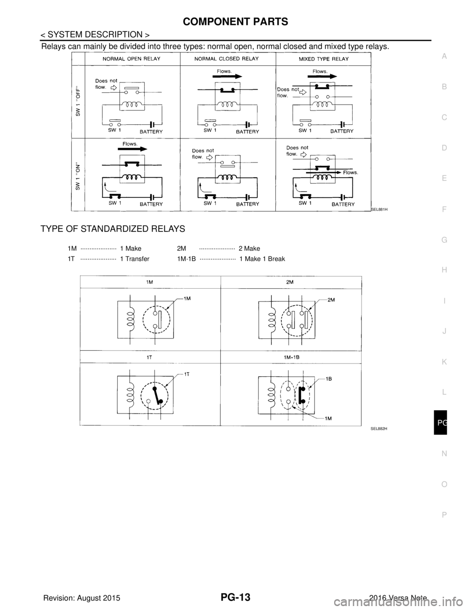
Relays can mainly be divided into three types: normal open, normal closed and mixed type relays.
TYPE OF STANDARDIZED RELAYS
SEL881H
1M ···················· 1 Make
2M ···················· 2 Make
1T ···················· 1 Transfer 1M·1B ···················· 1 Make 1 Break
SEL882H
Revision: August 2015 2016 Versa Note
cardiagn.com
Page 2636 of 3641

PG
HARNESSPG-49
< WIRING DIAGRAM >
C
DE
F
G H
I
J
K L
B A
O P
N
B3 F1 B/3 : Generator
D4 F28 — : Starter motor
B3 F2 — : Generator D3 F29 B/2 : Fuel injector no. 3 (Rear)
B4 F3 B/1 : A/C compressor D3 F30 B/2 : Fuel injector no. 4 (Rear)
B4 F4 — : Generator D1 F31 B/6 : Mass air flow sensor
B4 F5 — : Engine ground E1 F32 GR/2: Exhaust valve timing control solenoid
valve
E2 F6 GR/2 : Engine coolant temperature sensor F1 F33 W/6 : To E19
D1 F7 B/6 : Electric throttle control actuator B1 F34 GR/3: Ignition coil no.1 (With power
transistor)
E 1 F 8 W / 2 4 : To E 8 C 1 F 3 5 G R / 3: Ignition coil no.2 (With power
transistor)
F2 F9 GR/4 : Battery current sensor C1 F36 GR/3: Ignition coil no.3 (With power
transistor)
G 2 F 1 0 G R / 3 2 : E C M D 2 F 3 7 G R / 3: Ignition coil no.4 (With power
transistor)
G1 F11 BR/48 : ECM C4 F38 B/3 : Engine oil pressure sensor
D1 F12 BR/4 : Air fuel ratio (A/F) sensor 1 G3 F39 — : Fusible link box (Battery)
C3 F14 GR/2 : Knock sensor G3 F40 — : Fusible link box (Battery)
E1 F15 B/3 : Crankshaft position sensor (POS) G4 F41 B/3 : Output speed sensor
D4 F16 — : Engine ground F2 F42 W/12: IPDM E/R (Intelligent power distribution
module engine room)
B3 F17 B/2 : Fuel injector no. 1 (Front) F2 F43 W/12: IPDM E/R (Intelligent power distribution
module engine room)
C3 F18 B/2 : Fuel injector no. 2 (Front) F2 F44 B/48 : TCM (Transmission control module)
C3 F19 B/2 : Fuel injector no. 3 (Front) F4 F46 GR/22 : CVT unit
D3 F20 B/2 : Fuel injector no. 4 (Front) G4 F48 B/3 : Secondary speed sensor
D2 F21 B/3 : Camshaft position sensor G4 F50 B/3 : Primary speed sensor
C 1 F 2 2 G R / 2 : Evap canister purge volume control
solenoid valve F3 F52 B/10 : Transmission range switch
B 3 F 2 3 G R / 2 : Intake valve timing control solenoid
valve
B3 F53 B/2 : Fuel injector no. 1 (Rear)
E4 F24 G/3 : Park/neutral position (PNP) switch C3 F54 B/2 : Fuel injector no. 2 (Rear)
C4 F25 GR/2 : Engine oil temperature sensor G1 F55 GR/12 : To E55
C 3 F 2 6 W / 2 : C o n d e n s e r D 2 F 5 6 B / 3: Exhaust valve timing control position
sensor
D 3 F 2 7 — : S t a r t e r m o t o r D 3 F 5 9 — : E n g i n e g r o u n d
Revision: August 2015 2016 Versa Note
cardiagn.com
Page 2652 of 3641

PG
FUSE INSPECTIONPG-65
< BASIC INSPECTION >
C
DE
F
G H
I
J
K L
B A
O P
N
FUSE INSPECTION
How To CheckINFOID:0000000012433130
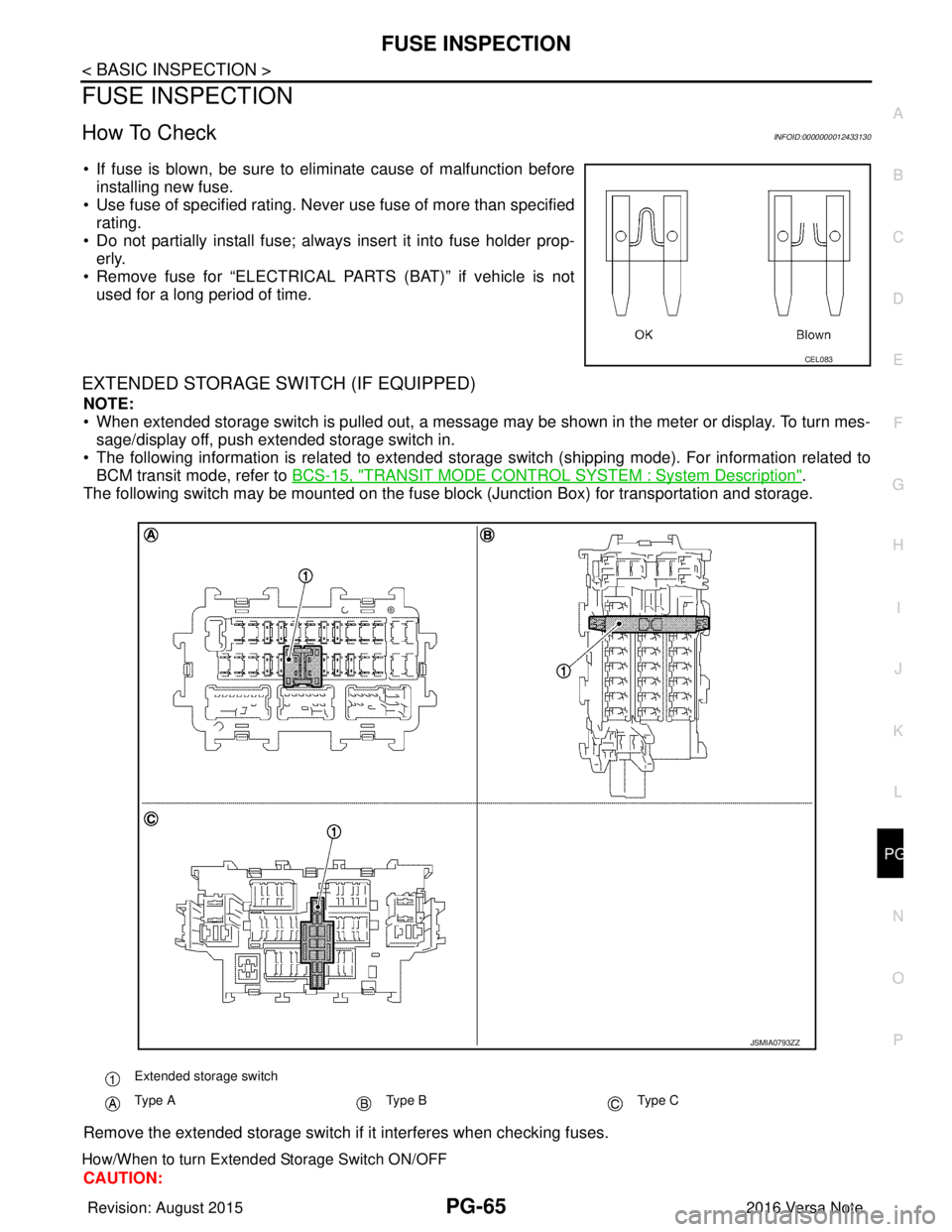
• If fuse is blown, be sure to eliminate cause of malfunction before
installing new fuse.
• Use fuse of specified rating. Never use fuse of more than specified
rating.
• Do not partially install fuse; always insert it into fuse holder prop- erly.
• Remove fuse for “ELECTRICAL PARTS (BAT)” if vehicle is not used for a long period of time.
EXTENDED STORAGE SWITCH (IF EQUIPPED)
NOTE:
• When extended storage switch is pulled out, a message may be shown in the\
meter or display. To turn mes-sage/display off, push extended storage switch in.
• The following information is related to extended storage switch (shipping mode). For information related to BCM transit mode, refer to BCS-15, "
TRANSIT MODE CONTROL SYSTEM : System Description".
The following switch may be mounted on the fuse block (Junction Box) for transportation and storage.
Remove the extended storage switch if it interferes when checking fuses.
How/When to turn Extended Storage Switch ON/OFF
CAUTION:
CEL083
Extended storage switch
Type AType BType C
JSMIA0793ZZ
Revision: August 2015 2016 Versa Note
cardiagn.com
Page 2654 of 3641

PG
FUSE INSPECTIONPG-67
< BASIC INSPECTION >
C
DE
F
G H
I
J
K L
B A
O P
N
How To Remove Extended Storage Switch
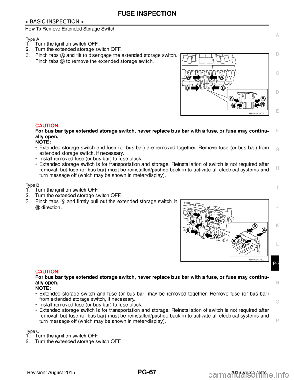
Type A
1. Turn the ignition switch OFF.
2. Turn the extended storage switch OFF.
3. Pinch tabs and tilt to disengage the extended storage switch.
Pinch tabs to remove the extended storage switch.
CAUTION:
For bus bar type extended storage switch, never replace bus bar with a fuse, or fuse may continu-
ally open.
NOTE:
• Extended storage switch and fuse (or bus bar) are removed together. Remove fuse (or bus bar) from extended storage switch, if necessary.
• Install removed fuse (or bus bar) to fuse block.
• Extended storage switch is for transportation and storage. Reinstallation of switch is not required after
removal, but fuse (or bus bar) must be reinstalled/ pushed back in to activate all electrical systems and
turn message off (which may be shown in meter/display).
Type B
1. Turn the ignition switch OFF.
2. Turn the extended storage switch OFF.
3. Pinch tabs and firmly pull out the extended storage switch in
direction.
CAUTION:
For bus bar type extended storage switch, never replace bus bar with a fuse, or fuse may continu-
ally open.
NOTE:
• Extended storage switch and fuse (or bus bar) may be removed together. Remove fuse (or bus bar) from extended storage switch, if necessary.
• Install removed fuse (or bus bar) to fuse block.
• Extended storage switch is for transportation and storage. Reinstallation of switch is not required after
removal, but fuse (or bus bar) must be reinstalled/ pushed back in to activate all electrical systems and
turn message off (which may be shown in meter/display).
Type C1. Turn the ignition switch OFF.
2. Turn the extended storage switch OFF.
JSMIA0476ZZ
JSMIA0477ZZ
Revision: August 2015 2016 Versa Note
cardiagn.com
Page 2655 of 3641

PG-68
< BASIC INSPECTION >
FUSE INSPECTION
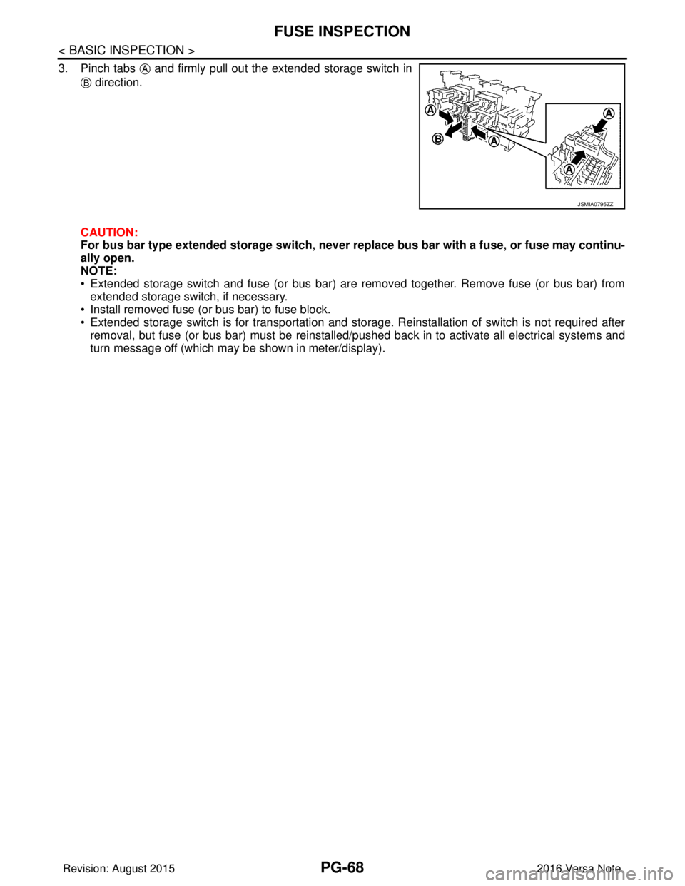
3. Pinch tabs and firmly pull out the extended storage switch in direction.
CAUTION:
For bus bar type extended storage switch, never replace bus bar with a fuse, or fuse may continu-
ally open.
NOTE:
• Extended storage switch and fuse (or bus bar) are removed together. Remove fuse (or bus bar) from extended storage switch, if necessary.
• Install removed fuse (or bus bar) to fuse block.
• Extended storage switch is for transportation and storage. Reinstallation of switch is not required after removal, but fuse (or bus bar) must be reinstalled/pushed back in to activate all electrical systems and
turn message off (which may be shown in meter/display).
JSMIA0795ZZ
Revision: August 2015 2016 Versa Note
cardiagn.com
Page 2668 of 3641

COMPONENT PARTSPWC-7
< SYSTEM DESCRIPTION >
C
DE
F
G H
I
J
L
M A
B
PWC
N
O P
Main Power Window And Door Lock/Unlock SwitchINFOID:0000000012431795
• Main power window and door lock/unlock switch controls all power windows.
• Main power window and door lock/unlock switch integrates UP/ DOWN switch, power window lock switch, and door lock/unlock
switch.
• Main power window and door lock/unlock switch controls the power window lock function.
Power Window SwitchINFOID:0000000012431796
• Each power window switch transmits UP/DOWN signal to eachmotor.
• Each power window switch transmits UP/DOWN signal from main power window and door lock/unlock switch to each motor.
Power Window MotorINFOID:0000000012431797
• Starts operation according to signals from main power window anddoor lock/unlock switch.
• Transmits front power window motor LH rotation as a pulse signal to main power window and door lock/unlock switch.
• Excepting power window motor for driver door, starts operation
according to signals from main power window and door lock/unlock
switch or each power window switches.
3. Front door switch LH • Inputs door open/close condition to BCM.
• Refer to DLK-19, "INTELLIGENT KEY SYSTEM : Door Switch" for detailed
installation location.
4. Rear power window switch LH Refer to PWC-7, "
Power Window Switch".
5. Front power window motor LH Refer to PWC-7, "
Power Window Motor".
6. Rear power window motor LH Refer to PWC-7, "
Power Window Motor".
No.
Component parts Function
ALKIA3203ZZ
ALKIA3204ZZ
JMKIA6528ZZ
Revision: August 2015 2016 Versa Note
cardiagn.com
Page 2670 of 3641

DIAGNOSIS SYSTEM (BCM) (WITH INTELLIGENT KEY SYSTEM)
PWC-9
< SYSTEM DESCRIPTION >
C
D E
F
G H
I
J
L
M A
B
PWC
N
O P
DIAGNOSIS SYSTEM (BCM) (WIT H INTELLIGENT KEY SYSTEM)
COMMON ITEM
COMMON ITEM : CONSULT Function (BCM - COMMON ITEM)INFOID:0000000012542484
APPLICATION ITEM
CONSULT performs the following functions via CAN communication with BCM.
SYSTEM APPLICATION
BCM can perform the following functions.
Direct Diagnostic Mode Description
ECU Identification The BCM part number is displayed.
Self Diagnostic Result The BCM self diagnostic results are displayed.
Data Monitor The BCM input/output data is displayed in real time.
Active Test The BCM activates outputs to test components.
Work support The settings for BCM functions can be changed.
Configuration • The vehicle specification can be read and saved.
• The vehicle specification can be written when replacing BCM.
CAN DIAG SUPPORT MNTR The result of transmit/receive diagnosis of CAN communication is displayed.
System Sub System Direct Diagnostic Mode
ECU Identification
Self Diagnostic Result
Data Monitor
Active Test
Work support
Configuration
CAN DIAG SUPPORT MNTR
Door lock
DOOR LOCK ×××
Rear window defogger REAR DEFOGGER ××
Warning chime BUZZER ××
Interior room lamp timer INT LAMP ×××
Exterior lamp HEAD LAMP ×××
Wiper and washer WIPER ×××
Turn signal and hazard warning lamps FLASHER ×××
Air conditioner AIR CONDITIONER ×
Intelligent Key system INTELLIGENT KEY ××××
Combination switch COMB SW ×
BCM BCM× × ×××
Immobilizer IMMU ××××
Interior room lamp battery saver BATTERY SAVER ×××
Vehicle security system THEFT ALM ××
RAP system RETAINED PWR ×
Signal buffer system SIGNAL BUFFER ×
TPMS AIR PRESSURE MONITOR ××××
Panic alarm system PANIC ALARM ×
Revision: August 2015 2016 Versa Note
cardiagn.com