2016 NISSAN NOTE trans
[x] Cancel search: transPage 1844 of 3641
SERVICE DATA AND SPECIFICATIONS (SDS)FAX-27
< SERVICE DATA AND SPECIFICATIONS (SDS)
CEF
G H
I
J
K L
M A
B
FA X
N
O P
SERVICE DATA AND SPECIFICATIONS (SDS)
SERVICE DATA AND SPECIFICATIONS (SDS)
Wheel BearingINFOID:0000000012431902
Drive ShaftINFOID:0000000012431903
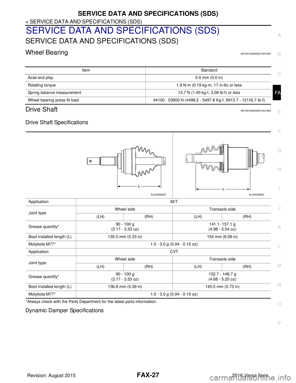
Drive Shaft Specifications
*Always check with the Parts Departme nt for the latest parts information.
Dynamic Damper Specifications
Item Standard
Axial end play 0.0 mm (0.0 in)
Rotating torque 1.9 N·m (0.19 kg-m, 17 in-lb) or less
Spring balance measurement 13.7 N (1.40 kg-f, 3.08 lb-f) or less
Wheel bearing press-fit load 44100 - 53900 N (4498.2 - 5497.8 Kg-f, 9913.7 - 12116.7 Ib-f)
Application M/T
Joint type Wheel side
Transaxle side
(LH) (RH) (LH)(RH)
Grease quantity* 90 - 100 g
(3.17 - 3.53 oz) 141.1- 157.1 g
(4.98 - 5.54 oz)
Boot installed length (L) 135.5 mm (5.33 in) 154 mm (6.06 in)
Molykote M77* 1.0 - 3.0 g (0.04 - 0.10 oz)
Application CVT
Joint type Wheel side
Transaxle side
(LH) (RH) (LH)(RH)
Grease quantity* 90 - 100 g
(3.17 - 3.53 oz) 132.7 - 148.7 g
(4.68 - 5.25 oz)
Boot installed length (L) 136.8 mm (5.39 in) 145.5 mm (5.73 in)
Molykote M77* 1.0 - 3.0 g (0.04 - 0.10 oz)
ALDIA0269ZZALDIA0268ZZ
Revision: August 2015 2016 Versa Note
cardiagn.com
Page 1846 of 3641
FSU-1
SUSPENSION
C
DF
G H
I
J
K L
M
SECTION FSU
A
B
FSU
N
O PCONTENTS
FRONT SUSPENSION
PRECAUTION ....... ........................................2
PRECAUTIONS .............................................. .....2
Precaution for Supplemental Restraint System
(SRS) "AIR BAG" and "SEAT BELT PRE-TEN-
SIONER" ............................................................. ......
2
Precaution for Procedure without Cowl Top Cover ......2
Precaution for Suspension ........................................2
PREPARATION ............................................3
PREPARATION .............................................. .....3
Special Service Tools .......................................... ......3
Commercial Service Tools ........................................3
SYMPTOM DIAGNOSIS ...............................5
NOISE, VIBRATION AND HARSHNESS
(NVH) TROUBLESHOOTING ........................ .....
5
NVH Troubleshooting Chart ................................ ......5
PERIODIC MAINTENANCE ..........................6
FRONT SUSPENSION ASSEMBLY .............. .....6
Inspection ............................................................ ......6
WHEEL ALIGNMENT ..........................................7
Inspection ............................................................ ......7
Adjustment ................................................................8
REMOVAL AND INSTALLATION ................9
FRONT COIL SPRING AND STRUT ............. .....9
Exploded View .................................................... ......9
Removal and Installation ...........................................9
TRANSVERSE LINK .........................................10
Exploded View ..................................................... ....10
Removal and Installation .........................................10
Inspection ................................................................10
FRONT STABILIZER ........................................12
Exploded View .........................................................12
Removal and Installation .........................................12
Inspection ................................................................13
UNIT REMOVAL AND INSTALLATION ......14
FRONT SUSPENSION MEMBER .....................14
Exploded View ..................................................... ....14
Removal and Installation .........................................14
Inspection ................................................................15
UNIT DISASSEMBLY AND ASSEMBLY ....16
FRONT COIL SPRING AND STRUT ................16
Exploded View ..................................................... ....16
Disassembly and Assembly .....................................16
Inspection ................................................................19
Disposal ...................................................................19
SERVICE DATA AND SPECIFICATIONS
(SDS) ............... .......................................... ...
20
SERVICE DATA AND SPECIFICATIONS
(SDS) .................................................................
20
Wheel Alignment (Unladen*1) ..................................20
Ball Joint .............................................................. ....20
Wheelarch Height (Unladen*) ..................................21
Revision: August 2015 2016 Versa Note
cardiagn.com
Page 1851 of 3641
FSU-6
< PERIODIC MAINTENANCE >
FRONT SUSPENSION ASSEMBLY
PERIODIC MAINTENANCE
FRONT SUSPENSION ASSEMBLY
InspectionINFOID:0000000012430300
COMPONENT PART
Check the mount conditions (looseness, backlash) of each component. Verify the component conditions
(wear, damage) are normal.
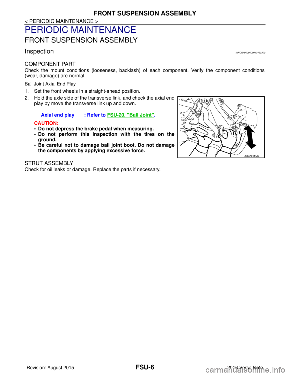
Ball Joint Axial End Play
1. Set the front wheels in a straight-ahead position.
2. Hold the axle side of the tran sverse link, and check the axial end
play by move the transverse link up and down.
CAUTION:
• Do not depress the brake pedal when measuring.
• Do not perform this inspect ion with the tires on the
ground.
• Be careful not to damage ball joint boot. Do not damage the components by applying excessive force.
STRUT ASSEMBLY
Check for oil leaks or damage. Replace the parts if necessary.Axial end play : Refer to
FSU-20, "
Ball Joint".
JSEIA0444ZZ
Revision: August 2015 2016 Versa Note
cardiagn.com
Page 1855 of 3641
FSU-10
< REMOVAL AND INSTALLATION >
TRANSVERSE LINK
TRANSVERSE LINK
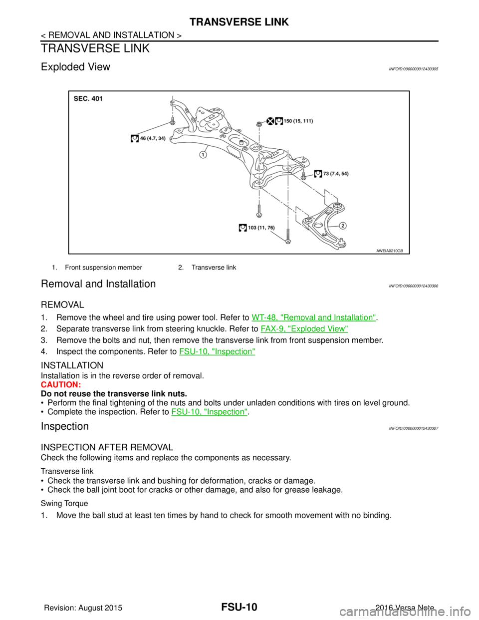
Exploded ViewINFOID:0000000012430305
Removal and InstallationINFOID:0000000012430306
REMOVAL
1. Remove the wheel and tire using power tool. Refer to WT-48, "Removal and Installation".
2. Separate transverse link from steering knuckle. Refer to FA X - 9 , "
Exploded View"
3. Remove the bolts and nut, then remove the transverse link from front suspension member.
4. Inspect the components. Refer to FSU-10, "
Inspection"
INSTALLATION
Installation is in the reverse order of removal.
CAUTION:
Do not reuse the transverse link nuts.
• Perform the final tightening of the nuts and bolts under unladen conditions with tires on level ground.
• Complete the inspection. Refer to FSU-10, "
Inspection".
InspectionINFOID:0000000012430307
INSPECTION AFTER REMOVAL
Check the following items and replace the components as necessary.
Transverse link
• Check the transverse link and bushing for deformation, cracks or damage.
• Check the ball joint boot for cracks or other damage, and also for grease leakage.
Swing Torque
1. Move the ball stud at least ten times by hand to check for smooth movement with no binding.
1. Front suspension member2. Transverse link
AWEIA0210GB
Revision: August 2015 2016 Versa Note
cardiagn.com
Page 1856 of 3641
TRANSVERSE LINKFSU-11
< REMOVAL AND INSTALLATION >
C
DF
G H
I
J
K L
M A
B
FSU
N
O P
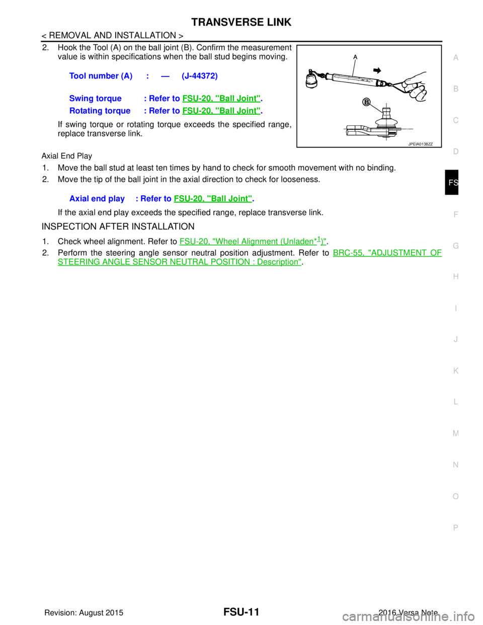
2. Hook the Tool (A) on the ball joint (B). Confirm the measurement value is within specifications when the ball stud begins moving.
If swing torque or rotating torque exceeds the specified range,
replace transverse link.
Axial End Play
1. Move the ball stud at least ten times by hand to check for smooth movement with no binding.
2. Move the tip of the ball joint in the axial direction to check for looseness.
If the axial end play exceeds the specified range, replace transverse link.
INSPECTION AFTER INSTALLATION
1. Check wheel alignment. Refer to FSU-20, "Wheel Alignment (Unladen*1)".
2. Perform the steering angle sensor neutral position adjustment. Refer to BRC-55, "
ADJUSTMENT OF
STEERING ANGLE SENSOR NEUTRAL POSITION : Description".
Tool number (A) : — (J-44372)
Swing torque : Refer to
FSU-20, "
Ball Joint".
Rotating torque : Refer to FSU-20, "
Ball Joint".
JPEIA0138ZZ
Axial end play : Refer to FSU-20, "Ball Joint".
Revision: August 2015 2016 Versa Note
cardiagn.com
Page 1859 of 3641
FSU-14
< UNIT REMOVAL AND INSTALLATION >
FRONT SUSPENSION MEMBER
UNIT REMOVAL AND INSTALLATION
FRONT SUSPENSION MEMBER
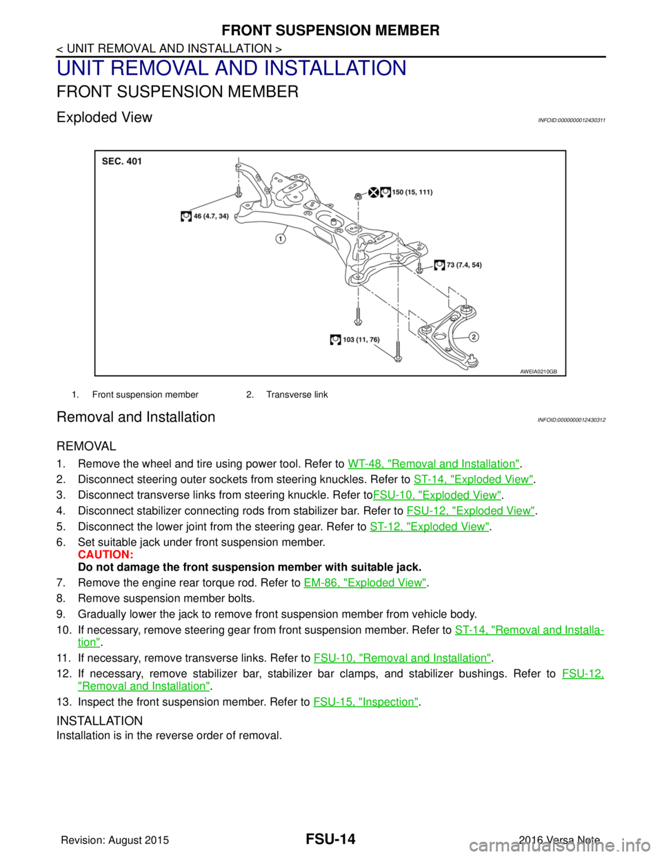
Exploded ViewINFOID:0000000012430311
Removal and InstallationINFOID:0000000012430312
REMOVAL
1. Remove the wheel and tire using power tool. Refer to WT-48, "Removal and Installation".
2. Disconnect steering outer sockets from steering knuckles. Refer to ST-14, "
Exploded View".
3. Disconnect transverse links from steering knuckle. Refer to FSU-10, "
Exploded View".
4. Disconnect stabilizer connecting rods from stabilizer bar. Refer to FSU-12, "
Exploded View".
5. Disconnect the lower joint from the steering gear. Refer to ST-12, "
Exploded View".
6. Set suitable jack under front suspension member. CAUTION:
Do not damage the front suspensi on member with suitable jack.
7. Remove the engine rear torque rod. Refer to EM-86, "
Exploded View".
8. Remove suspension member bolts.
9. Gradually lower the jack to remove front suspension member from vehicle body.
10. If necessary, remove steering gear from front suspension member. Refer to ST-14, "
Removal and Installa-
tion".
11. If necessary, remove transverse links. Refer to FSU-10, "
Removal and Installation".
12. If necessary, remove stabilizer bar, stabilizer bar clamps, and stabilizer bushings. Refer to FSU-12,
"Removal and Installation".
13. Inspect the front suspension member. Refer to FSU-15, "
Inspection".
INSTALLATION
Installation is in the reverse order of removal.
1. Front suspension member2. Transverse link
AWEIA0210GB
Revision: August 2015 2016 Versa Note
cardiagn.com
Page 1879 of 3641
FUEL TANKFL-13
< REMOVAL AND INSTALLATION >
C
DE
F
G H
I
J
K L
M A
FL
NP
O
17. If replacing the fuel tank, remove the fuel level sensor unit, fuel filter and fuel pump assembly to transfer to
the new fuel tank.
CAUTION:
Do not reuse O-ring.
INSTALLATION
Installation is in the reverse order of removal.
Fuel Filler Hose
• Insert fuel filler hose to the length below.
• Be sure hose clamp is not placed on swelled area of fuel filler tube.
• Install fuel filler hose to fuel t ank, paying attention to install mark.
EVAP Hose
1. Check connections for damage or foreign material.
2. Align the matching side connection part with the center of shaft, and insert connector straight until a "click"
sound is heard.
InspectionINFOID:0000000012432114
INSPECTION AFTER INSTALLATION
Use the following procedure to check for fuel leaks.
1. Turn ignition switch “ON” (with engine stopped), then check fuel system connections for leaks by applying
fuel pressure to fuel piping.
2. Start engine and let it idle and check there are no fuel leaks at the fuel system connections.
Fuel filler hose : 35 mm (1.38 in)
Vent hose : 25 mm (0.98 in)
Revision: August 2015
2016 Versa Note
cardiagn.com
Page 1889 of 3641
GI-1
GENERAL INFORMATION
C
DE
F
G H
I
J
K L
M B
GI
SECTION GI
N
O P
CONTENTS
GENERAL INFORMATION
HOW TO USE THIS MANU AL ......................3
HOW TO USE THIS MANUAL ....................... .....3
Description .......................................................... ......3
Terms ........................................................................3
Units ..........................................................................3
Contents ....................................................................3
Relation between Illustrations and Descriptions .......4
Components ..............................................................4
HOW TO FOLLOW TROUBLE DIAGNOSES .....6
Description ................................................................6
How to Follow Test Groups in Trouble Diagnosis ......6
Key to Symbols Signifying Measurements or Pro-
cedures ............................................................... ......
7
HOW TO READ WIRING DIAGRAMS ................9
Connector Symbols ............................................. ......9
Sample/Wiring Diagram -Example- .........................10
Connector Information .............................................12
ABBREVIATIONS .......................................... ....14
Abbreviation List .................................................. ....14
TIGHTENING TORQUE OF STANDARD
BOLTS ................................................................
19
Description .......................................................... ....19
Tightening Torque Table (New Standard Includ-
ed) ...........................................................................
19
RECOMMENDED CHEMICAL PRODUCTS
AND SEALANTS ................................................
22
Recommended Chemical Products and Sealants ....22
PRECAUTION ..............................................23
PRECAUTIONS .............................................. ....23
Description .......................................................... ....23
Precaution for Supplemental Restraint System
(SRS) "AIR BAG" and "SEAT BELT PRE-TEN-
SIONER" .................................................................
23
Procedures without Cowl Top Cover .......................23
Cautions in Removing Battery Terminal and AV
Control Unit (Models with AV Control Unit) .............
23
General Precautions ............................................ ....24
Three Way Catalyst .................................................25
Fuel ..........................................................................25
Multiport Fuel Injection System or Engine Control
System .....................................................................
26
Hoses ......................................................................26
Engine Oils ..............................................................27
Air Conditioning .......................................................27
LIFTING POINT .................................................28
Special Service Tool ................................................28
Garage Jack and Safety Stand ................................28
2-Pole Lift ................................................................29
Board-on Lift ............................................................30
TOW TRUCK TOWING .....................................31
Tow Truck Towing ...................................................31
Vehicle Recovery (Freeing a Stuck Vehicle) ...........31
VEHICLE INFORMATION ...........................33
IDENTIFICATION INFORMATION ....................33
Model Variation .................................................... ....33
Identification Number ...............................................34
Identification Plate ...................................................35
Engine Serial Number .............................................36
CVT Number ............................................................36
Manual Transaxle Number ......................................36
Dimensions ..............................................................36
Wheels & Tires ........................................................37
BASIC INSPECTION ...................................38
SERVICE INFORMATION FOR ELECTRICAL
INCIDENT ..........................................................
38
Work Flow ............................................................ ....38
Control Units and Electrical Parts ............................38
How to Check Terminal ...........................................39
Intermittent Incident ............................................. ....42
Circuit Inspection .....................................................44
Revision: August 2015 2016 Versa Note
cardiagn.com