2016 NISSAN NOTE trans
[x] Cancel search: transPage 1919 of 3641
TOW TRUCK TOWINGGI-31
< PRECAUTION >
C
DE
F
G H
I
J
K L
M B
GI
N
O PTOW TRUCK TOWING
To w T r u c k To w i n gINFOID:0000000012433173
CAUTION:
• Never tow a CVT model with the rear wheels raised and the front wheels on the ground. This may
cause serious and expensive damage to the transaxle. If it is necessary to tow the vehicle with the
rear wheels raised, always use towin g dollies under the front wheels.
• Never tow a CVT model from the rear (that is b ackward) with four wheels on the ground. This may
cause serious and expensive damage to the transaxle.
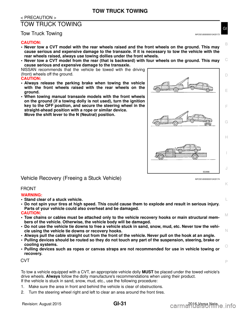
NISSAN recommends that the vehicle be towed with the driving
(front) wheels off the ground.
CAUTION:
• Always release the parking br ake when towing the vehicle
with the front wheels raised with the rear wheels on the
ground.
• When towing manual transaxle models with the front wheels on the ground (if a towing dolly is not used), turn the ignition
key to the OFF position, and secu re the steering wheel in the
straight-ahead position with a rope or similar device.
Move the shift lever to th e N (Neutral) position.
Vehicle Recovery (Freeing a Stuck Vehicle)INFOID:0000000012433174
FRONT
WARNING:
• Stand clear of a stuck vehicle.
• Do not spin your tires at high speed. This could cause them to explode and result in serious injury.
Parts of your vehicle could also overheat and be damaged.
CAUTION:
• Tow chains or cables must be attached only to the vehicle recovery hooks or main structural mem-
bers of the vehicle. Otherwise, the vehicle body will be damaged.
• Do not use the vehicle tie downs to free a vehicle stuck in sand, snow, mud, etc. Never tow the vehi-
cle using the vehicle tie downs or recovery hooks.
• Always pull the cable straight out from the front of the vehicle. Never pull on the hook at an angle.
• Pulling devices should be routed so they do not touch any part of the suspension, steering, brake or
cooling systems.
• Pulling devices such as ropes or canvas straps ar e not recommended for use in vehicle towing or
recovery.
CVT
To tow a vehicle equipped with a CVT, an appropriate vehicle dolly MUST be placed under the towed vehicle's
drive wheels. Always follow the dolly manufacture's re commendations when using their product.
If the vehicle is stuck in sand, snow , mud, etc., use the following procedure:
1. Make sure the area in front and behind the vehicle is clear of obstructions.
2. Turn the steering wheel right and left to clear an area around the front tires.
SGI986
Revision: August 2015 2016 Versa Note
cardiagn.com
Page 1921 of 3641
IDENTIFICATION INFORMATIONGI-33
< VEHICLE INFORMATION >
C
DE
F
G H
I
J
K L
M B
GI
N
O PVEHICLE INFORMATION
IDENTIFICATION INFORMATION
Model VariationINFOID:0000000012433175
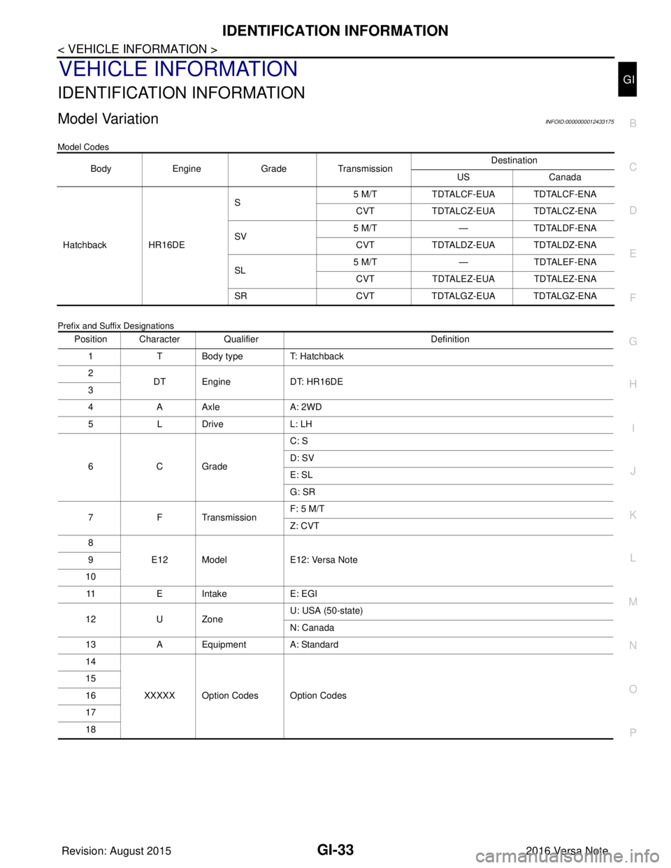
Model Codes
Prefix and Suffix Designations
Body Engine GradeTransmission Destination
US Canada
Hatchback HR16DE S
5 M/T
TDTALCF-EUA TDTALCF-ENA
CVT TDTALCZ-EUA TDTALCZ-ENA
SV 5 M/T
—TDTALDF-ENA
CVT TDTALDZ-EUA TDTALDZ-ENA
SL 5 M/T
—TDTALEF-ENA
CVT TDTALEZ-EUA TDTALEZ-ENA
SR CVTTDTALGZ-EUA TDTALGZ-ENA
Position Character Qualifier Definition
1 T Body type T: Hatchback
2 DT Engine DT: HR16DE
3
4 A Axle A: 2WD
5LD riv e L : L H
6CG ra d e C: S
D: SV
E: SL
G: SR
7 F Transmission F: 5 M/T
Z: CVT
8 E12 Model E12: Versa Note
9
10 11 E I n t a k e E : E G I
12 U Zone U: USA (50-state)
N: Canada
13 A Equipment A: Standard
14
XXXXX Option Codes Option Codes
15
16
17
18
Revision: August 2015
2016 Versa Note
cardiagn.com
Page 1924 of 3641
GI-36
< VEHICLE INFORMATION >
IDENTIFICATION INFORMATION
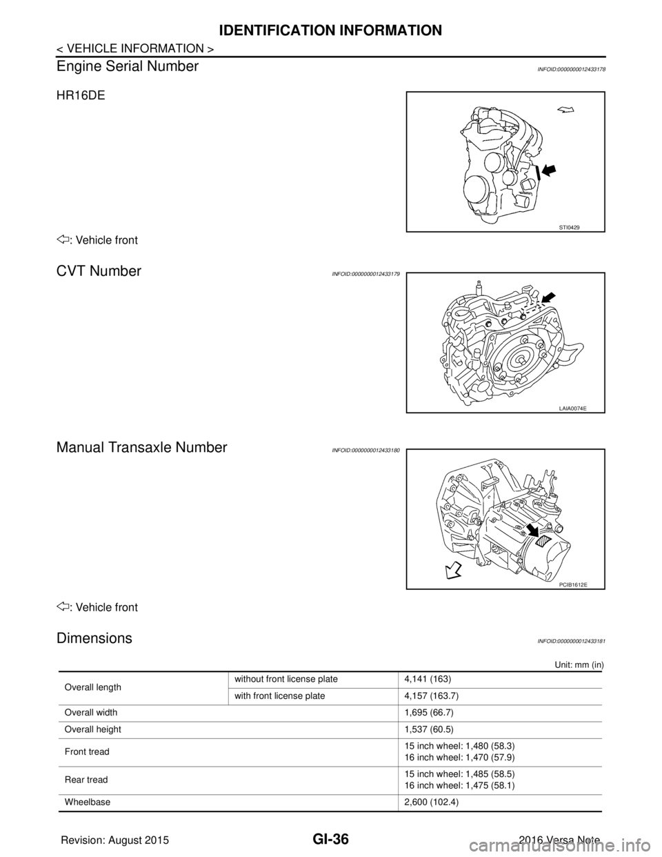
Engine Serial Number
INFOID:0000000012433178
HR16DE
: Vehicle front
CVT NumberINFOID:0000000012433179
Manual Transaxle NumberINFOID:0000000012433180
: Vehicle front
DimensionsINFOID:0000000012433181
Unit: mm (in)
STI0429
LAIA0074E
PCIB1612E
Overall length without front license plate 4,141 (163)
with front license plate
4,157 (163.7)
Overall width 1,695 (66.7)
Overall height 1,537 (60.5)
Front tread 15 inch wheel: 1,480 (58.3)
16 inch wheel: 1,470 (57.9)
Rear tread 15 inch wheel: 1,485 (58.5)
16 inch wheel: 1,475 (58.1)
Wheelbase 2,600 (102.4)
Revision: August 2015 2016 Versa Note
cardiagn.com
Page 1926 of 3641
GI-38
< BASIC INSPECTION >
SERVICE INFORMATION FOR ELECTRICAL INCIDENT
BASIC INSPECTION
SERVICE INFORMATION FOR ELECTRICAL INCIDENT
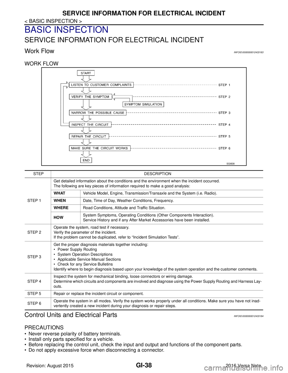
Work FlowINFOID:0000000012433183
WORK FLOW
Control Units and Electrical PartsINFOID:0000000012433184
PRECAUTIONS
• Never reverse polarity of battery terminals.
• Install only parts specified for a vehicle.
• Before replacing the control unit, check the i nput and output and functions of the component parts.
• Do not apply excessive force when disconnecting a connector.
SGI838
STEP DESCRIPTION
STEP 1 Get detailed information about the conditions and the environment when the incident occurred.
The following are key pieces of information required to make a good analysis:
WHAT
Vehicle Model, Engine, Transmission/Transaxle and the System (i.e. Radio).
WHEN Date, Time of Day, Weather Conditions, Frequency.
WHERE Road Conditions, Altitude and Traffic Situation.
HOW System Symptoms, Operating Conditions
(Other Components Interaction).
Service History and if any After Market Accessories have been installed.
STEP 2 Operate the system, road test if necessary.
Verify the parameter of the incident.
If the problem cannot be duplicated, refer to “Incident Simulation Tests”.
STEP 3 Get the proper diagnosis materials together including:
• Power Supply Routing
• System Operation Descriptions
• Applicable Service Manual Sections
• Check for any Service Bulletins
Identify where to begin diagnosis based upon your knowledge of the system operation and the customer comments.
STEP 4 Inspect the system for mechanical binding, loose connectors or wiring damage.
Determine which circuits and components are involved and diagnose using the Power Supply Routing and Harness Lay-
outs.
STEP 5 Repair or replace the incident circuit or component.
STEP 6 Operate the system in all modes. Verify the system works properly under all conditions. Make sure you have not inad-
vertently created a new incident during your diagnosis or repair steps.
Revision: August 2015
2016 Versa Note
cardiagn.com
Page 1927 of 3641
SERVICE INFORMATION FOR ELECTRICAL INCIDENTGI-39
< BASIC INSPECTION >
C
DE
F
G H
I
J
K L
M B
GI
N
O P
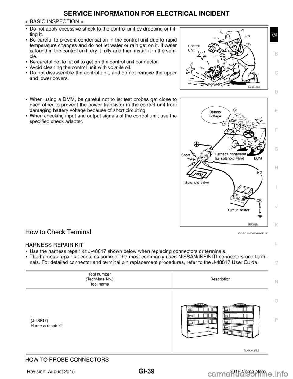
• Do not apply excessive shock to the control unit by dropping or hit- ting it.
• Be careful to prevent condensation in the control unit due to rapid
temperature changes and do not let water or rain get on it. If water
is found in the control unit, dry it fully and then install it in the vehi-
cle.
• Be careful not to let oil to get on the control unit connector.
• Avoid cleaning the control unit with volatile oil.
• Do not disassemble the control unit, and do not remove the upper and lower covers.
• When using a DMM, be careful not to let test probes get close to each other to prevent the power transistor in the control unit from
damaging battery voltage because of short circuiting.
• When checking input and output signals of the control unit, use the specified check adapter.
How to Check TerminalINFOID:0000000012433185
HARNESS REPAIR KIT
• Use the harness repair kit J-48817 shown below when replacing connectors or terminals.
• The harness repair kit contains some of the most commonly used NISSAN/INFINITI connectors and termi-nals. For detailed connector and terminal pin replac ement procedures, refer to the J-48817 User Guide.
HOW TO PROBE CONNECTORS
SAIA0255E
SEF348N
Tool number
(TechMate No.) Tool name Description
-
(J-48817)
Harness repair kit
ALAIA0137ZZ
Revision: August 2015 2016 Versa Note
cardiagn.com
Page 1938 of 3641
GI-50
< BASIC INSPECTION >
CONSULT/GST CHECKING SYSTEM
CONSULT/GST CHECKING SYSTEM
DescriptionINFOID:0000000012433188
NOTE:
This vehicle is diagnosed using the CONSULT-III plus.
• When CONSULT is connected with a data link connector equippedon the vehicle side, it will communicate with the control unit
equipped in the vehicle and then enable various kinds of diagnos-
tic tests.
• Refer to “CONSULT-III plus Operation Manual” for more informa- tion.
Function and System ApplicationINFOID:0000000012433189
x: Applicable
1: With continuously variable transmission 1 : Hood release handle
2 : Data link connector
ALAIA0095ZZ
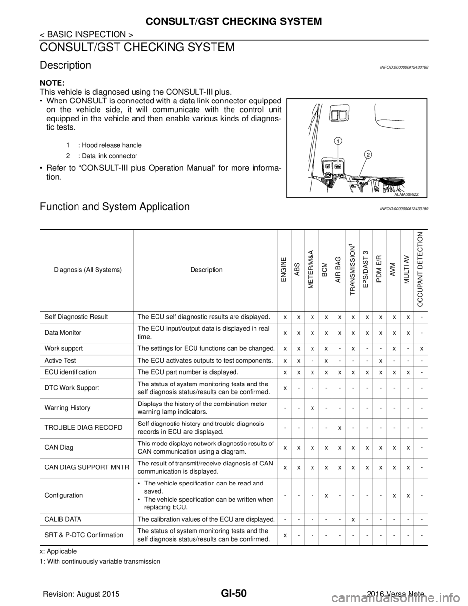
Diagnosis (All Systems)
Description
ENGINE
ABS
METER/M&A BCM
AIR BAG
TRANSMISSION
1
EPS/DAST 3 IPDM E/R AV M
MULTI AV
OCCUPANT DETECTION
Self Diagnostic Result The ECU self diagnostic results are displayed. x x x x x x x x x x -
Data Monitor The ECU input/output data is displayed in real
time. xxxxxxxxxx -
Work support The settings for ECU functions can be changed. x x x x - x - - x - x
Active Test The ECU activates outputs to test components. x x - x - - - x - - -
ECU identification The ECU part number is displayed. xxxxxxxxxx -
DTC Work Support The status of system monitoring tests and the
self diagnosis status/results can be confirmed. x----------
Warning History Displays the history of the combination meter
warning lamp indicators.
--x--------
TROUBLE DIAG RECORD Self diagnostic history and trouble diagnosis
records in ECU are displayed. ----x------
CAN Diag This mode displays network diagnostic results of
CAN communication using a diagram. xxxxxxxxxx -
CAN DIAG SUPPORT MNTR The result of transmit/receive diagnosis of CAN
communication is displayed.
xxxxxxxxxx -
Configuration • The vehicle specification can be read and
saved.
• The vehicle specification can be written when
replacing ECU. ---x----xx-
CALIB DATA The calibration values of the ECU are displayed. - - - - - x - - - - -
SRT & P-DTC Confirmation The status of system monitoring tests and the
self diagnosis status/results can be confirmed. x----------
Revision: August 2015
2016 Versa Note
cardiagn.com
Page 1948 of 3641

GW-8
< SYMPTOM DIAGNOSIS >
SQUEAK AND RATTLE TROUBLE DIAGNOSES
1. Loose harness or harness connectors.
2. Front console map/reading lamp lens loose.
3. Loose screws at console attachment points.
SEATS
When isolating seat noise it's important to note the position the seat is in and the load placed on the seat when
the noise is present. These conditions should be duplicated when verifying and isolating the cause of the
noise.
Cause of seat noise include:
1. Headrest rods and holder
2. A squeak between the seat pad cushion and frame
3. The rear seatback lock and bracket
These noises can be isolated by moving or pressing on the suspected components while duplicating the con-
ditions under which the noise occurs. Most of thes e incidents can be repaired by repositioning the component
or applying urethane tape to the contact area.
UNDERHOOD
Some interior noise may be caused by components under the hood or on the engine wall. The noise is then
transmitted into the passenger compartment.
Causes of transmitted underhood noise include:
1. Any component installed to the engine wall
2. Components that pass through the engine wall
3. Engine wall mounts and connectors
4. Loose radiator installation pins
5. Hood bumpers out of adjustment
6. Hood striker out of adjustment
These noises can be difficult to isolate since they cannot be reached from the interior of the vehicle. The best
method is to secure, move or insulate one component at a time and test drive the vehicle. Also, engine rpm or
load can be changed to isolate the noise. Repairs can usually be made by moving, adjusting, securing, or
insulating the component causing the noise.
Revision: August 2015 2016 Versa Note
cardiagn.com
Page 1977 of 3641
![NISSAN NOTE 2016 Service Repair Manual COMPONENT PARTSHAC-9
< SYSTEM DESCRIPTION > [MANUAL AIR CONDITIONING]
C
D
E
F
G H
J
K L
M A
B
HAC
N
O P
SYSTEM DESCRIPTION
COMPONENT PARTS
Component Parts LocationINFOID:0000000012430716
A. RH front o NISSAN NOTE 2016 Service Repair Manual COMPONENT PARTSHAC-9
< SYSTEM DESCRIPTION > [MANUAL AIR CONDITIONING]
C
D
E
F
G H
J
K L
M A
B
HAC
N
O P
SYSTEM DESCRIPTION
COMPONENT PARTS
Component Parts LocationINFOID:0000000012430716
A. RH front o](/manual-img/5/57363/w960_57363-1976.png)
COMPONENT PARTSHAC-9
< SYSTEM DESCRIPTION > [MANUAL AIR CONDITIONING]
C
D
E
F
G H
J
K L
M A
B
HAC
N
O P
SYSTEM DESCRIPTION
COMPONENT PARTS
Component Parts LocationINFOID:0000000012430716
A. RH front of engine compartment B. Behind LH side of front fascia No. Component Description
1. ECM The ECM sends a compressor ON request to the IPDM E/R based on the status of engine
operation and load as well as refrigerant pressure information. If all the conditions are met for
A/C operation, the ECM transmits the compressor ON request to the IPDM E/R.
2. IPDM E/R A/C relay is integrated in IPDM E/R. IPDM
E/R operates A/C relay when receiving A/C com-
pressor request signal from ECM via CAN communication line.
3. A/C compressor Vaporized refrigerant is drawn into the A/C compressor from the evaporator, where it is com-
pressed to a high pressure, high temperature vapor. The hot, compressed vapor is then dis-
charged to the condenser.
4. Refrigerant pressure sensor Refer to EC-27, "
Refrigerant Pressure Sensor".
ALIIA0811ZZ
Revision: August 2015 2016 Versa Note
cardiagn.com