2016 NISSAN NOTE trans
[x] Cancel search: transPage 1818 of 3641
FAX-1
TRANSMISSION & DRIVELINE
CEF
G H
I
J
K L
M
SECTION FA X
A
B
FA X
N
O P
CONTENTS
FRONT AXLE
PRECAUTION ....... ........................................2
PRECAUTIONS .............................................. .....2
Precaution for Supplemental Restraint System
(SRS) "AIR BAG" and "SEAT BELT PRE-TEN-
SIONER" ............................................................. ......
2
Precaution for Drive Shaft .........................................2
Precautions for Wheel Hub and Knuckle ..................2
PREPARATION ............................................3
PREPARATION .............................................. .....3
Special Service Tools .......................................... ......3
Commercial Service Tools ........................................4
SYMPTOM DIAGNOSIS ...............................6
NOISE, VIBRATION AND HARSHNESS
(NVH) TROUBLESHOOTING ........................ .....
6
NVH Troubleshooting Chart ................................ ......6
PERIODIC MAINTENANCE ..........................7
FRONT WHEEL HUB AND KNUCKLE ......... .....7
Inspection ............................................................ ......7
FRONT DRIVE SHAFT ........................................8
Inspection ............................................................ ......8
REMOVAL AND INSTALLATION ................9
FRONT WHEEL HUB AND KNUCKLE ......... .....9
Exploded View ..................................................... .....9
Removal and Installation ..........................................9
Disassembly and Assembly .....................................11
Inspection ................................................................13
FRONT DRIVE SHAFT BOOT ..........................14
Exploded View .........................................................14
WHEEL SIDE ......................................................... ....14
WHEEL SIDE : Removal and Installation ................15
TRANSAXLE SIDE ................................................ ....18
TRANSAXLE SIDE : Removal and Installation .......18
Inspection ............................................................ ....18
FRONT DRIVE SHAFT .....................................19
Exploded View .........................................................19
Removal and Installation .........................................19
UNIT DISASSEMBLY AND ASSEMBLY ....21
FRONT DRIVE SHAFT .....................................21
Exploded View ..................................................... ....21
Disassembly and Assembly .....................................22
SERVICE DATA AND SPECIFICATIONS
(SDS) ............... .......................................... ...
27
SERVICE DATA AND SPECIFICATIONS
(SDS) .................................................................
27
Wheel Bearing ..................................................... ....27
Drive Shaft ...............................................................27
Revision: August 2015 2016 Versa Note
cardiagn.com
Page 1827 of 3641
FAX-10
< REMOVAL AND INSTALLATION >
FRONT WHEEL HUB AND KNUCKLE
6. Separate the drive shaft from the wheel hub by lightly tapping the end of the drive shaft using a suitable
tool and a wood block.
NOTE:
Use suitable puller if wheel hub and drive shaft cannot be separated after performing the above proce-
dure.
7. Remove wheel hub lock nut.
8. Remove the nut and separate the steering out er socket from steering knuckle. Refer to ST-14, "
Exploded
View".
9. Remove the nuts and bolts, then separate the steering knuckle from strut. Refer to FA X - 9 , "
Removal and
Installation".
10. Suspend the drive shaft with suitable wire. CAUTION:
• Do not place drive shaft joint at an extreme angle. Also be careful not to overextend slide joint.
• Do not allow drive shaft to hang down withou t support for joint sub-assembly, shaft and the
other parts.
11. Remove transverse link outer nut and bolt. Remove steering knuckle from transverse link.
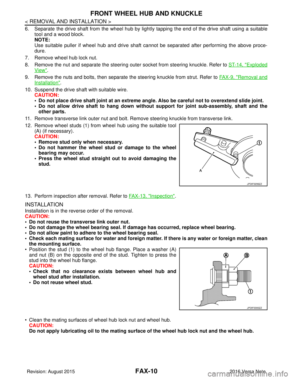
12. Remove wheel studs (1) from wheel hub using the suitable tool (A) (if necessary).
CAUTION:
• Remove stud only when necessary.
• Do not hammer the wheel stud or damage to the wheelbearing may occur.
• Press the wheel stud straight out to avoid damaging the stud.
13. Perform inspection after removal. Refer to FAX-13, "
Inspection".
INSTALLATION
Installation is in the reverse order of the removal.
CAUTION:
• Do not reuse the transverse link outer nut.
• Do not damage the wheel bearing seal. If damage has occurred, replace wheel bearing.
• Do not allow paint to adhere to the wheel bearing seal.
• Check each mating surface for water and foreign matter. If there is any water or foreign matter, clean
the mounting surface.
• Position the stud (1) to the wheel hub flange. Place a washer (A) and nut (B) on the opposite end of the stud. Tighten to press the
stud into the wheel hub flange.
CAUTION:
• Check that no clearance exists between wheel hub andwheel stud after installation.
• Do not reuse wheel stud.
• Clean the mating surfaces of wheel hub lock nut and wheel hub. CAUTION:
Do not apply lubricatin g oil to the mating surface of the wh eel hub lock nut and the wheel hub.
JPDIF0299ZZ
JPDIF0300ZZ
Revision: August 2015 2016 Versa Note
cardiagn.com
Page 1830 of 3641
FRONT WHEEL HUB AND KNUCKLEFAX-13
< REMOVAL AND INSTALLATION >
CEF
G H
I
J
K L
M A
B
FA X
N
O P
5. Perform inspection after assembly. Refer to FAX-13, "Inspection".
InspectionINFOID:0000000012431893
INSPECTION AFTER REMOVAL
Check the following items, and replace the part if necessary.
• Check components for deformation, cracks, and other damage.
• Check boots of transverse link and steering outer so cket ball joint for breakage, axial end play, and swing
torque. Refer to FSU-10, "
Inspection" and FSU-20, "Ball Joint".
INSPECTION AFTER DISASSEMBLY
Wheel Hub
• Check wheel hub for cracks (with magnetic exploration or dye testing). Replace if necessary.
Steering Knuckle
• Check steering knuckle for deformation, cracks, and other damage. Replace if any non-standard conditions
are found.
Snap Rings
• Check snap ring for wear or cracks. Replace if necessary.
INSPECTION AFTER ASSEMBLY
Check wheel bearing rotating torque as per the following instructions.
NOTE:
The adequacy of turning torque can be judged from a measurement value by a spring balancer.
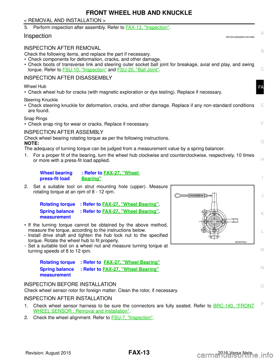
1. For a proper fit of the bearing, turn the wheel hub clockwise and counterclockwise, respectively, 10 times
or more with a press-fit load applied.
2. Set a suitable tool on strut mounting hole (upper). Measure rotating torque at an rpm of 8 - 12 rpm.
• If the turning torque cannot be obtained by the above method, measure the torque, according to the instructions below.
- Install drive shaft and tighten the hub lock nut to the specified
torque. Rotate the wheel hub to fit properly.
- Set a suitable tool on a wheel nut and measure turning torque at turning speeds of 8 to 12 rpm.
INSPECTION BEFORE INSTALLATION
Check wheel sensor rotor for foreign matter. Clean the rotor, if necessary.
INSPECTION AFTER INSTALLATION
1. Check wheel sensor harness to be sure the connectors are fully seated. Refer to BRC-140, "FRONT
WHEEL SENSOR : Removal and Installation".
2. Check the wheel alignment. Refer to FSU-7, "
Inspection".
Wheel bearing
press-fit load
: Refer to
FAX-27, "
Wheel
Bearing"
Rotating torque : Refer to FAX-27, "Wheel Bearing".
Spring balance
measurement : Refer to
FAX-27, "
Wheel Bearing".
Rotating torque : Refer to FAX-27, "
Wheel Bearing"
Spring balance
measurement: Refer to
FAX-27, "Wheel Bearing"
SDIA0762J
Revision: August 2015 2016 Versa Note
cardiagn.com
Page 1832 of 3641

FRONT DRIVE SHAFT BOOTFAX-15
< REMOVAL AND INSTALLATION >
CEF
G H
I
J
K L
M A
B
FA X
N
O P
WHEEL SIDE : Removal and InstallationINFOID:0000000012431895
REMOVAL
1. Remove the wheel and tire using power tool. Refer to WT-48, "Removal and Installation".
2. Remove the brake caliper torque member bolts, leav ing the brake hose attached. Position the brake cali-
per aside with wire. Refer to BR-37, "
BRAKE CALIPER ASSEMBLY : Removal and Installation".
CAUTION:
Do not depress the brake pedal while the brake caliper is removed.
3. Put alignment marks on the disc brake rotor and on the wheel hub. Remove the disc brake rotor.
CAUTION:
Do not drop the disc brake rotor.
4. Remove the wheel sensor bolt. Position the wheel sensor and the wheel sensor harness aside. Refer to
BRC-140, "
FRONT WHEEL SENSOR : Removal and Installation".
5. Remove the cotter pin from the drive shaft.
6. Hold the wheel hub using Tool. Loosen the wheel hub lock nut.
7. Using a piece of wood and a suitable tool, tap on the wheel hub lock nut to disengage the drive shaft from the wheel hub.
CAUTION:
• Do not place the drive shaft joint at an extreme angle. Also be careful not to overextend slide
joint.
• Do not allow the drive shaft to hang down without support.
NOTE:
Use a suitable puller if the drive shaft cannot be separated from the wheel hub even after performing the
above procedure.
8. Remove the wheel hub lock nut.
9. Remove the nut and bolt from the lower ball joint. Disconnect the steering knuckle from the transverse
link.
10. Remove the drive shaft from the wheel hub.
11. Remove the boot bands.
12. Separate the boot from the joint sub-assembly.
13. Screw a suitable tool (A) into the joint sub-assembly screw part to a length of 30 mm (1.18 in) or more. Support the drive shaft
with one hand and pull out the joint sub-assembly from the shaft.
CAUTION:
• Align the suitable tool an d the drive shaft. Remove the
joint sub-assembly by pull ing firmly and uniformly.
• If the joint sub-assembly cannot be pulled out, try after removing the drive shaft from the vehicle. Refer to FA X -
22, "Disassembly and Assembly".
14. Remove the circular clip (1) from the shaft.
15. Remove the outer boot from the shaft. Tool number : KV4010104000 ( — )
JPDIF0258ZZ
JPDIF0007ZZ
Revision: August 2015
2016 Versa Note
cardiagn.com
Page 1835 of 3641
FAX-18
< REMOVAL AND INSTALLATION >
FRONT DRIVE SHAFT BOOT
• Check each mating surface for water and foreign matter. If there is any water or foreign matter,
clean the mating surface.
17. Install the transverse link to the steering knuckle with the nut and bolt. Refer to FSU-10, "
Exploded View".
18. Hold the wheel hub using a Tool. Tighten the wheel hub lock nut. CAUTION:
• Since the drive shaft is assembled by press-fitting, use a torque wrench to tighten the wheel hub
lock nut. Do not use a power tool.
• Too much torque causes axle noise. Too little torque causes wheel bearing looseness. Tighten the wheel hub lock nut to the specification.
19. Install the cotter pin. Securely bend the cotter pin to prevent rattles. CAUTION:
Do not reuse the cotter pin.
20. Install the wheel sensor, the wheel sensor bolt, and the wheel sensor harness. Refer to BRC-140,
"FRONT WHEEL SENSOR : Removal and Installation".
21. Align the matching marks on the disc brake roto r and on the wheel hub. Install the disc brake rotor.
CAUTION:
Do not drop the disc brake rotor.
22. Remove the wire from the brake caliper. Install the brake caliper and the brake caliper torque member
bolts. Refer to BR-37, "
BRAKE CALIPER ASSEMBLY : Removal and Installation".
CAUTION:
Do not twist the brake hose.
23. Install the wheel and tire. Refer to WT-48, "
Removal and Installation".
24. Complete the inspection. Refer to FAX-18, "
Inspection".
TRANSAXLE SIDE
TRANSAXLE SIDE : Removal and InstallationINFOID:0000000012431896
Remove boot after drive shaft is removed from the vehicle.
• For drive shaft removal and installation, refer to FAX-19, "
Removal and Installation".
• For drive shaft disassembly and assembly, refer to FAX-22, "
Disassembly and Assembly".
InspectionINFOID:0000000012431897
INSPECTION AFTER INSTALLATION
1. Check the wheel sensor harness to be sure the connectors are fully seated.
2. Check the wheel alignment. Refer to FSU-7, "
Inspection".
Tool number : KV4010104000 ( — )
Revision: August 2015
2016 Versa Note
cardiagn.com
Page 1837 of 3641
FAX-20
< REMOVAL AND INSTALLATION >
FRONT DRIVE SHAFT
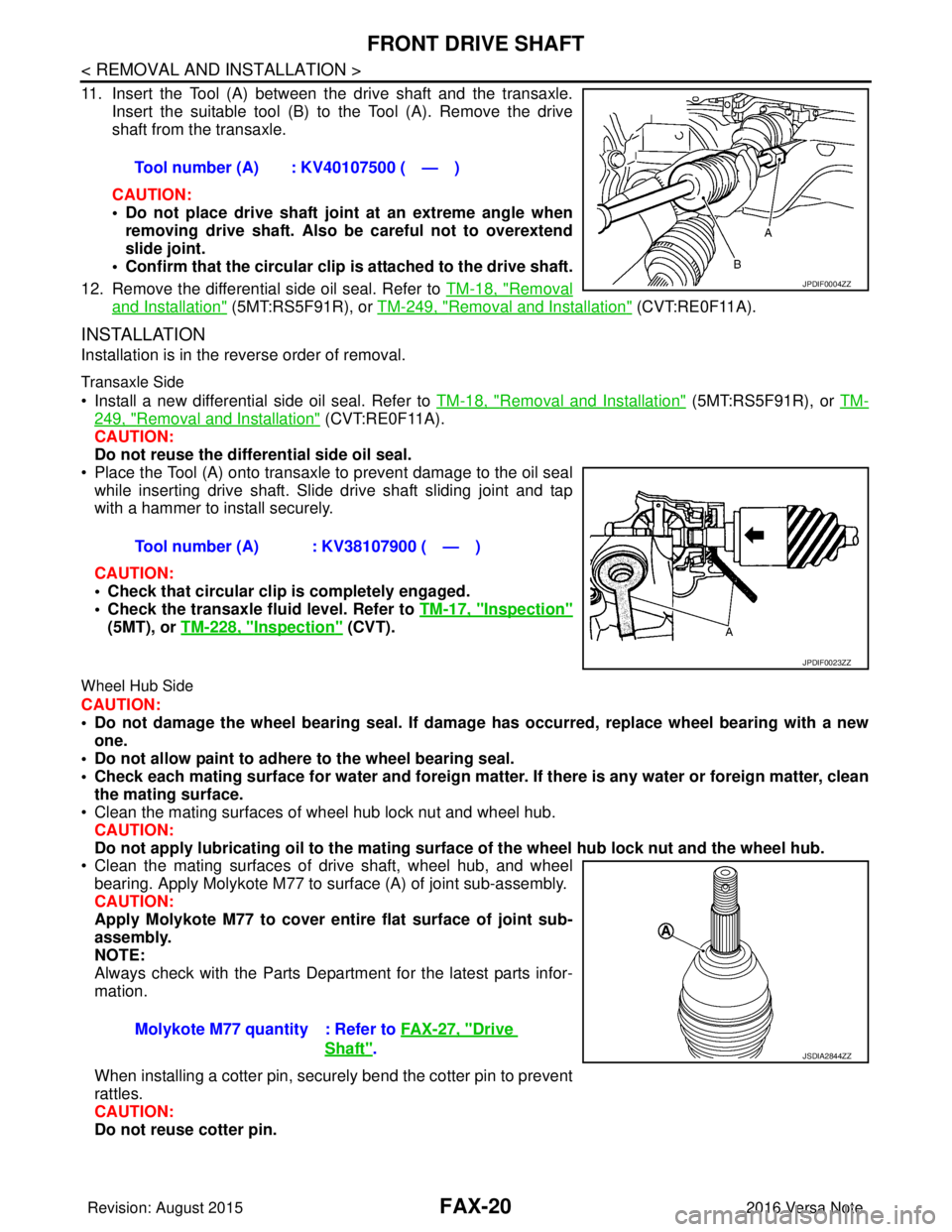
11. Insert the Tool (A) between the drive shaft and the transaxle.
Insert the suitable tool (B) to the Tool (A). Remove the drive
shaft from the transaxle.
CAUTION:
• Do not place drive shaft joint at an extreme angle when removing drive shaft. Also be careful not to overextend
slide joint.
• Confirm that the circular clip is attached to the drive shaft.
12. Remove the differential side oil seal. Refer to TM-18, "
Removal
and Installation" (5MT:RS5F91R), or TM-249, "Removal and Installation" (CVT:RE0F11A).
INSTALLATION
Installation is in the reverse order of removal.
Transaxle Side
• Install a new differential side oil seal. Refer to TM-18, "Removal and Installation" (5MT:RS5F91R), or TM-
249, "Removal and Installation" (CVT:RE0F11A).
CAUTION:
Do not reuse the differential side oil seal.
• Place the Tool (A) onto transaxle to prevent damage to the oil seal while inserting drive shaft. Slide drive shaft sliding joint and tap
with a hammer to install securely.
CAUTION:
• Check that circular clip is completely engaged.
• Check the transaxle fluid level. Refer to TM-17, "
Inspection"
(5MT), or TM-228, "Inspection" (CVT).
Wheel Hub Side
CAUTION:
• Do not damage the wheel bearing seal. If damage has occurred, replace wheel bearing with a new
one.
• Do not allow paint to adhere to the wheel bearing seal.
• Check each mating surface for water and foreign matter. If there is any water or foreign matter, clean
the mating surface.
• Clean the mating surfaces of wheel hub lock nut and wheel hub.
CAUTION:
Do not apply lubricatin g oil to the mating surface of the wh eel hub lock nut and the wheel hub.
• Clean the mating surfaces of drive shaft, wheel hub, and wheel
bearing. Apply Molykote M77 to surface (A) of joint sub-assembly.
CAUTION:
Apply Molykote M77 to cover entire flat surface of joint sub-
assembly.
NOTE:
Always check with the Parts Department for the latest parts infor-
mation.
When installing a cotter pin, securely bend the cotter pin to prevent
rattles.
CAUTION:
Do not reuse cotter pin. Tool number (A) : KV40107500 ( — )
JPDIF0004ZZ
Tool number (A) : KV38107900 ( — )
JPDIF0023ZZ
Molykote M77 quantity : Refer to
FAX-27, "Drive
Shaft".JSDIA2844ZZ
Revision: August 2015 2016 Versa Note
cardiagn.com
Page 1839 of 3641
FAX-22
< UNIT DISASSEMBLY AND ASSEMBLY >
FRONT DRIVE SHAFT
Disassembly and Assembly
INFOID:0000000012431901
DISASSEMBLY (WHEEL SIDE)
1. Mount the drive shaft in a vise. CAUTION:
When mounting the drive shaft in a vise, always use aluminum or copper plates between the vise
and the drive shaft.
2. Remove the boot bands and slide the boot back.
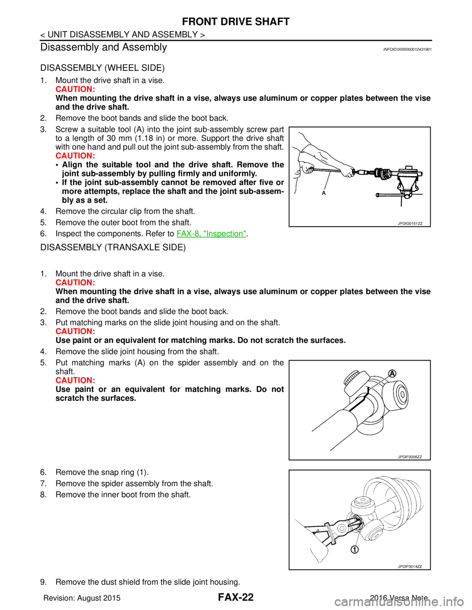
3. Screw a suitable tool (A) into the joint sub-assembly screw part to a length of 30 mm (1.18 in) or more. Support the drive shaft
with one hand and pull out the joint sub-assembly from the shaft.
CAUTION:
• Align the suitable tool and the drive shaft. Remove thejoint sub-assembly by pulli ng firmly and uniformly.
• If the joint sub-assembly cannot be removed after five or more attempts, replace the shaft and the joint sub-assem-
bly as a set.
4. Remove the circular clip from the shaft.
5. Remove the outer boot from the shaft.
6. Inspect the components. Refer to FAX-8, "
Inspection".
DISASSEMBLY (TRANSAXLE SIDE)
1. Mount the drive shaft in a vise. CAUTION:
When mounting the drive shaft in a vise, always use aluminum or copper plates between the vise
and the drive shaft.
2. Remove the boot bands and slide the boot back.
3. Put matching marks on the slide joint housing and on the shaft. CAUTION:
Use paint or an equivalent for matchi ng marks. Do not scratch the surfaces.
4. Remove the slide joint housing from the shaft.
5. Put matching marks (A) on the spider assembly and on the shaft.
CAUTION:
Use paint or an equivalent fo r matching marks. Do not
scratch the surfaces.
6. Remove the snap ring (1).
7. Remove the spider assembly from the shaft.
8. Remove the inner boot from the shaft.
9. Remove the dust shield from the slide joint housing.
JPDIG0151ZZ
JPDIF0006ZZ
JPDIF0014ZZ
Revision: August 2015 2016 Versa Note
cardiagn.com
Page 1841 of 3641
FAX-24
< UNIT DISASSEMBLY AND ASSEMBLY >
FRONT DRIVE SHAFT
Always check with the Parts Department for the latest parts information.
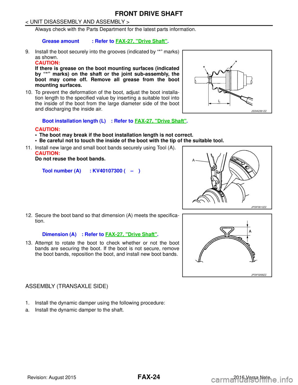
9. Install the boot securely into the grooves (indicated by “*” marks) as shown.
CAUTION:
If there is grease on the boot mounting surfaces (indicated
by “*” marks) on the shaft or the joint sub-assembly, the
boot may come off. Remove all grease from the boot
mounting surfaces.
10. To prevent the deformation of the boot, adjust the boot installa- tion length to the specified value by inserting a suitable tool into
the inside of the boot from the large diameter side of the boot
and discharging the inside air.
CAUTION:
• The boot may break if the boot installation length is not correct.
• Be careful not to touch the inside of the boot with the tip of the suitable tool.
11. Install new large and small boot bands securely using Tool (A). CAUTION:
Do not reuse the boot bands.
12. Secure the boot band so that dimension (A) meets the specifica- tion.
13. Attempt to rotate the boot to check whether or not the boot bands are securing the boot. If the boot is not secure, remove
the boot bands, reposition the boot, and install new boot bands.
ASSEMBLY (TRANSAXLE SIDE)
1. Install the dynamic damper using the following procedure:
a. Install the dynamic damper to the shaft. Grease amount : Refer to
FAX-27, "
Drive Shaft".
Boot installation length (L) : Refer to FAX-27, "
Drive Shaft".
Tool number (A) : KV40107300 ( – )
JSDIA2261ZZ
JPDIF0012ZZ
Dimension (A) : Refer to FAX-27, "Drive Shaft".
JPDIF0268ZZ
Revision: August 2015 2016 Versa Note
cardiagn.com