2016 NISSAN NOTE trans
[x] Cancel search: transPage 1891 of 3641
HOW TO USE THIS MANUALGI-3
< HOW TO USE THIS MANUAL >
C
DE
F
G H
I
J
K L
M B
GI
N
O PHOW TO USE THIS MANUAL
HOW TO USE THIS MANUAL
DescriptionINFOID:0000000012433142
This volume explains “Removal, Disassembly, Inst allation, Inspection and Adjustment” and “Trouble Diag-
noses”.
Te r m sINFOID:0000000012433143
• The captions WARNING and CAUTION warn you of steps that must be followed to prevent personal injury
and/or damage to some part of the vehicle.
WARNING indicates the possibility of personal injury if instructions are not followed.
CAUTION indicates the possibility of component damage if instructions are not followed.
BOLD TYPED STATEMENTS except WARNING and CAUTION give you helpful information.
Standard value: Tolerance at inspection and adjustment.
Limit value: The maximum or minimum limit val ue that should not be exceeded at inspection and adjust-
ment.
UnitsINFOID:0000000012433144
• The UNITS given in this manual are primarily expressed as the SI UNIT (International System of Unit), and
alternatively expressed in the metric system and in the yard/pound system.
Also with regard to tightening torque of bolts and nuts, there are descriptions both about range and about the
standard tightening torque.
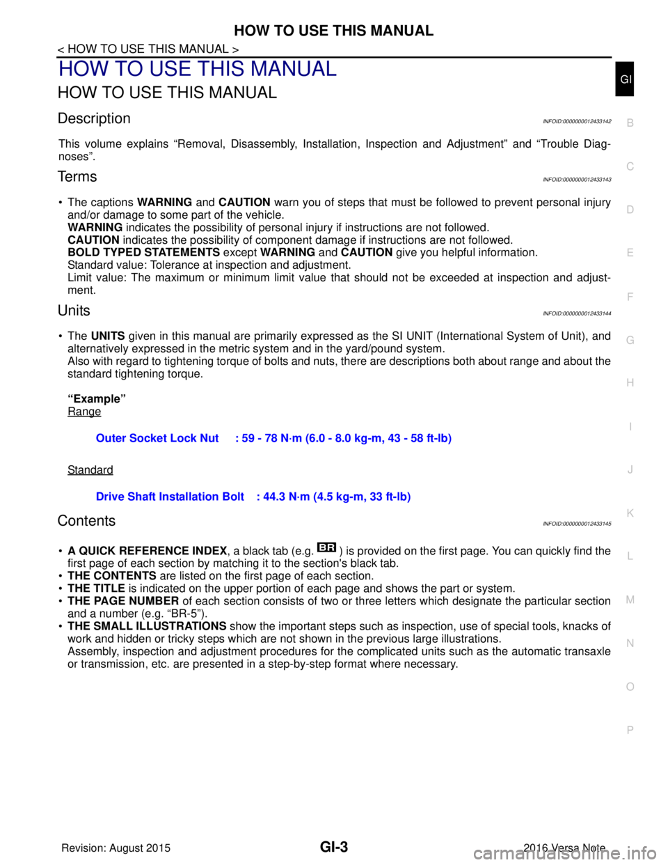
“Example”
Range
Standard
ContentsINFOID:0000000012433145
• A QUICK REFERENCE INDEX , a black tab (e.g. ) is provided on the first page. You can quickly find the
first page of each section by matching it to the section's black tab.
• THE CONTENTS are listed on the first page of each section.
• THE TITLE is indicated on the upper portion of each page and shows the part or system.
• THE PAGE NUMBER of each section consists of two or three letters which designate the particular section
and a number (e.g. “BR-5”).
• THE SMALL ILLUSTRATIONS show the important steps such as ins pection, use of special tools, knacks of
work and hidden or tricky steps which are not shown in the previous large illustrations.
Assembly, inspection and adjustment procedures for the complicated units such as the automatic transaxle
or transmission, etc. are presented in a step-by-step format where necessary. Outer Socket Lock Nut : 59 - 78 N·m (6.0 - 8.0 kg-m, 43 - 58 ft-lb)
Drive Shaft Installation Bolt : 44.3 N·m (4.5 kg-m, 33 ft-lb)
Revision: August 2015
2016 Versa Note
cardiagn.com
Page 1899 of 3641
HOW TO READ WIRING DIAGRAMSGI-11
< HOW TO USE THIS MANUAL >
C
DE
F
G H
I
J
K L
M B
GI
N
O P
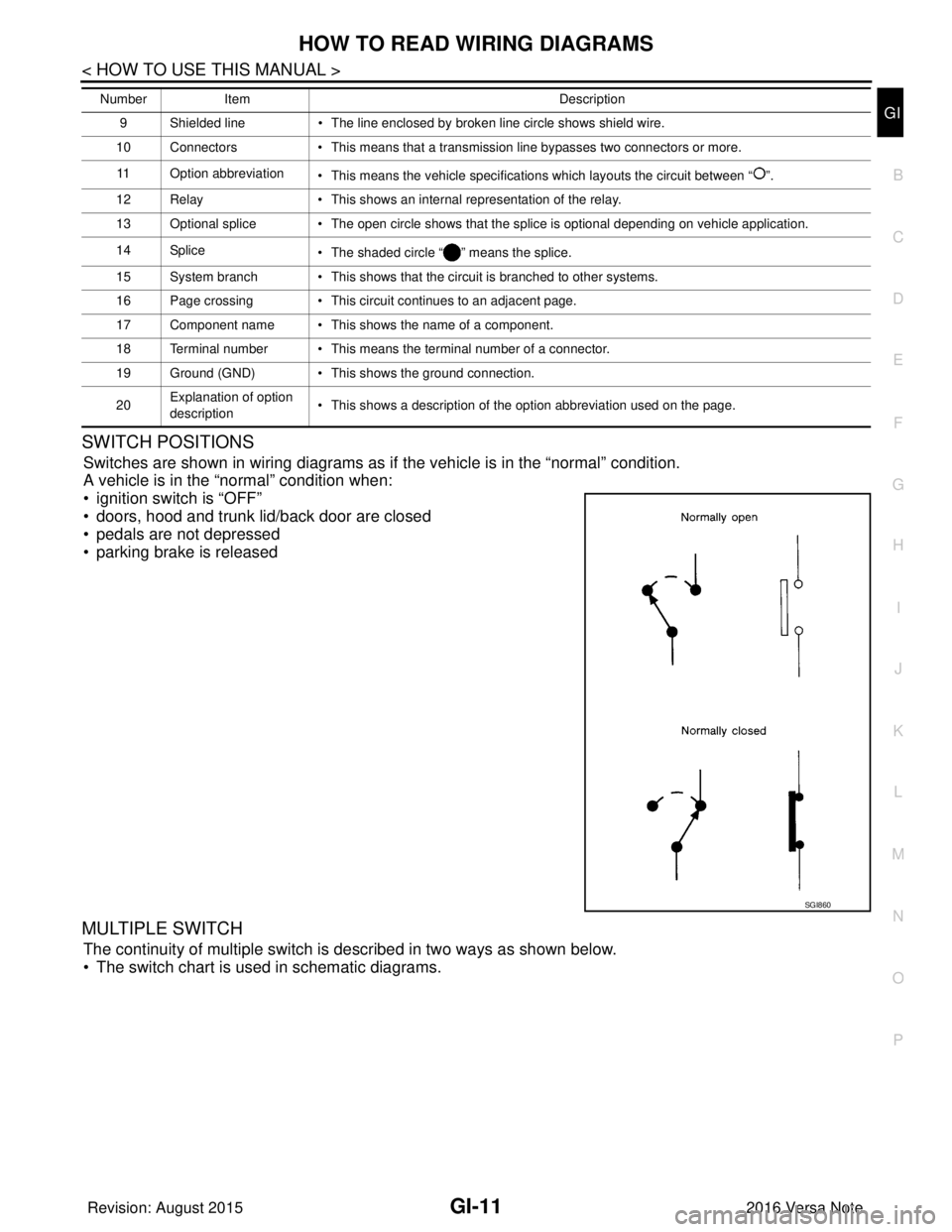
SWITCH POSITIONS
Switches are shown in wiring diagrams as if the vehicle is in the “normal” condition.
A vehicle is in the “normal” condition when:
• ignition switch is “OFF”
• doors, hood and trunk lid/back door are closed
• pedals are not depressed
• parking brake is released
MULTIPLE SWITCH
The continuity of multiple switch is described in two ways as shown below.
• The switch chart is used in schematic diagrams.
9 Shielded line • The line enclosed by broken line circle shows shield wire.
10 Connectors • This means that a transmission line bypasses two connectors or more.
11 Option abbreviation • This means the vehicle specifications which layouts the circuit between “ ”.
12 Relay • This shows an internal representation of the relay.
13 Optional splice • The open circle shows that the splice is optional depending on vehicle application.
14 Splice • The shaded circle “ ” means the splice.
15 System branch • This shows that the circuit is branched to other systems.
16 Page crossing • This circuit continues to an adjacent page.
17 Component name • This shows the name of a component.
18 Terminal number • This means the terminal number of a connector.
19 Ground (GND) • This shows the ground connection.
20 Explanation of option
description • This shows a description of the option abbreviation used on the page.
Number
Item Description
SGI860
Revision: August 2015 2016 Versa Note
cardiagn.com
Page 1902 of 3641

GI-14
< HOW TO USE THIS MANUAL >
ABBREVIATIONS
ABBREVIATIONS
Abbreviation ListINFOID:0000000012433154
The following ABBREVIATIONS are used:
A
B
C
D
ABBREVIATION DESCRIPTION
A/C Air conditioner
A/C Air conditioning
A/F sensor Air fuel ratio sensor A/T Automatic transaxle/transmission
ABS Anti-lock braking system
ACCS Advance climate control system ACL Air cleaner
AP Accelerator pedal
APP Accelerator pedal position
ATF Automatic transmission fluid
AV Audio visual
AVM Around view monitor
AWD All wheel drive
ABBREVIATION DESCRIPTION
BARO Barometric pressure BCI Backup collision intervention
BCM Body control module
BLSD Brake limited slip differential
BPP Brake pedal position
BSI Blind spot intervention
BSW Blind spot warning
ABBREVIATION DESCRIPTION
CKP Crankshaft position
CL Closed loop
CMP Camshaft position
CPP Clutch pedal position
CTP Closed throttle position
CVT Continuously variable transaxle/transmission
ABBREVIATION DESCRIPTION
D
1Drive range first gear
D
2Drive range second gear
D
3Drive range third gear
D
4Drive range fourth gear
DCA Distance control assist
DDS Downhill drive support
DFI Direct fuel injection system
Revision: August 2015 2016 Versa Note
cardiagn.com
Page 1904 of 3641

GI-16
< HOW TO USE THIS MANUAL >
ABBREVIATIONS
I
K
L
M
N
HOCHeated oxidation catalyst
HPCM Hybrid power train control module
ABBREVIATION DESCRIPTION
I/M Inspection and maintenance
IA Intake air
IAC Idle air control
IAT Intake air temperature
IBA Intelligent brake assist
IC Ignition control
ICC Intelligent cruise control
ICM Ignition control module
IPDM E/R Intelligent power distribution module engine room ISC Idle speed control
ISS Input shaft speed
ITS Information technology suite
ABBREVIATION DESCRIPTION
KS Knock sensor
ABBREVIATION DESCRIPTION
LBC Li-ion battery controller
LCD Liquid crystal display
LCU Local control unit
LDP Lane departure prevention
LDW Lane departure warning
LED Light emitting diode
LH Left-hand
LHD Left-hand drive
LIN Local interconnect network
ABBREVIATION DESCRIPTION
M/T Manual transaxle/transmission
MAF Mass airflow
MAP Manifold absolute pressure
MDU Multi display unit
MI Malfunction indicator
MIL Malfunction indicator lamp
MOD Moving object detection
ABBREVIATION DESCRIPTION
NOX Nitrogen oxides
ABBREVIATION
DESCRIPTION
Revision: August 2015 2016 Versa Note
cardiagn.com
Page 1905 of 3641

ABBREVIATIONSGI-17
< HOW TO USE THIS MANUAL >
C
DE
F
G H
I
J
K L
M B
GI
N
O P
O
P
R
S
T
ABBREVIATION DESCRIPTION
O2 Oxygen
O2S Oxygen sensor
OBD On board diagnostic
OC Oxidation catalytic converter
OD Overdrive
OL Open loop
OSS Output shaft speed
ABBREVIATION DESCRIPTION
P/S Power steering
PBR Potentio balance resistor
PCV Positive crankcase ventilation
PNP Park/Neutral position
PSP Power steering pressure
PTC Positive temperature coefficient
PTO Power takeoff
PWM Pulse width modulation
ABBREVIATION DESCRIPTION
RAM Random access memory
RAS Rear active steer
RH Right-hand
RHD Right-hand drive
ROM Read only memory
RPM Engine speed
RR Rear
ABBREVIATION DESCRIPTION
SAE Society of Automoti ve Engineers, Inc.
SCK Serial clock
SDS Service Data and Specifications
SRT System readiness test
SST Special Service Tools
ABBREVIATION DESCRIPTION
TC Turbocharger
TCM Transmission control module
TCS Traction control system
TCU Telematics communication unit
TP Throttle position
TPMS Tire pressure monitoring system TSS Turbine shaft speed
TWC Three way catalytic converter
Revision: August 2015 2016 Versa Note
cardiagn.com
Page 1912 of 3641
GI-24
< PRECAUTION >
PRECAUTIONS
General Precautions
INFOID:0000000012433162
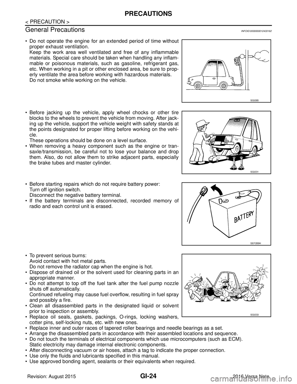
• Do not operate the engine for an extended period of time without proper exhaust ventilation.
Keep the work area well ventilated and free of any inflammable
materials. Special care should be taken when handling any inflam-
mable or poisonous materials, such as gasoline, refrigerant gas,
etc. When working in a pit or other enclosed area, be sure to prop-
erly ventilate the area before working with hazardous materials.
Do not smoke while working on the vehicle.
• Before jacking up the vehicle, apply wheel chocks or other tire blocks to the wheels to prevent the vehicle from moving. After jack-
ing up the vehicle, support the vehicle weight with safety stands at
the points designated for proper lifting before working on the vehi-
cle.
These operations should be done on a level surface.
• When removing a heavy component such as the engine or tran- saxle/transmission, be careful not to lose your balance and drop
them. Also, do not allow them to strike adjacent parts, especially
the brake tubes and master cylinder.
• Before starting repairs which do not require battery power: Turn off ignition switch.
Disconnect the negative battery terminal.
• If the battery terminals are disconnected, recorded memory of radio and each control unit is erased.
• To prevent serious burns: Avoid contact with hot metal parts.
Do not remove the radiator cap when the engine is hot.
• Dispose of drained oil or the solvent used for cleaning parts in an appropriate manner.
• Do not attempt to top off the fuel tank after the fuel pump nozzle
shuts off automatically.
Continued refueling may cause fuel overflow, resulting in fuel spray
and possibly a fire.
• Clean all disassembled parts in the designated liquid or solvent prior to inspection or assembly.
• Replace oil seals, gaskets, packings, O-rings, locking washers,
cotter pins, self-locking nuts, etc. with new ones.
• Replace inner and outer races of tapered roller bearings and needle bearings as a set.
• Arrange the disassembled parts in accordance with their assembled locations and sequence.
• Do not touch the terminals of electrical com ponents which use microcomputers (such as ECM).
Static electricity may damage internal electronic components.
• After disconnecting vacuum or air hoses, atta ch a tag to indicate the proper connection.
• Use only the fluids and lubricants specified in this manual.
• Use approved bonding agent, sealants or their equivalents when required.
SGI285
SGI231
SEF289H
SGI233
Revision: August 2015 2016 Versa Note
cardiagn.com
Page 1913 of 3641
PRECAUTIONSGI-25
< PRECAUTION >
C
DE
F
G H
I
J
K L
M B
GI
N
O P
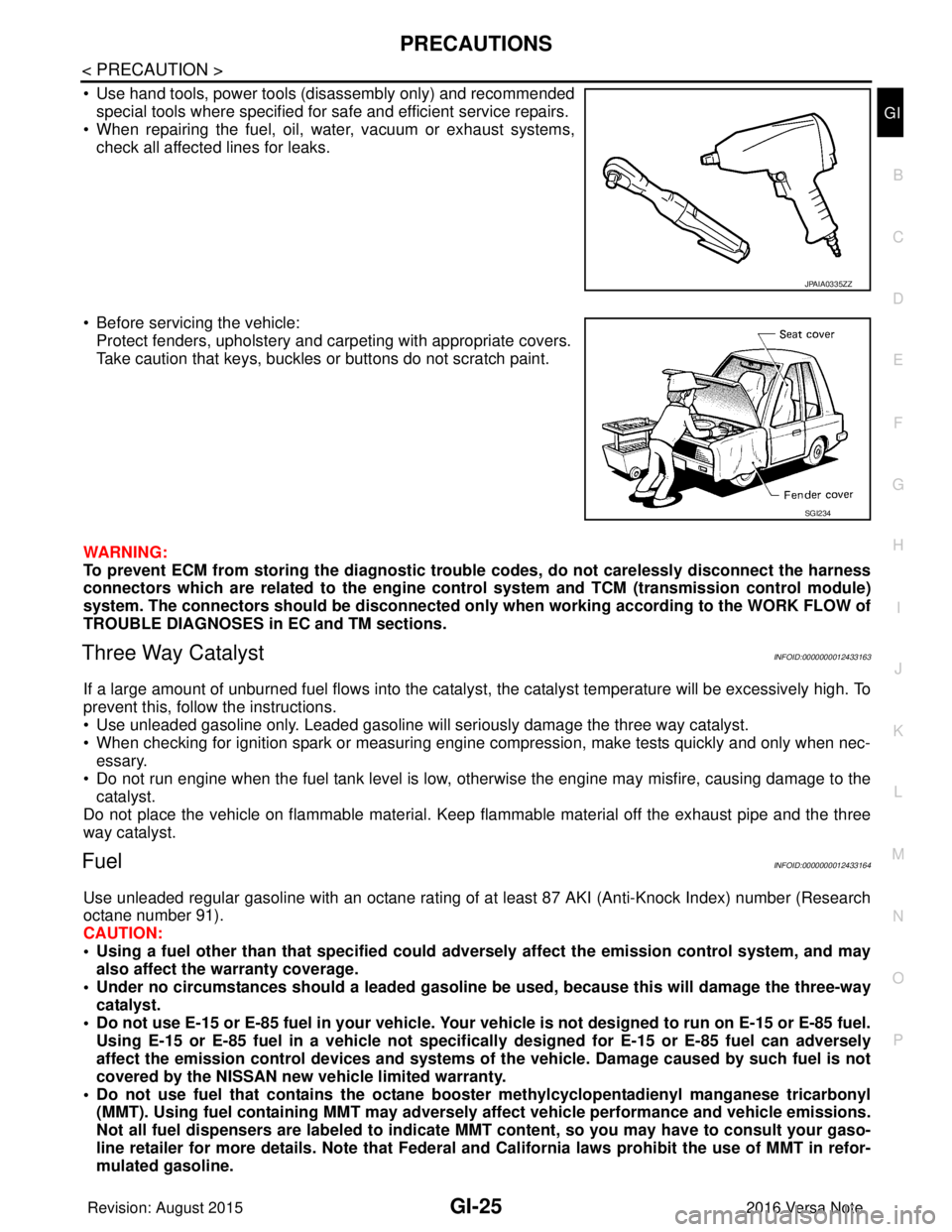
• Use hand tools, power tools (disassembly only) and recommended special tools where specified for safe and efficient service repairs.
• When repairing the fuel, oil, water, vacuum or exhaust systems,
check all affected lines for leaks.
• Before servicing the vehicle: Protect fenders, upholstery and carpeting with appropriate covers.
Take caution that keys, buckles or buttons do not scratch paint.
WARNING:
To prevent ECM from storing the diagnostic trou ble codes, do not carelessly disconnect the harness
connectors which are related to the engine cont rol system and TCM (transmission control module)
system. The connectors should be disconnected only when working according to the WORK FLOW of
TROUBLE DIAGNOSES in EC and TM sections.
Three Way CatalystINFOID:0000000012433163
If a large amount of unburned fuel flows into the catalyst, the catalyst temperature will be excessively high. To
prevent this, follow the instructions.
• Use unleaded gasoline only. Leaded gasoline will seriously damage the three way catalyst.
• When checking for ignition spark or measuring engine compression, make tests quickly and only when nec-
essary.
• Do not run engine when the fuel tank level is low, otherwise the engine may misfire, causing damage to the
catalyst.
Do not place the vehicle on flammable material. Keep flammable material off the exhaust pipe and the three
way catalyst.
FuelINFOID:0000000012433164
Use unleaded regular gasoline with an octane rating of at least 87 AKI (Anti-Knock Index) number (Research
octane number 91).
CAUTION:
• Using a fuel other than that specified could adversely affect th e emission control system, and may
also affect the warranty coverage.
• Under no circumstances should a leaded gasoline be used, because this will damage the three-way
catalyst.
• Do not use E-15 or E-85 fuel in your vehicle. Your vehicle is not designed to run on E-15 or E-85 fuel. Using E-15 or E-85 fuel in a vehicle not specifically designed for E-15 or E-85 fuel can adversely
affect the emission control devices and systems of the vehicle. Damage caused by such fuel is not
covered by the NISSAN new vehicle limited warranty.
• Do not use fuel that contains the octane boo ster methylcyclopentadienyl manganese tricarbonyl
(MMT). Using fuel containing MM T may adversely affect vehicle pe rformance and vehicle emissions.
Not all fuel dispensers are labeled to indicate MMT content, so you may have to consult your gaso-
line retailer for more details. Note that Federal and California laws prohibit the use of MMT in refor-
mulated gasoline.
JPAIA0335ZZ
SGI234
Revision: August 2015 2016 Versa Note
cardiagn.com
Page 1916 of 3641
GI-28
< PRECAUTION >
LIFTING POINT
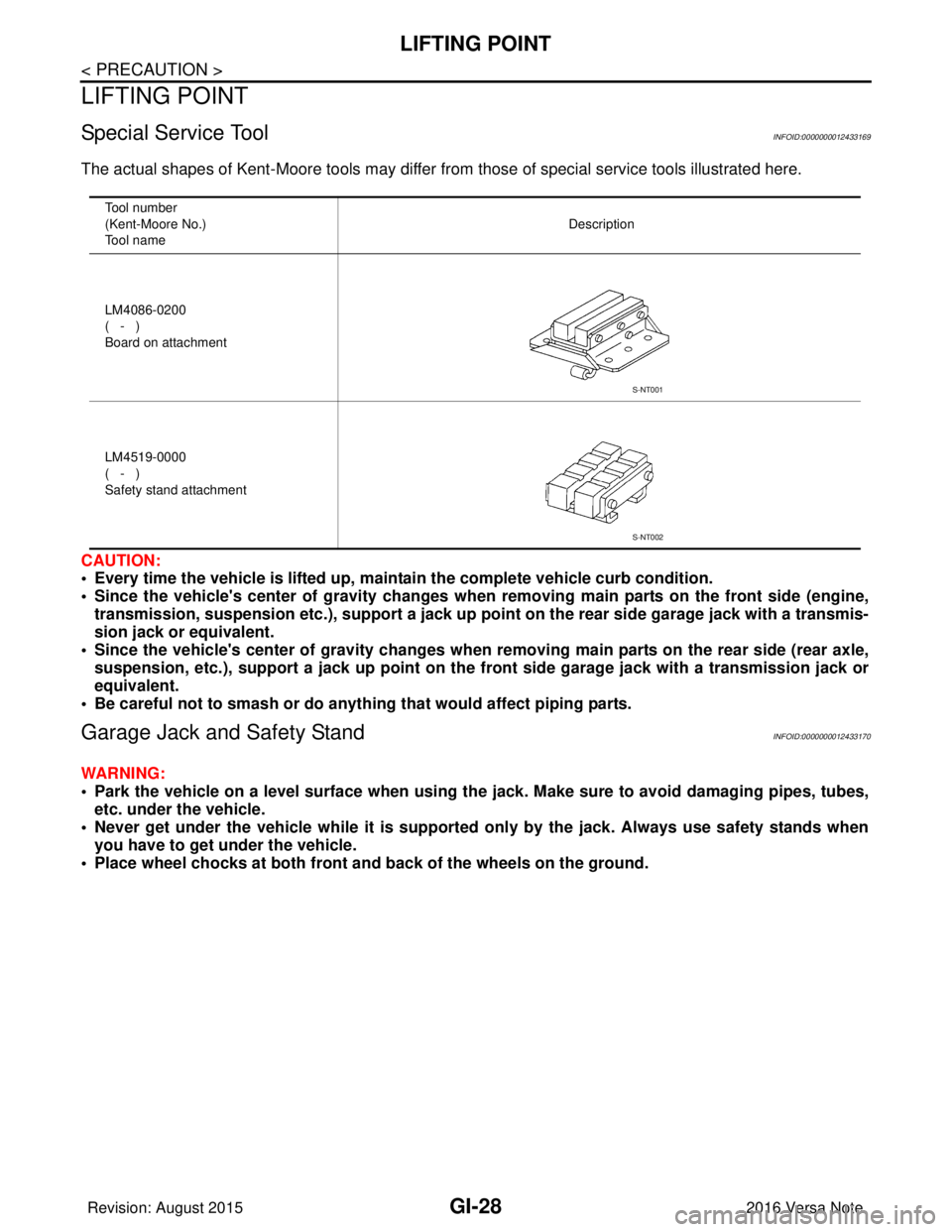
LIFTING POINT
Special Service ToolINFOID:0000000012433169
The actual shapes of Kent-Moore tools may differ from those of special service tools illustrated here.
CAUTION:
• Every time the vehicle is lifted up, main tain the complete vehicle curb condition.
• Since the vehicle's center of gravity changes when removing main parts on the front side (engine, transmission, suspension etc.), supp ort a jack up point on the rear side garage jack with a transmis-
sion jack or equivalent.
• Since the vehicle's center of gravity changes when removing main parts on the rear side (rear axle,
suspension, etc.), support a jack up point on the front side garage jack with a transmission jack or
equivalent.
• Be careful not to smash or do anything that would affect piping parts.
Garage Jack and Safety StandINFOID:0000000012433170
WARNING:
• Park the vehicle on a level surface when using the jack. Make sure to avoid damaging pipes, tubes,
etc. under the vehicle.
• Never get under the vehicle while it is supported only by the jack. Always use safety stands when
you have to get under the vehicle.
• Place wheel chocks at both front an d back of the wheels on the ground.
Tool number
(Kent-Moore No.)
Tool name Description
LM4086-0200
( - )
Board on attachment
LM4519-0000
( - )
Safety stand attachment
S-NT001
S-NT002
Revision: August 2015 2016 Versa Note
cardiagn.com