2016 NISSAN NOTE trans
[x] Cancel search: transPage 1644 of 3641
![NISSAN NOTE 2016 Service Repair Manual LU-14
< REMOVAL AND INSTALLATION >[HR16DE]
OIL COOLER
INSPECTION AFTER REMOVAL
Oil Cooler
Check oil cooler for cracks. Check oil cooler for clogging by blowing compressed air through engine coolant
in NISSAN NOTE 2016 Service Repair Manual LU-14
< REMOVAL AND INSTALLATION >[HR16DE]
OIL COOLER
INSPECTION AFTER REMOVAL
Oil Cooler
Check oil cooler for cracks. Check oil cooler for clogging by blowing compressed air through engine coolant
in](/manual-img/5/57363/w960_57363-1643.png)
LU-14
< REMOVAL AND INSTALLATION >[HR16DE]
OIL COOLER
INSPECTION AFTER REMOVAL
Oil Cooler
Check oil cooler for cracks. Check oil cooler for clogging by blowing compressed air through engine coolant
inlet. If necessary, replace oil cooler.
Relief Valve
Inspect relief valve for movement, cracks and breaks by
pushing the ball. If replacement is necessary, remove
the valve by prying it out using a suitable tool. Install a new valve by tapping it in place.
INSTALLATION
Installation is in the reverse order of removal.
• Ensure that no foreign objects are adhering to the s ealing surfaces of the oil cooler and oil pan (upper).
• Tighten connector bolt after aligning cutout (1) on oil cooler with protrusion (2) on oil pan (upper) side.
CAUTION:
• Do not reuse O-ring.
• Replace relief valve if removed.
INSPECTION AFTER INSTALLATION
• Before starting engine, check oil/fluid levels, including engine coolant and engine oil. If less than required
quantity, fill to the specified level. Refer to MA-11, "
Fluids and Lubricants".
• Use procedure below to check for fuel leaks.
• Turn ignition switch ON (with engine stopped). With fuel pressure applied to fuel piping, check for fuel leaks
at connection points.
• Start engine. With engine speed increased, che ck again for fuel leaks at connection points.
• Run engine to check for unusual noise and vibration. NOTE:
If hydraulic pressure inside timing chain tensioner drops after removal and installation, slack in the guide
may generate a pounding noise during and just after engine start. However, this is normal. Noise will stop
after hydraulic pressure rises.
• Warm up engine thoroughly to make sure there is no leak s of fuel, exhaust gas, or any oils/fluids including
engine oil and engine coolant.
• Bleed air from passages in lines and hoses, such as in cooling system.
• After cooling down engine, again check oil/fluid levels, including engine oil and engine coolant. Refill to spec-
ified level, if necessary.
• Summary of the inspection items:
*Power steering fluid, brake fluid, etc.
AWBIA1139GB
Item Before starting engine Engine runningAfter engine stopped
Engine coolant LevelLeaks Level
Engine oil LevelLeaks Level
Transmission/
transaxle fluid CVT Models
LeaksLevel/Leaks Leaks
M/T Models Level/Leaks LeaksLevel/Leaks
Other oils and fluids* LevelLeaks Level
Fuel LeaksLeaksLeaks
Exhaust gas —Leaks —
Revision: August 2015 2016 Versa Note
cardiagn.com
Page 1662 of 3641

EXL-10
< SYSTEM DESCRIPTION >
SYSTEM
FRONT FOG LAMP SYSTEM : System Description
INFOID:0000000012432774
FRONT FOG LAMP OPERATION
When the combination switch (lighting and turn signal switch) is in front fog lamp ON position and also in 1ST
or 2ND position (headlamp is ON), the BCM detects FR FOG ON and the HEAD LAMP 1 or 2 ON. The BCM
sends a front fog lamp request ON signal through the CAN communication lines to the IPDM E/R. The IPDM
E/R then turns ON the front fog lamp relay sending power to the front fog lamps.
TURN SIGNAL AND HAZARD WARNING LAMP SYSTEM
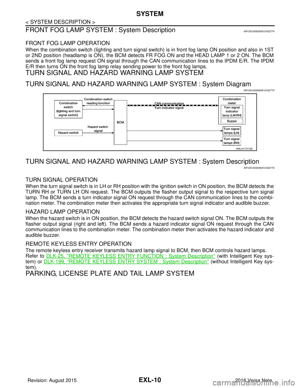
TURN SIGNAL AND HAZARD WARNING LAMP SYSTEM : System Diagram
INFOID:0000000012432775
TURN SIGNAL AND HAZARD WARNING LA MP SYSTEM : System Description
INFOID:0000000012432776
TURN SIGNAL OPERATION
When the turn signal switch is in LH or RH position with the ignition switch in ON position, the BCM detects the
TURN RH or TURN LH ON request. The BCM outputs the flasher output signal to the respective turn signal
lamp. The BCM sends a turn indicator signal ON request through the CAN communication lines to the combi-
nation meter. The combination meter then activates the appropriate turn signal indicator and audible buzzer.
HAZARD LAMP OPERATION
When the hazard switch is in ON position, the BCM det ects the hazard switch signal ON. The BCM outputs the
flasher output signal (right and left). The BCM sends a hazard indicator signal ON request through the CAN
communication lines to the combination meter. The combination meter then activates the hazard indicator and
audible buzzer.
REMOTE KEYLESS ENTRY OPERATION
The remote keyless entry receiver transmits hazard lamp signal to BCM, then BCM controls hazard lamps.
Refer to DLK-25, "
REMOTE KEYLESS ENTRY FUNCTION : System Description" (with Intelligent Key sys-
tem) or DLK-199, "
REMOTE KEYLESS ENTRY SYSTEM : System Description" (without Intelligent Key sys-
tem).
PARKING, LICENSE PLATE AND TAIL LAMP SYSTEM
AWLIA1721GB
Revision: August 2015 2016 Versa Note
cardiagn.com
Page 1664 of 3641

EXL-12
< SYSTEM DESCRIPTION >
DIAGNOSIS SYSTEM (BCM) (WITH INTELLIGENT KEY SYSTEM)
DIAGNOSIS SYSTEM (BCM) (WITH INTELLIGENT KEY SYSTEM)
COMMON ITEM
COMMON ITEM : CONSULT Function (BCM - COMMON ITEM)INFOID:0000000012542302
APPLICATION ITEM
CONSULT performs the following functions via CAN communication with BCM.
SYSTEM APPLICATION
BCM can perform the following functions.
Direct Diagnostic Mode Description
ECU Identification The BCM part number is displayed.
Self Diagnostic Result The BCM self diagnostic results are displayed.
Data Monitor The BCM input/output data is displayed in real time.
Active Test The BCM activates outputs to test components.
Work support The settings for BCM functions can be changed.
Configuration • The vehicle specification can be read and saved.
• The vehicle specification can be written when replacing BCM.
CAN DIAG SUPPORT MNTR The result of transmit/receive diagnosis of CAN communication is displayed.
System Sub System Direct Diagnostic Mode
ECU Identification
Self Diagnostic Result
Data Monitor
Active Test
Work support
Configuration
CAN DIAG SUPPORT MNTR
Door lock
DOOR LOCK ×××
Rear window defogger REAR DEFOGGER ××
Warning chime BUZZER ××
Interior room lamp timer INT LAMP ×××
Exterior lamp HEAD LAMP ×××
Wiper and washer WIPER ×××
Turn signal and hazard warning lamps FLASHER ×××
Air conditioner AIR CONDITIONER ×
Intelligent Key system INTELLIGENT KEY ××××
Combination switch COMB SW ×
BCM BCM× × ×××
Immobilizer IMMU ××××
Interior room lamp battery saver BATTERY SAVER ×××
Vehicle security system THEFT ALM ××
RAP system RETAINED PWR ×
Signal buffer system SIGNAL BUFFER ×
TPMS AIR PRESSURE MONITOR ××××
Panic alarm system PANIC ALARM ×
Revision: August 2015 2016 Versa Note
cardiagn.com
Page 1668 of 3641

EXL-16
< SYSTEM DESCRIPTION >
DIAGNOSIS SYSTEM (BCM) (WITHOUT INTELLIGENT KEY SYSTEM)
DIAGNOSIS SYSTEM (BCM) (WITHOUT INTELLIGENT KEY SYSTEM)
COMMON ITEM
COMMON ITEM : CONSULT Function (BCM - COMMON ITEM)INFOID:0000000012542311
APPLICATION ITEM
CONSULT performs the following functions via CAN communication with BCM.
SYSTEM APPLICATION
BCM can perform the following functions.
Direct Diagnostic Mode Description
ECU Identification The BCM part number is displayed.
Self Diagnostic Result The BCM self diagnostic results are displayed.
Data Monitor The BCM input/output data is displayed in real time.
Active Test The BCM activates outputs to test components.
Work support The settings for BCM functions can be changed.
Configuration • The vehicle specification can be read and saved.
• The vehicle specification can be written when replacing BCM.
CAN DIAG SUPPORT MNTR The result of transmit/receive diagnosis of CAN communication is displayed.
System Sub System Direct Diagnostic Mode
ECU Identification
Self Diagnostic Result
Data Monitor
Active Test
Work support
Configuration
CAN DIAG SUPPORT MNTR
Door lock
DOOR LOCK ×××
Rear window defogger REAR DEFOGGER ××
Warning chime BUZZER ××
Interior room lamp timer INT LAMP ×××
Remote keyless entry system MULTI REMOTE ENT ×××
Exterior lamp HEAD LAMP ×××
Wiper and washer WIPER ×××
Turn signal and hazard warning lamps FLASHER ××
Air conditioner AIR CONDITIONER ×
Combination switch COMB SW ×
BCM BCM× × ×××
Immobilizer IMMU ×××
Interior room lamp battery saver BATTERY SAVER ×××
Vehicle security system THEFT ALM ××
RAP system RETAINED PWR ××
Signal buffer system SIGNAL BUFFER ×
TPMS AIR PRESSURE MONITOR ××××
Panic alarm system PANIC ALARM ×
Revision: August 2015 2016 Versa Note
cardiagn.com
Page 1673 of 3641

DIAGNOSIS SYSTEM (IPDM E/R)EXL-21
< SYSTEM DESCRIPTION >
C
DE
F
G H
I
J
K
M A
B
EXL
N
O P
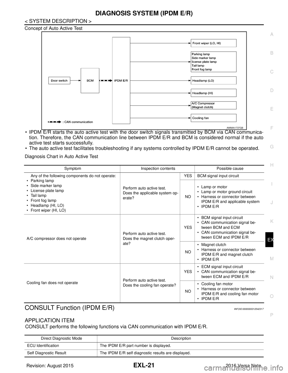
Concept of Auto Active Test
• IPDM E/R starts the auto active test with the door
switch signals transmitted by BCM via CAN communica-
tion. Therefore, the CAN communication line between IPDM E/R and BCM is considered normal if the auto
active test starts successfully.
• The auto active test facilitates troubleshooting if any systems controlled by IPDM E/R cannot be operated.
Diagnosis Chart in Auto Active Test
CONSULT Function (IPDM E/R)INFOID:0000000012542317
APPLICATION ITEM
CONSULT performs the following functions via CAN communication with IPDM E/R.
AWMIA1737GB
SymptomInspection contentsPossible cause
Any of the following components do not operate:
•Parking lamp
• Side marker lamp
• License plate lamp
•Tail lamp
•Front fog lamp
• Headlamp (HI, LO)
• Front wiper (HI, LO) Perform auto active test.
Does the applicable system op-
erate?YES BCM signal input circuit
NO • Lamp or motor
• Lamp or motor ground circuit
• Harness or connector between
IPDM E/R and applicable system
•IPDM E/R
A/C compressor does not operate Perform auto active test.
Does the magnet clutch oper-
ate?YES
• BCM signal input circuit
• CAN communication signal be-
tween BCM and ECM
• CAN communication signal be-
tween ECM and IPDM E/R
NO • Magnet clutch
• Harness or connector between
IPDM E/R and magnet clutch
•IPDM E/R
Cooling fan does not operate Perform auto active test.
Does the cooling fan operate?YES
• ECM signal input circuit
• CAN communication signal be-
tween ECM and IPDM E/R
NO • Cooling fan motor
• Harness or connector between
IPDM E/R and cooling fan motor
•IPDM E/R
Direct Diagnostic Mode Description
ECU Identification The IPDM E/R part number is displayed.
Self Diagnostic Result The IPDM E/R self diagnostic results are displayed.
Revision: August 2015 2016 Versa Note
cardiagn.com
Page 1674 of 3641

EXL-22
< SYSTEM DESCRIPTION >
DIAGNOSIS SYSTEM (IPDM E/R)
ECU IDENTIFICATION
The IPDM E/R part number is displayed.
SELF DIAGNOSTIC RESULT
Refer to PCS-20, "DTCIndex".
DATA MONITOR
ACTIVE TEST
Data Monitor The IPDM E/R input/output data is displayed in real time.
Active Test The IPDM E/R activates outputs to test components.
CAN Diag Support Mntr The result of transmit/receive diagnosis of CAN communication is displayed.
Direct Diagnostic Mode
Description
Monitor Item [Unit]Main
Signals Description
MOTOR FAN REQ [1/2/3/4] ×Indicates cooling fan speed signal received from ECM on CAN communication
line
AC COMP REQ [On/Off] ×Indicates A/C compressor request signal received from ECM on CAN commu-
nication line
TAIL&CLR REQ [On/Off] ×Indicates position light request signal received from BCM on CAN communica-
tion line
HL LO REQ [On/Off] ×Indicates low beam request signal received from BCM on CAN communication
line
HL HI REQ [On/Off] ×Indicates high beam request signal received from BCM on CAN communication
line
FR FOG REQ [On/Off] ×Indicates front fog light request signal received from BCM on CAN communica-
tion line
FR WIP REQ [Stop/1LOW/Low/Hi] ×Indicates front wiper request signal received from BCM on CAN communication
line
WIP AUTO STOP [STOP P/ACT P] ×Indicates condition of front wiper auto stop signal
WIP PROT [Off/BLOCK] ×Indicates condition of front wiper fail-safe operation
IGN RLY1 -REQ [On/Off] Indicates ignition switch ON signal received from BCM on CAN communication
line
IGN RLY [On/Off] ×Indicates condition of ignition relay
PUSH SW [On/Off] Indicates condition of push-button ignition switch
INTER/NP SW [On/Off] Indicates condition of CVT shift position
ST RLY CONT [On/Off] Indicates starter relay status signal received from BCM on CAN communication
line
IHBT RLY -REQ [On/Off] Indicates starter control relay signal received from BCM on CAN communication
line
ST/INHI RLY [Off/ ST /INHI] Indicates condition of starter relay and starter control relay
DETENT SW [On/Off] Indicates condition of CVT shift selector (park position switch)
DTRL REQ [Off] Indicates daytime running light request signal received from BCM on CAN com-
munication line
THFT HRN REQ [On/Off] Indicates theft warning horn request signal received from BCM on CAN commu-
nication line
HORN CHIRP [On/Off] Indicates horn reminder signal received from BCM on CAN communication line
Te s t i t e m D e s c r i p t i o n
HORN This test is able to check horn operation [On].
FRONT WIPER This test is able to check wiper motor operation [Hi/Lo/Off].
Revision: August 2015 2016 Versa Note
cardiagn.com
Page 1778 of 3641

SYSTEMEXT-11
< SYSTEM DESCRIPTION >
C
DE
F
G H
I
J
L
M A
B
EXT
N
O P
SYSTEM
ACTIVE GRILLE SHUTTER SYSTEM
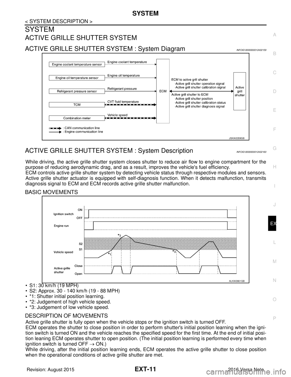
ACTIVE GRILLE SHUTTER SYSTEM : System DiagramINFOID:0000000012432159
ACTIVE GRILLE SHUTTER SYSTEM : System DescriptionINFOID:0000000012432160
While driving, the active grille shutter system closes shutter to reduce air flow to engine compartment for the
purpose of reducing aerodynamic drag, and as a resu lt, improves the vehicle's fuel efficiency.
ECM controls active grille shutter system by detecting vehicle status through respective modules and sensors.
Active grille shutter actuator is equipped with self-d iagnosis function. When it detects malfunction, transmits
diagnosis signal to ECM and ECM records active grille shutter malfunction.
BASIC MOVEMENTS
• S1: 30 km/h (19 MPH)
• S2: Approx. 30 - 140 km/h (19 - 88 MPH)
• *1: Shutter initial position learning.
• *2: Judgement of high vehicle speed.
• *3: Judgement of low vehicle speed.
DESCRIPTION OF MOVEMENTS
Active grille shutter is fully open when the vehicl e stops or the ignition switch is turned OFF.
ECM operates the shutter to close position in order to perform shutter's initial position learning when the igni-
tion switch is turned ON and the vehicle reaches the specified speed for the first time. At the end of initial posi-
tion leaning ECM operates shutter to open position. (The in itial position learning is performed every time when
ignition switch is turned OFF → ON.)
While driving, after the initial position learning ends, EC M operates the active grille shutter to close position
when the operational conditions of active grille shutter are met.
JSKIA3359GB
ALKIA3661GB
Revision: August 2015 2016 Versa Note
cardiagn.com
Page 1787 of 3641

EXT-20
< SYMPTOM DIAGNOSIS >
SQUEAK AND RATTLE TROUBLE DIAGNOSES
1. Loose harness or harness connectors.
2. Front console map/reading lamp lens loose.
3. Loose screws at console attachment points.
SEATS
When isolating seat noise it's important to note the position the seat is in and the load placed on the seat when
the noise is present. These conditions should be duplicated when verifying and isolating the cause of the
noise.
Cause of seat noise include:
1. Headrest rods and holder
2. A squeak between the seat pad cushion and frame
3. The rear seatback lock and bracket
These noises can be isolated by moving or pressing on the suspected components while duplicating the con-
ditions under which the noise occurs. Most of thes e incidents can be repaired by repositioning the component
or applying urethane tape to the contact area.
UNDERHOOD
Some interior noise may be caused by components under the hood or on the engine wall. The noise is then
transmitted into the passenger compartment.
Causes of transmitted underhood noise include:
1. Any component installed to the engine wall
2. Components that pass through the engine wall
3. Engine wall mounts and connectors
4. Loose radiator installation pins
5. Hood bumpers out of adjustment
6. Hood striker out of adjustment
These noises can be difficult to isolate since they cannot be reached from the interior of the vehicle. The best
method is to secure, move or insulate one component at a time and test drive the vehicle. Also, engine rpm or
load can be changed to isolate the noise. Repairs can usually be made by moving, adjusting, securing, or
insulating the component causing the noise.
Revision: August 2015 2016 Versa Note
cardiagn.com