Page 201 of 404

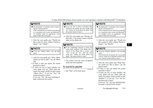
How to use the rear-view cam-era
When you place the shift lever in the “R” (Reverse) position (on vehicles with M/T) or
selector lever in the “R” (REVERSE) posi-
tion (on vehicles with A/T) with the ignition
switch in the “ON” position, the view behind
the vehicle will automatically appear on the screen of the MITSUBISHI Multi Communi-
cation System (MMCS), the DISPLAY AU- DIO or the Smartphone Link Display Audio.
When you move the shift lever or selector
lever to any other position, the screen will re- turn to its original indication.
CAUTIONl The rear-view camera has a special lens that
can make objects shown on the screen ap-
pear to be closer or further away than they
actually are.CAUTIONl The line (red) shows the point approximately
50 cm behind the rear extremity of the rear
bumper.
Be careful because the spare wheel garnish overhangs for approximately 30 cm behind
the rear extremity of the rear bumper.NOTEl Because the rear-view camera has a special
lens, the lines on the ground between park-
ing spaces may not look parallel on the screen.
l In the following situations, the screen indi-
cation may be difficult to see. There is no abnormality.
• Low light (night time)
• When the light of the sun or the light from
a vehicle’s headlamps shines directly into
the lens
l If the camera is hot and is then cooled by
rain or a car wash, the lens can mist up. This
phenomenon does not indicate a malfunc- tion.
l It is not possible to fully see obstacles when
the lens is dirty. If the lens becomes conta- minated by water droplets, snow, mud or oil,
wipe off the contamination, taking care not to scratch the lens.
l Please observe the following cautions. Ig-
noring them could lead to a camera malfunc-
tion.
• Do not subject the camera to physical
shock.NOTE• Do not apply wax to the camera.
• Do not splash the camera with boiling wa-
ter.
• Do not disassemble the camera.
Reference lines on the screen
Reference lines and upper surface of the rear
bumper (A) are displayed on the screen.
l Red line (B) indicates approximately
50 cm behind the rear bumper.
l Two Green lines (C) indicate approxi-
mately 20 cm outside of the vehicle body.
l Short transverse lines (1 to 3) indicate
distance from the rear bumper.
Check surroundings for safety.
1- Approximately at the rear edge of the rear bumper
2- Approximately 100 cm
3- Approximately 200 cm
Rear-view camera*
6-62OVWE16E1Starting and driving6
Page 202 of 404

NOTElWhen the vehicle is tilting because of the
number of people in the vehicle, the weight and positioning of luggage, and/or the condi-tion of the road surface, the lines in the view
from the rear-view camera may not be accu- rately positioned relative to the actual road.
l The reference lines for distance and vehicle
width are based on a level, flat road surface. In the following cases, objects shown on thescreen will appear to be farther off than they
actually are.
• When the rear of the vehicle is weighed
down with the weight of passengers and
luggage in the vehicle.
A- Actual objects
B- Objects shown on the screen
• When there is an upward slope at the
back.
NOTE
A- Actual objects
B- Objects shown on the screen
NOTEl The reference lines for distance and vehicle
width are intended to indicate the distance to
a flat object such as a level, flat road surface.
This may make the distance to a projecting object shown on the screen differ from the actual distance to the projecting object. Do
not use them as a guide for distances to solid objects.
Example: Example: On the screen the point B appears the nearest, then the point C and
A in order of distance. The points A and B actually are the same distances from the ve-
hicle, and the point C is farther off than the points A and B.
Rear-view camera*
6-63OVWE16E1Starting and driving6 Check surroundings for safety
Page 203 of 404

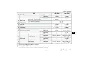
Cargo loadsE00609901224
Cargo loads precautionsCAUTIONl When loading luggage, be careful to the fol-
lowing.
• Stow cargo and luggage in the luggage
compartment whenever possible.
• Distribute cargo or luggage evenly not to
be unbalanced in weight.
• Do not place cargo or luggage on the in-
strument panel.
Also, do not stack up cargo or luggage on the front passenger’s seat or the rear seats.
Having the driver’s vision blocked, and your cargo being thrown inside the cabin
if you suddenly have to brake can cause a
serious accident or injury.
Loading a roof carrier
CAUTIONl Use a roof carrier that properly fits your ve-
hicle.
Do not load luggage directly onto the roof.
For installation, refer to the instruction man-
ual accompanying the roof carrier.Roof carrier mounting brack-
ets*3-door models5-door models
When installing the roof carrier, use the brackets (A). The brackets (A) are located
under each roof drip moulding (B).
NOTEl We recommend you to use a genuine
MITSUBISHI roof carrier, since the brack-
ets to be used have a special shape. For de-
tails, we recommend you to consult a
MITSUBISHI MOTORS Authorized Serv-
ice Point.Roof carrier precautionCAUTIONl Make sure that the weight of the luggage
does not exceed the allowable roof load.
If the allowable roof load is exceeded, this may cause damage to the vehicle.
The roof load is the total allowable load on
the roof (the weight of the roof carrier plus
the weight of luggage placed on the roof car- rier).
For specific figures, please refer to “Maxi-
mum roof load” on page 11-07 .
l When luggage is loaded onto the vehicle,
please make sure to drive slowly and avoid
excessive manoeuvres such as sudden brak- ing or quick turning.
In addition, place the luggage on the carrier
so that its weight is distributed evenly with the heaviest items on the bottom. Do not load items that are wider than the roof carri-
er.
The additional weight on the roof could raise
the vehicle’s centre of gravity and affect ve- hicle handling characteristics.
As a result, driving errors or emergency ma-
noeuvres could lead to a loss of control and
result in an accident.
l Before driving and after travelling a short
distance, always check the load to make sure it is securely fastened to the roof carrier.
Check periodically during your travel that
the load remains secure.
Cargo loads
6-64OVWE16E1Starting and driving6
Page 204 of 404

NOTElTo prevent wind noise or reduction in fuel
economy, remove the roof carrier when not
in use.
l Before using an automatic car wash, remove
the roof carrier.
l Be sure that adequate clearance is main-
tained for raising the sunroof (if so equip-
ped) when installing a roof carrier.Trailer towing
E00610000550
In order to tow a trailer with your vehicle,
when having a trailer towing device mounted that meets all relevant regulations in your
area, consult a MITSUBISHI MOTORS Au-
thorized Service Point.
The regulations concerning the towing of a
trailer may differ from country to country. You are advised to obey the regulations in
each area.
CAUTIONl Danger of Accident!
A towing bar should be fitted according to MITSUBISHI MOTORS guidelines.
When you are going to tow a trailer, move
the transfer shift lever to “4H” position.
Selecting the “2H” drive may increase the differential oil temperature, resulting in pos-sible damage to the driving system.
Further, the drive train will be subjected to
excessive loading possibly leading to oil leakage, component seizure, or other serious faults.
Maximum towable weight with
brake and maximum trailer- nose weight
Never exceed the maximum towable weight
with brake and the maximum trailer-nose weight as listed in the specifications. (Referto “Vehicle weight” on page 11-07 .)
If you tow a trailer at an altitude of more than
1,000 m above sea-level, reduce your weight
by 10 % of the gross combination weight for
every increase of 1,000 m above sea-level, as the engine output is lowered owing to de-
crease in atmospheric pressure.
Towing bar mounting specifi-
cations
See the following table for fixing points (A) for the towing bar.
Trailer towing
6-65OVWE16E1Starting and driving6
Page 205 of 404

3-door models5-door models1512.5 mm797 mm2564 mm564 mm38 mm8 mm4124 mm179 mm5131 mm131 mm644 mm44 mm755 mm55 mm8—149 mm9139 mm138 mm10473 mm491 mm11499.7 mm499.7 mm 3-door models5-door models12538 mm538 mm13—547 mm14576.3 mm576.3 mm
Item 8, 13: 5-door models only
Item 10: at kerb weight
NOTEl The values under item 10 are applicable to
unladen vehicles. These values can also be
varied depending on the tyre size, optional equipment and suspension conditions.
Operating hints
l Do not let the clutch slip (vehicles with
M/T only) and do not increase the en-
gine speed more than necessary when starting.
l Be sure that the driving speed does not
exceed 100 km/h (62 mph)* for trailer
operation. *: For vehicles with only front seats orvehicles with only front seats and sec-
ond seats (5-door models), 80 km/h
(50 mph) should be applied instead of 100 km/h (62 mph).
It is also recommended that you obey the
local regulations in case driving speed
with a trailer is limited to less than
100 km/h (62 mph).
l To prevent shocks from the overrun
brake, depress the brake pedal lightly at first and then more strongly.
l To make full use of engine braking,
change to a lower gear before descend-
ing a slope.
Additional precautions for vehi-
cles equipped with A/T
The 2nd
gear (in sports mode) is recommen-
ded on slopes or at low speed. Use the
1 st
gear (in sports mode) in mountainous
areas in order to make better use of engine braking and to assist the brake system. How-
ever, be sure that the speed does not exceed the maximum speed limit for the selected
gear.
Trailer towing
6-66OVWE16E1Starting and driving6
Page 206 of 404

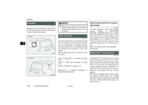
Ventilators........................................................................................... 7-02
Front automatic air conditioning......................................................... 7-03
Rear air conditioning*.........................................................................7-09
Important operation tips for the air conditioning................................ 7-11 Air purifier (with deodorizing function)............................................. 7-11
LW/MW/FM radio/CD player*.......................................................... 7-12
Handling of Discs................................................................................7-16
Audio Files (MP3/WMA/AAC)..........................................................7-17
Important Points on Safety for the Customer......................................7-21
Operation Keys................................................................................... 7-21 Listen to Radio.................................................................................... 7-24Listen to DAB*................................................................................... 7-25
Listen to Traffic Messages.................................................................. 7-27
Listen to CDs...................................................................................... 7-27
Listen to MP3s.................................................................................... 7-28
Listen to an iPod................................................................................. 7-29 Listen to Audio Files on a USB Device.............................................. 7-31To play iPod/USB memory device tracks via voice opera-
tion (vehicles with Bluetooth ®
2.0 interface)................................. 7-34
Listen to Bluetooth Audio*................................................................. 7-36
Use AUX*........................................................................................... 7-38
To listen to a disc in the Video Entertainment System (ve- hicles with Video Entertainment System)...................................... 7-39
Display Indicator................................................................................. 7-40
Audio Quality and Volume Balance Adjustment............................... 7-41
System Settings................................................................................... 7-42
Troubleshooting.................................................................................. 7-47
Antenna............................................................................................... 7-50
Link System*...................................................................................... 7-50Bluetooth ®
2.0 interface*....................................................................7-50
USB port*........................................................................................... 7-71
HDMI port*.........................................................................................7-74 Sun visors............................................................................................ 7-74
Ashtray*.............................................................................................. 7-76 Cigarette lighter*.................................................................................7-76
Accessory socket................................................................................. 7-77
Interior lamps...................................................................................... 7-78 Storage spaces..................................................................................... 7-82
Cup holder........................................................................................... 7-85 Rear shelf (3-door models)*............................................................... 7-86
Cargo area cover (5-door models)*.................................................... 7-87
Convenient hooks (5-door models)*................................................... 7-87
Luggage hooks.................................................................................... 7-88 Coat hooks...........................................................................................7-88
Installation position for warning triangle............................................ 7-89For pleasant driving
OVWE16E17
Page 207 of 404
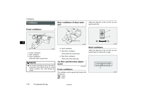
VentilatorsE00700100373
Front ventilators
1- Centre ventilators
2- Side ventilators
3- Floor ventilators* (from the centre console box)
NOTElDo not place beverages on top of the instru-
ment panel. If they splash into the air condi-
tioning ventilators, they could damage the
system.Rear ventilators (5-door mod-
els)*4-Roof ventilators5-Rear floor ventilators (from under the second seat)6-Rear floor ventilators (from side of the third seat)Air flow and direction adjust-ments
E00700200619
Front ventilators
The ventilator can be opened and closed with the dial (A).
(
) - Open
(
) - Close
Adjust the direction of the air flow by mov-
ing the knob (B).
Roof ventilators
Adjust the direction of the air flow by mov-
ing the knob (C) either left or right.
Ventilators
7-02OVWE16E1For pleasant driving7
Page 208 of 404
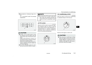
NOTElThe cool air from the ventilators may appear
as a mist.
This is due to moist air being suddenly
cooled by the air conditioning. This will
clear after a few moments.Front automatic air
conditioning E00702400165
The front air conditioning can only be used
while the engine is running.Control panel
E00702502610
1- Temperature control dial
2- Demister switch
3- MODE switch
4- OFF switch
5- Blower speed selection dial
6- AUTO switch
7- Rear window demister switch ® p. 5-50
8- Air selection switch
9- Rear fan switch* ® p. 7-10
10- Air conditioning switch11- Temperature display
12- Mode selection display
13- Rear blower operation display
14- Front blower speed displayNOTEl There is an interior air temperature sensor
(A) in the illustrated position.
Never place anything on top of the sensor,
since doing so will prevent it from function- ing properly.
Front automatic air conditioning
7-03OVWE16E1For pleasant driving7