Page 249 of 282

~ Then remove the other wheel bolts as described above.
~ Takeoff the wheel leaving the a lignment pin in
the bolt ho le ¢ (D.
Putting on th e oth er w heel
~ Lift the whee l and carefully slide it over the
alignment pin to guide it in place ¢(D.
~ Use the hexagonal socket in the screwdriver
handle to screw in and tighten all whee l bolts
sligh tly.
~ Remove the alignment pin and insert and tight
en the remaining wheel bolt slightly like the
rest .
~ Turn the jack handle counter-clockwise to lower
the vehicle until the jack is fu lly re leased.
~ Use the wheel bolt wrench to tighten all wheel
bolts firmly ¢
page 244 . Tighten them cross
wise,
from one bolt to the (approximately) op
posite one, to keep the whee l centered .
When removing or installing the whee l, the
rim could hit the brake rotor/ceramic brake
rotor* and damage the rotor. Work carefully
and have a second person help you.
(D Tips
Never use the hexagonal socket in the handle
of the screwdriver to loosen or tighten the
wheel bo lts.
- Pu ll the reversible blade from the screwdriv
er before you use the hexagonal socket in
the handle to turn the wheel bo lts.
- When mounting tires w ith
u nidirectio nal
tre ad design
make sure the tread pattern is
po inted the r ight way ¢
page 247.
-The wheel bolts should be clean and easy to
turn . Check for d irt and corrosion on the
mating surfaces of both the wheel and the
hub . Remove all dirt from these surfaces be
fo re remo unt ing the wheel.
Em ergenc y ass is tanc e
Tires with unidirectional tread design
Tires with unidirectional tread design must be
mounted with their tread pattern pointed in the
right direction .
Using a repl acement t ire w ith a tread pattern
intend ed for use in a sp ecific direction
When using a rep lacement tire with a tread pat
tern intended for use in a spec ific d irection ,
please note the follow ing:
- The direction of rotation is marked by an arrow
on the side of the tire .
- If the replacement tire has to be installed in
the incorrect direction, use the replacement tire only temporarily s ince the t ire w ill not be
ab le to achieve its optimum perfo rmance char
acter istics with rega rd to aquap lan ing, no ise
and wear.
- We recommend that you pay pa rt icu lar atten
tion to th is fact d uring wet weather and that
you adjust your speed to match road cond i
tions .
- Rep lace the flat tire w ith a new one and have it
installed on your veh icle as soon as possib le to
restore the hand ling advantages of a unidirec
tional tire.
Notes on wheel changing
Please read the information ¢ page 225, New
tires or wheels
if you a re go ing to u se a replace
ment t ire wh ich is different from the t ires on
you r vehicle .
After you change a tire:
- Check the tire pre ssure on the r epl acement
tire immed iatel y afte r in st a llat ion .
- Have th e whe el bolt tight ening torqu e
c hecked with a torque w rench as s oon as pos
s ible b y your authorized Audi de aler o r a
qualified ser vice st ation.
- With steel and allo y wheel rim s, the wheel
bolt s are co rr ectl y ti ghtened at a torque of 90
ft lb
( 1 20 Nm) .
-If you notice that the wheel bolts are corroded
and diffi cult to turn while changing a ti re ,
the y should be r eplaced before you chec k the
tightening torque. ..,.
247
Page 250 of 282

Emerg enc y assis ta nc e
-Repl ace th e flat tire with a ne w one and have
it in st a lled on you r vehicl e as s oon as poss i
ble . R emount the wheel co ve r.
Until th en, driv e with extr a care and at r educe d
s peeds .
A WARNING
-If you are going to equip your vehicle w ith
t ires or rims which differ from those which
were factory installed, then be sure to read
the informat ion¢
page 225, New tires or
wheels.
- Always make sure the damaged wheel or
even a flat tire and the jack and tool kit are
properly secured in the luggage compart
ment and are not loose in the passenger
compartment.
- In an accident or sudden ma neuver they
could fly forward, injuring anyone in the ve
hicle.
- Always store damaged wheel, jack and too ls
sec urely in the luggage compartment. Oth
erwise, in an accident or s udden maneuver
they could fly forward, causing injury to pas
sengers in the vehicle.
(D Note
Do not use commercia lly available t ire seal
ants . Otherwise , the electrical components of
the t ire pressure monito ring sys tem wi ll no
longer work properly and the sensor for the
tire press ure monitoring system will have to
be replaced by qualified workshop .
248
-
Page 251 of 282

Fuses
Replacing fuses
A fuse that has blown will have metal strips that have burned through.
Fig. 208 Drive r's side cockpit : cover
The fuses are located on front left and right of
the cockpit and behind the trim on the right side
of the luggage compartment.
.,. Switch the ignition and all electrical equipment
off .
.,. Check the following table to see which fuse be
longs to the equipment .
.,. Remove the appropriate cover.
.,. Remove the colored p lastic clip from the fuse
panel, if necessary ~
page 250, fig. 209. You
can dispose of the plastic clip .
.,. Remove the clamp from the rear side of the
cover
c> fig . 208 .
.,. Remove the fuse using the clamp .
.,. Replace the b lown fuse only with an identical
new one .
.,. Install the cover.
Fuse color identification
Color Current rating
in amps
Black 1
Purple 3
Light brown s
Brown 7.5
Red 10
Blue 15
Yellow 20
White or transparent 25
Fuses
Color Current rating
in amps
green 30
orange 40
,&_ WARNING
= -Do not repair fuses and never replace a blown
fuse with one that has a higher amp rating.
This can cause damage to the electr ical sys
tem and a fire.
(D Note
If a new fuse burns out again shortly after you
have installed it, have the electrical system
checked as soon as poss ible by an authorized
Audi dealer or authorized Audi Service Facili
ty .
Ci) Tips
-The following table does not list fuse loca
tions that are not used .
- Some of the equipment listed in the follow
ing tables applies only to certain model ver
sions or certa in optional equipment.
249
Page 252 of 282

Fuses
Driver side cockpit fuse
assignment
Fig . 209 Driver side cockp it: fuse panel with plastic bracket
Fuse panel @ (black)
No . Equipment
Electromechanical power steering, trailer
1 hitch, ionizer, switch strip, seat heating
(rear), electromechanical parking brake
Horn, climate control system, Gateway,
2 automatic dimming interior rearv iew mir·
ror
4 Park ing aid, headlight range adjustment
5 Dynamic steering, Electron
ic Stabilization
Control (ESC)
6 Headlights
7 Adaptive cruise control
8 Front passenger's seat sensors, airbag
9 Gateway
10 Engine sound, night vision
assist, garage
door opener (Home Link), parking aid
11 Video camera
image processing
12 Headlights
13 Steering column switch module
14 Terminal 15 (luggage compartment)
250
Fuse panel
@ (black)
15 Terminal 15 (engine compartment)
16 Starter
Fuse panel @ (brown)
No. Equipment
1 Infotainment
2 Infotainment
3 F
ron t passenger's seat
5 Airbag, Elect
ronic Stabilization Control
(ESC)
6 Anti·theft alarm system
7 Electromechanical parking brake
8 Inter ior lights
9
Windshield video camera heating, light/
rain sensor
10 Lumbar support (driver's seat)
11 Driver's seat
12 Electronic stabilization control
13 Horn
14 Headlights
15 Front
seat heating
16 Dynamic steering
Fuse panel © (red)
No . Equipment
1 Clutch pedal
2 Fuel pump
3 Brake light sensor
4 AdBlue (diesel
engine)/engine acoustics
5 Rear door
6 Front
door
7 Electronic stab ilizat ion control
8 Windshield wiper motor
9 Headlight washer system
10 Interior
lighting, climate control system
11 Headlights
12 Sunroof
Page 253 of 282

Front passenger side
cockpit fuse assignment
F ig. 21 0 Front passenger side cockpit: f use pane l w it h
p las tic bracket
Fuse panel @ (red )
No . Equipment
1 Infotainment, CD changer
2 I
nf otainment (disp lay)
Fuse panel @ (brown )
No . Equipment
1 Climate control system
2 Climate cont
rol sys tem (blowe r)
3 Diagnostic interface
4 Ele ctrical ignit io n lock
5 Electronic steering column lock
6 Steer ing col umn sw itch module
7 Power steering column adjustment
8 Light switch
9 Head-up display
1 0 I
nst rument cluste r
1 1 Infotainment, DVD changer
Fuses
Luggage compartment
fuse assignment
F ig . 2 1 1 Luggage compa rtment: fuse panel with p last ic
b racket
Fuse panel @ (black )
No . Equipment
1 Tra
iler hitc h/220 volt socket
2 Tra ile r hi tc h /climati zed cup holder
3
Tra iler hitch/ad justing front passenger's
seat from the rear
4 El ec tromec ha nic al pa rking brake
5 Electromec hanical parking brake
6 F ront door (front passenger's s ide)
7 Rear exterior lighting
8 Cen tral locking, closi ng a id
9 Seat heating (front)
1 1 Seat heating (rear), climate control system
12 Tra ile r hitc h
Fuse panel @ (red)
No . Equipment
1 L
eft safety belt tensioner
2 R igh t safety be lt tens ione r
3 Ad B lue tank (diesel engine)/fuel pump
4 Ad B lue tank (diesel engine)/eng ine mo unt
(gaso line e ngine)
s
Sensor-controlled l uggage compartment
li d
6 Air s uspension, adaptive dampers
7 Rear door (front passenger's side)
8 Tail lights
9 Luggage compartmen t lid
251
...
Page 254 of 282

Fuses
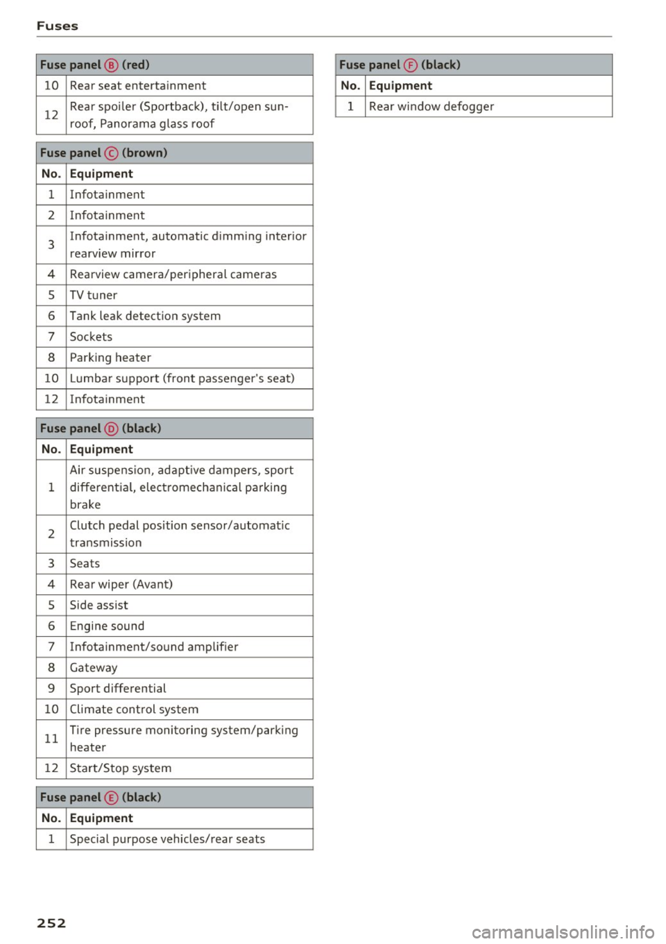
Fuse panel@ (red ) Fuse panel® (black)
10 Rear seat enterta inment No. Equipment
12
Rea r spo ile r (Sportbac k), t ilt/open sun-
roof, P anorama glass roof 1 Rear window defogge
r
Fuse panel © (brown)
No . Equipment
1 Infotainment
2 In fota inment
3
Infotainment , automatic d imm ing inter ior
rearv iew mir ror
4 Rearview camera/peripheral cameras
s TV t uner
6 Tank leak detection system
7 Sockets
8 Park ing heater
10 Lumb ar su ppo rt (front passenger 's seat)
12 In fotainment
Fuse panel @ (black)
No. Equipment
Air suspe nsio n, ad aptive dampers, sport
1 different ia l, elect romech anic al par king
brake
2
Clutch pedal position sensor/automa tic
t ransmission
3 Seats
4 Rea r wiper (Avant)
5 Side assist
6 Engine sound
7 In fota inment/so und amplif ier
8 Ga tew ay
9 Sport differential
1 0 Climate cont rol sys tem
1 1
T ire pressure monitoring system/park ing
heater
12 S tar t/S to p sys tem
Fuse panel © (black)
No. Equipment
1 Special purpose vehicles/ rear seats
252
Page 255 of 282

Emergency situations
General
This chapter is intended for trained emergency
crews and working personnel who have the nec
essary tools and equipment to perform these
ope rations.
Starting by pushing or
towing
(D Note
Veh icles with an automatic transmission can
not be started by pushing or towing.
Starting with jumper
cables
If necessary, the engine can be started by con
necting it to the battery of another vehicle .
If the engine shou ld fail to start because of a dis
charged or weak battery, the battery can be con
nected to the battery of
another vehicle, using a
pair of jumpe r cables to start the engine.
Jumper cables
Use only jumper cables of suffic iently large cross
section
to carry the starter current safely. Refer
to the manufacturer's specifications.
Use only jumper cables with
insulated term inal
clamps which are dis tinct ly marked :
plus(+) cable in most cases colored re d
minus( -) cable
in most cases colored blac k.
A WARNING
Batteries contain electricity, acid, and gas.
Any of these can cause very serious or fatal in
jury. Follow the instructions below for safe
handling of your vehicle's battery.
- Always shield your eyes and avo id leaning
over the battery whenever poss ible.
- A discharged battery can freeze at tempera
tures just below 32 °F (0 °C) . Before con
necting a jumper cable, you must thaw the
Emergency situations
frozen battery completely, otherwise it
could explode .
- Do not allow battery acid to contact eyes or
skin. Flush any contacted area with water immediately.
- Improper use of a booster battery to start a
vehicle may cause an exp losion.
- Vehicle batteries generate exp losive gases.
Keep sparks, flame and lighted cigarettes
away from batteries.
- Do not try to jump start any vehicle with a
low acid level in the battery .
- The vo ltage of the booster battery must also
have a 12-volt rating. The capacity (Ah) of
the booster battery should not be lower
than that of the discharged battery. Use of
batter ies of different voltage or substantial
ly different "Ah" rating may cause an exp lo
sion and personal injury .
- Never charge a frozen battery. Gas trapped
in the ice may cause an explosion.
- Never charge or use a battery that has been
frozen . The battery case may have be weak
ened .
- Use of batter ies of different voltage or sub
stantially different capacity (Ah) rating may
cause an exp losion and injury. The capac ity
(Ah) of the booster battery should not be
lowe r than that of the discharged battery.
- Before you check anything in the eng ine
compartment, always read and heed all
WARNINGS
r::!)page 203.
(D Note
-Applying a higher voltage booster battery
will cause expensive damage to sensitive
electronic components, such as control
units, relays, radio, etc.
- Th ere must be no electrical contact between
the vehicles as otherwise current could al
ready start to flow as soon as the positive
(+) terminals are connected.
(D Tips
The discharged battery must be properly con-
nected to the vehicle's e lectrical system. ..,.
253
Page 256 of 282

Emergency situations
When jump starting or charging the battery,
never connect the negative ground cable to
the battery negative post because the battery
manager system must be able to detect the
battery's state of charge. Always connect the
negative ground cable to the negat ive ground
post of the battery manager control unit .
Use of jumper cables
Make sure to connect the jumper cable clamps in
exactly the order described below!
Fig. 212 Engine compartment: connectors for ju mp start
cab les a nd charger
® .--l @
Fig. 213 Ju mp start ing wit h the battery o f another vehicle:
@ -boos te r battery ,® -discharged vehicle battery
The procedure described below for connecting
jumper cables is intended to provide a jump start
for your vehicle.
Vehicle with discharged battery:
• Turn off lights and accessories , move lever of
automatic transmission to N (Neutral) or P
(Park) and set parking brake .
Connect POSITIVE(+) to POSITIVE(+) (red)
• Open the red cover on the positive term inal
~ fig . 212.
254
1. Connect one end of the red positive cable on
the
jump start bolt 9 fig. 213 @ (bolt under
the red cover= "positive") of the vehicle to be
started ®·
2. Connect the other end to the positive termi-
nal@ of the booster battery @.
Connect NEGATIVE (- ) to NEGATIVE (-)
(black)
3. Connect one end of the black negative cable
to the negative term inal @ of the booster
battery @.
4 . Connect the other end to the
jump start pin
@ (bolts with hex head bolt= "negat ive") of
the vehicle to be started ®·
Starting the engine
• Start the eng ine of the vehicle with the booster
battery @. Run the engine at a moderate
speed.
• Sta rt engine w ith discharged vehicle ba ttery @
in the usual manner.
• If the engine fails to start, do not keep the
starter cranking for longer than 10 seconds.
Wait for about 30 seconds and then try again.
• With engine running, remove jumper cables
from both vehicles in the exact
reverse order.
• Close the red cover on the positive terminal.
The battery is vented to the outside to prevent gases from entering the vehicle interior . Make
sure that the jumper clamps are well connected
with their metal parts in full contact with the battery terminals.
&_ WARNING
To avoid ser ious personal injury and damage
to the vehicle, heed all warnings and instruc
tions of the jumper cable manufacturer. If in
doubt, call for road service.
- Jumper cables must be long enough so that
the vehicles do not touch.
- When connecting jumper cables, make sure
that they cannot get caug ht in any moving
parts in the engine compartment.
- Before you check anything in the engine
compartment, always read and heed all
WARNINGS
¢ page 203.