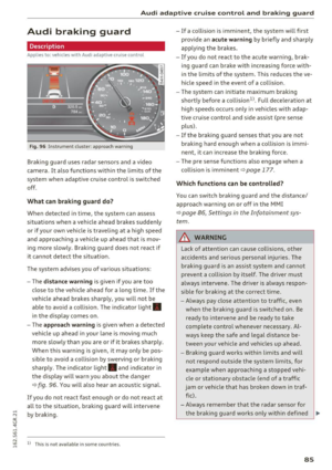
Page 25 of 282

-Always reduce your speed and drive with
special care in cold weather cond itions when
the chance of encountering icy road surfaces
increases.
(D Tips
- If the vehicle is stat iona ry, o r if you are driv
i ng at a very low speed, the temperature
s hown in the d isp lay m ight be slightly high
er t han the actual outside temperature. T his
i s caused by t he heat be ing radiated from
t h e eng ine.
- You can select the u nits used for temp era
ture, speed and othe r measureme nts in the
MM I.
- Fo r info rmation o n the a udio/video and nav
i ga tion* func tions, re fer to the s epa ra te
M MI owner's manual.
Operation
The driver information system is operated using
the buttons on the multifunc tion steering wheel.
F ig. 6 M ultifunct io n steering wheel: operating the driver
info rmation system
Fig. 7 In strume nt cluste r: o penin g the vehicle funct ions
menu
Instruments and indicator lights
Operating
.,. Switch t he igni tion on.
.,. To switch be twee n the tabs, p ress the rocker
sw itch
(D to the left o r right¢ fig. 6 .
.,. To access additiona l information below or
above, t urn the th umbwheel @down or up .
.,. To confirm a selection, p ress the thumbwheel
@.
.,. To open the submenu for an ac tive tab , press
the button [ii@.
.,. To sele ct a func tion p rogrammed to a steering
wheel button *, p re ss the butto n @ .
Opening the Vehicle functions
.,. Select the first tab with the rocker sw itch (D .
.,. Press the~ button @. The Vehicle functions
menu is disp layed ¢ fig. 7.
.,. To sele ct a men u it em, turn an d press the
t humbwhee l@ .
Resetting values to zero
.,. In the Vehicle functions menu, select On
board computer or Efficiency program .
.,. You ca n now se lec t b etw een the long-term
memory an d short- term memory .
.,. To reset the val ue s in a m emo ry, pres s and hold
the t humbwheel @for one se cond.
Assigning a function to a programmable
steering wheel button*
.,. Sele ct the I CAR ! fun ction butt on> (Car) *Sy s
tem s
contro l butto n > Vehicle settings > Steer
ing wheel button programming .
The la st fun ction sele cte d di spla ys w hen yo u
swi tch the ig nition on.
On-board computer
Fi g. 8 Instrument cluster: fuel consu mptio n display
23
Page 26 of 282

Instrumen ts and ind icator ligh ts
You can call up the following information in the
on-board computer :
-Date
- Driving time from the short-term memory
- Average consumpt ion from the short -term
memory
- Average speed from the short -term memory
- Distance driven from the shor t-term memory
- Current fuel consumption
- Short-term memory overview
- Long-term memory overview
The short-term memory collects driving informa
tion from the t ime the ignition is switched on un
til it is switched off.
If you cont inue driv ing with
in two ho urs after switching the ignition off , the
new values are included when calculating the cur
rent trip information .
Unlike the short-term memory , the long -term
memory is not erased automat ica lly . Yo u can se
lect the time period for evaluat ing trip informa
tion yourself.
For some veh icle functions , you can access the
driving information from the short-term memory
in the line
(D c:> page 22, fig . 5.
Fuel consumpti on
The current fuel consumption can be shown us
ing a bar g raph
c:> fig. 8. The average consump
tion stored in the short-term memory is also dis
p layed . If the bar is green, your vehicle is saving
fue l through one of t he following functions :
-Re cuperation : electrical ene rgy can be stored in
the battery when the vehicle is coasting or driv
ing downh ill. The bar will
move toward D.
-Cylinder on d emand sy stem* : the engine auto
matically switches 4 cylinders off when lower
power output is required and other conditions
are met. This change is not noticeable to the
passengers . The cy linders will switch on aga in
when higher power output is needed.
@ Tips
- If the vehicle battery is disconnected, all
memory va lues are erased.
24
Efficiency program
App lies to: vehicles with effic iency program
Fig. 9 In st rum en t cluster : ot her cons umers
Fig. 10 Inst rumen t cl us te r: economy tip
The eff ic iency program can help you to use less
fuel.
It shows other consumers that are using
fuel and economy tips give advice on how to drive
efficie ntly . The eff iciency p rogram receives dis
tance and consumption data from the on-board
computer .
To display the eff ic iency program, open the
Vehi
cle function s
menu and select the Efficiency pro
gram
menu item.
Other consumers
T he E n ergy con sumer s view lists other equip
ment that is currently affecting fuel consump
t ion. The d isp lay shows up to three other con
sumers @
c:>fig . 9. The equipment using the
most fue l is listed first . If mo re than th ree items
u sing fuel are switched on, the equipment that is
current ly using the most fuel is d isplayed .
A scale @also shows the current total consump-
tion of all other cons umers. .,..
Page 27 of 282

Economy tips
In certain situations, economy tips appear auto
matica lly for a short time in the efficiency pro
gram~
fig. 10. If you fo llow these economy tips,
you can reduce your vehicle's fuel consumption.
To turn an economy tip
off immediately after it
appears, press any button on the mult ifunction
steering whee l.
(D Tips
- If you erase the data in the efficiency pro
gram, the values in the on-board computer
will a lso be reset.
- Once you have turned an economy tip off, it
will only appear again after you turn the ig
nition on again .
- The economy tips are not displayed in every
instance, but rather in intervals over a peri
od of time.
Odometer
Fig . 11 Instrument cluster: odometer and reset butto n
The display of distance dr iven is shown in miles
"mi" or kilometers "km". The units of measure
ment (kilometers/miles) can be changed in the
Infotainment system.
Upper odometer
The trip odome ter shows the distance driven
since it was last reset.
It can be used to measu re
short distances. The last digit shows distances of
100 meters or 1/10 of a mile.
The trip odome ter can be reset to zero by press
ing the reset button
I ~ ].
Instruments and indicator lights
Lower odometer
The lower odomete r shows the tota l number of
kilometers or miles that the vehicle has driven.
Malfunction indicator
If there is a malfunction in the instrument clus
te r,
DEF will appear in the trip odometer display.
Have the malfunction corrected as soon as possi
ble.
Time/date display
Fig. 12 Instrument cluste r: time and date
The date, time of day and time and date format
can be set in the Infotainment system. Refer to
the Infotainment system operat ing manua l for
instructions .
When you open the driver's door, the date and
time appear in the instrument cluster display for
30 seconds.
25
Page 28 of 282

Instruments and indicator lights
Head-up display
Applies to: vehicles with Head-up display
Fig. 13 Example: indicators in the Head-up display
F ig. 14 Inst rument panel: knob for the Head-up display
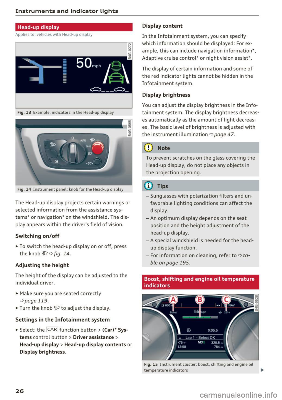
The Head-up display projects certain warnings or
selected information from the ass istance sys
tems* or navigation* on the windshie ld. The d is
p lay appears within the driver's fie ld of vision.
Switching on/off
• To switch the head-up disp lay on or off, press
the knob~
c:> fig. 14.
Adjusting the height
The height of the display can be adjusted to the
individual driver.
• Make sure yo u are seated correct ly
c:> page 119.
• Turn the knob~ to adjust the display.
Settings in the Infotainment system
• Select: the ICAR I function bu tton > (Car)* Sys
tems
control b utton > Driver assistance >
Head-up displ ay> Head-up di splay contents or
Display brightness .
26
Display content
In the Infotainment system, you can spec ify
which information shou ld be disp layed: For ex
amp le, this can include navigation information*,
Adaptive cruise contro l* or night vision assist *.
The display of certain information and some of
the red indicator lights cannot be hidden in the
Infotainment system.
Display brightness
You can adjust the display brightness in the Info
ta inment system . The display br ightness dec reas
es automatically as the amount of light decreas
es . The basic leve l of brightness is adjusted with
the instrument illumination
c:> page 47.
(D Note
To prevent scratches on the glass covering the
Head-up display, do not place any objects in
the projection opening.
(D Tips
- Sunglasses with polarization filters and un
favorable lighting conditions can affect the
display.
- An optimum display depends on the seat
position and the height adjustment of the
head-up display.
- A special windshie ld is needed for the head
up display function .
- For information on cleaning, refer to
c:> ta
ble on page 195.
Boost, shifting and engine oil temperature
indicators
Fig. 15 Instrument cluster: boost, shifting and engine oil
temperature indicators
Page 29 of 282

.. Turn the menu thumbwheel on the steering
whee l until
Lap timer appears in the instru
ment cluster display .
@ Boost pressure indicator
The current engine load (meaning the current
boost pressure) is indicated by a bar.
@ Shifting indicator
The shifting indicator is only visible when shift ing
gears in tiptronic mode
~ page 105. Green LEDs
turn on as the eng ine RPMs increase. The LE DS
flash red at speeds nea r the RPM lim it.
In vehicles with an activated Head-up display
<=>
page 26, the shifting indicator is shown in the
H ead-up display instead of the instrument clus
ter.
© Engine oil temperature indicator
If the engine oil temperature is below 60 °C, the
II symbol followed by three hyphens"---" and
the °C unit is shown.
The engine has reached its operat ing tempera
ture when the engine oil temperature is between
60
· c and 120 °C under normal driving condi
tions . The engine oil tempe rature may be higher
if there is heavy eng ine load and high tempera
tures outside . This is not a cause for concern as
long as the .
~page 16 or Ill ~page 16 indi
cator lights in the display do not blink.
Lap timer
Introduction
You can record and evaluate lap times with the
lap timer in the display <=>
page 2 7, fig. 16. The
time is measured in minutes, seconds and 1/10
seconds. The hours are also shown when the lap
time exceeds 60 minutes. The maxim um individ
ua l measurement is 99 hours. A maximum of SO
laps may be recorded.
A WARNING
Please devote your full attention to driving.
As the driver, you have complete responsibili
ty for safety in traffic. Only use the functions
in such a way that you always maintain com-
-
Instruments and indicator lights
plete control over your vehicle in all traffic sit
uations.
(D Tips
When the lap timer stopwatch is running, you
can call up the on-board computer informa
tion.
Calling up the lap timer and timing
Fig. 16 Display : Lap timer
Calling up the lap timer
.. Tu rn the thumbwheel unti l the lap timer ap-
pears.
Timing laps
.,. To start tim ing, press the thumbwheel.
.,. To stop tim ing for this lap, press the thumb
wheel again . T his also starts timing the next
round. The previous timing always moves one
line up. The lap number that corresponds to the
timing is displayed in front of the individua l
timings.
Displaying intermediate time and pausing
timing
.. To display an intermediate time, press the
thumbwheel. The timing continues to run in
the background.
.. To pause timing, press the thumbwheel.
.. To continue timing, press the thumbwheel
aga in .
If timing is paused, you can continue it later even
if you switch the ignition off.
27
Page 30 of 282

Instruments and indicator lights
Evaluating times and continuing or
resetting timing
You can evaluate the fastest, slowest and aver
age Lap times .
Fig. 17 Display: lap time evaluation
... To evaluate lap times, press the thumbwheel.
The number of laps traveled, the fastest lap
"+", the slowest lap"-" and the average lap
time "0" appears in the display .
... To continue timing for additional laps, press
the thumbwheel.
... To reset the timer to zero, press the thumb
whee l again. The lap timer is switched off now.
(D Tips
-Saved lap times cannot be individually de
l eted from the total results .
- The saved lap timer values will not be lost
after turning the ignition off.
On Board Diagnostic
System (OBD)
Malfunction Indicator Lamp (MIL)
The Malfunction Indicator Lamp (MIL) I! in the
i n str ument cluster is part of the On-Board Diag
nostic (OBD II) system.
The warning/indicator light illuminates when the
ignit ion is switched on and goes ou t after the en
g in e starts and the idle has st abilized. This indi
cates that the MIL is working properly .
If the light does not go out after the engine is
started, or illuminates wh ile you are dr iving, a
malfunct ion may exis t in the engine system.
If
28
the light illuminates, the catalyt ic converte r
could be damaged.
Continue driving
with reduced power (avoidi ng
sustai ned high speeds and/or rapid accelera
tions) and have the condition corrected. Contact
your authorized Audi dealer.
An improperly closed fuel filler cap may also
cause the MIL light to illuminate
q page 200.
On-Board Diagnostics
Fig. 18 Location of Data Link Connector (DLC)
On-Boa rd Diagnostics monitors the components
of your emission control system. Each monitored
component in your engine system has been as
s ig ned a code . In case o f a malfunct ion, the com
ponent will be identified and the fault stored as a
code in the contro l module memory.
The MIL light may also illuminate if there is a
leak in the on-board fuel vapor recovery system.
If the light illuminates after a refuelling, stop
the vehicle and make sure the fuel filler cap is properly closed
q page 200.
In order to make an accurate diagnosis, the stor
ed data can only be displayed using special diag
nostic equipment (generic scan tool for OBD) .
In order to connect the special diagnostic equip
ment, push the plug into the Data Link Connector
(DLC). The DLC is located to the right of the hood
release <=>
fig. 18.
Your authorized Audi dealer or a qua lified service
station can interpret the code and perform the
necessary repair. .,.
Page 31 of 282
A WARNING ,~
Do not use the diagnostic connector for pe r
sonal use . Incorrect usage can cause malfu nc
t ions, which can i ncrease the risk of a colli
sion !
Instruments and ind icator lights
-
29
Page 32 of 282

Opening and closing
Opening and closing
Keys
Key set
Fig. 19 Key set
@ Remote control key with mechanical key
You can centrally lock and unlock your vehicle
and start the engine w ith the master key with re
mote control. A mechanical key is integrated in
the remote control key¢
page 30.
@ Emergency key
The emergency key is not intended for constant
use. It shou ld only be used in an emergency.
Keep it in a safe place and do not carry it on your
key ring.
Key replacement
If you lose a key , contact your authorized Audi
dealer immediately to have the
lost key disab led .
Be sure to bring all your keys with you.
Personal comfort settings
If two people use one vehicle, it is recommended
that each person always uses "their own" master
key. When the ignition is switched off or when
the vehicle is locked , personal convenience set
tings for the following systems are stored and as
signed to the remote master key .
- Automatic climate contro l
- Central locking system
- Amb ience lighting*
- Seat memory*
- Parking system*
- Adaptive cruise control*
- Audi active lane assist*
30
-Audi side assist*
- Audi drive se lect
- Night vision assistant*
- Heated steering wheel*
The stored settings are automatically recalled
when you unlock the vehicle, when you open the
doors or when you switch the ignition on.
A WARNING
-
-Do not leave your vehicle unattended. Al
ways take your ignition key with you and
loc k your vehicle . Entr y by unautho rized per
sons could endanger yo u or result in theft or
damage the vehicle.
- Do not leave children unattended in the ve
hicle, especially with access to vehicle keys.
Unguarded access to the keys provides chil
dren the opport unity to start the engine
and/or activate vehicle systems s uch as the
power windows, etc. Unsupervised opera
tion of any vehicle system by ch ildren can
result in serious injury .
(D Tips
-The operation of the remote control key can
be temporarily disrupted by interference
from transmitters in the v icinity of the vehi
cle working in the same frequency range
(e.g . a cell phone, radio equipment).
- For security reasons, replacement keys are
only ava ilable from Audi dealers .
- For Declaration of Compliance to United
States FCC and Industry Canada regulations
~page 265 .
Removing the mechanical key
Fig. 20 Remote contro l maste r key : removing the mec hani -
ca l key
Ill>-