2014 NISSAN TEANA power steering
[x] Cancel search: power steeringPage 2179 of 4801
![NISSAN TEANA 2014 Service Manual
FRONT TIMING CHAIN CASEEM-181
< REMOVAL AND INSTALLATION > [VQ35DE]
C
D E
F
G H
I
J
K L
M A
EM
NP
O
• Before starting engine, check oil/fluid levels incl
uding engine coolant and engine oil. If le NISSAN TEANA 2014 Service Manual
FRONT TIMING CHAIN CASEEM-181
< REMOVAL AND INSTALLATION > [VQ35DE]
C
D E
F
G H
I
J
K L
M A
EM
NP
O
• Before starting engine, check oil/fluid levels incl
uding engine coolant and engine oil. If le](/manual-img/5/57390/w960_57390-2178.png)
FRONT TIMING CHAIN CASEEM-181
< REMOVAL AND INSTALLATION > [VQ35DE]
C
D E
F
G H
I
J
K L
M A
EM
NP
O
• Before starting engine, check oil/fluid levels incl
uding engine coolant and engine oil. If less than required
quantity, fill to the specified level. Refer to MA-11, "FOR USA AND CANADA : Fluids and Lubricants"
.
• Use procedure below to check for fuel leakage.
• Turn ignition switch ON (with engine stopped). With fuel pressure applied to fuel piping, check for fuel leak-
age at connection points.
• Start engine. With engine speed increased, check again for fuel leakage at connection points.
• Run engine to check for unusual noise and vibration. NOTE:
If hydraulic pressure inside timing chain tensioner dr ops after removal and installation, slack in the guide
may generate a pounding noise during and just after engine start. However, this is normal. Noise will stop
after hydraulic pressure rises.
• Warm up engine thoroughly to make sure there is no leak age of fuel, exhaust gas, or any oils/fluids including
engine oil and engine coolant.
• Bleed air from passages in lines and hoses, such as in cooling system.
• After cooling down engine, again check oil/fluid levels including engine oil and engine coolant. Refill to spec- ified level, if necessary.
• Summary of the inspection items:
*Power steering fluid, brake fluid, etc. Item Before starting engine Engine running After engine stopped
Engine coolant Level Leakage Level
Engine oil Level Leakage Level
Transmission/
transaxle fluid CVT Models Leakage Level/Leakage Leakage
Other oils and fluids* Level Leakage Level
Fuel Leakage Leakage Leakage
Exhaust gas — Leakage —
Revision: November 20132014 Altima NAM
Page 2219 of 4801
![NISSAN TEANA 2014 Service Manual
ENGINE ASSEMBLYEM-221
< UNIT REMOVAL AND INSTALLATION > [VQ35DE]
C
D E
F
G H
I
J
K L
M A
EM
NP
O
• Do not damage the edge of the crankshaft
position sensor (POS) or the ring gear teeth.
REMOVAL
NISSAN TEANA 2014 Service Manual
ENGINE ASSEMBLYEM-221
< UNIT REMOVAL AND INSTALLATION > [VQ35DE]
C
D E
F
G H
I
J
K L
M A
EM
NP
O
• Do not damage the edge of the crankshaft
position sensor (POS) or the ring gear teeth.
REMOVAL](/manual-img/5/57390/w960_57390-2218.png)
ENGINE ASSEMBLYEM-221
< UNIT REMOVAL AND INSTALLATION > [VQ35DE]
C
D E
F
G H
I
J
K L
M A
EM
NP
O
• Do not damage the edge of the crankshaft
position sensor (POS) or the ring gear teeth.
REMOVAL
NOTE:
When removing components such as hoses, tubes/lines, etc. , cap or plug openings to prevent fluid from spill-
ing.
1. Remove hood assembly. Refer to DLK-170, "HOOD ASSEMBLY : Removal and Installation"
.
2. Release fuel pressure. Refer to FL-5, "Inspection"
.
3. Drain engine coolant. Refer to CO-36, "Changing Engine Coolant"
.
4. Drain power steering fluid. Refer to ST-30, "Draining and Refilling"
.
5. Remove front wheels and tires (RH/LH). Refer to WT-55, "Adjustment"
.
6. Remove fender protector side covers (RH/LH). Refer to EXT-26, "FENDER PROTECTOR : Removal and
Installation".
7. Remove the engine under cover. Refer to EXT-17, "Removal and Installation"
.
8. Remove the engine room cover. Refer to EM-143, "Removal and Installation"
.
9. Remove air duct hose and resonator assembly and air cleaner case assembly with mass air flow sensor.
Refer to EM-144, "Removal and Installation"
.
10. Remove battery and battery tray. Refer to PG-74, "Removal and Installation (Battery Tray)"
.
11. Remove transmission control module. Refer to TM-183, "Removal and Installation"
.
12. Remove cowl top. Refer to EXT-24, "Removal and Installation"
.
13. Remove strut brace using power tools. Refer to FSU-19, "Exploded View"
.
14. Remove IPDM E/R. Refer to PCS-32, "Removal and Installation"
.
15. Remove the following parts: • EVAP vacuum hose
• Brake booster vacuum hose
• Heater hoses (engine side)
16. Disconnect transaxle shift control cables. Refer to TM-380, "Removal and Installation"
.
17. Remove upper and lower radiator hoses.
18. Disconnect CVT fluid cooler hoses.
19. Remove power steering reservoir, suction hose and high pressure hose.
20. Disconnect fuel hose quick connection at vehicle piping side. Refer to EM-163, "Removal and Installa-
tion".
21. Remove the front exhaust tube using power tools. Refer to EX-10, "Exploded View"
.
22. Discharge and recover the R134a refrigerant. Refer to HA-23, "Recycle Refrigerant"
.
23. Remove the A/C compressor using power tools. Refer to HA-30, "COMPRESSOR : Removal and Installa-
tion".
24. Install engine slingers into front of LH cylinder head and rear of RH cylinder head.
• (A): RH cylinder head
ALBIA0262GB
Revision: November 20132014 Altima NAM
Page 2221 of 4801
![NISSAN TEANA 2014 Service Manual
ENGINE ASSEMBLYEM-223
< UNIT REMOVAL AND INSTALLATION > [VQ35DE]
C
D E
F
G H
I
J
K L
M A
EM
NP
O
• Start engine. With engine speed increased, check again for fuel leakage at connection points.
� NISSAN TEANA 2014 Service Manual
ENGINE ASSEMBLYEM-223
< UNIT REMOVAL AND INSTALLATION > [VQ35DE]
C
D E
F
G H
I
J
K L
M A
EM
NP
O
• Start engine. With engine speed increased, check again for fuel leakage at connection points.
�](/manual-img/5/57390/w960_57390-2220.png)
ENGINE ASSEMBLYEM-223
< UNIT REMOVAL AND INSTALLATION > [VQ35DE]
C
D E
F
G H
I
J
K L
M A
EM
NP
O
• Start engine. With engine speed increased, check again for fuel leakage at connection points.
• Run engine to check for unusual noise and vibration. NOTE:
If hydraulic pressure inside timing chain tensioner dr ops after removal and installation, slack in the guide
may generate a pounding noise during and just after engine start. However, this is normal. Noise will stop
after hydraulic pressure rises.
• Warm up engine thoroughly to make sure there is no leak age of fuel, exhaust gas, or any oils/fluids including
engine oil and engine coolant.
• Bleed air from passages in lines and hoses, such as in cooling system.
• After cooling down engine, again check oil/fluid levels including engine oil and engine coolant. Refill to spec- ified level, if necessary.
• Summary of the inspection items:
*Power steering fluid, brake fluid, etc. Item Before starting engine Engine running After engine stopped
Engine coolant Level Leakage Level
Engine oil Level Leakage Level
Transmission/
transaxle fluid CVT Models Leakage Level/Leakage Leakage
Other oils and fluids* Level Leakage Level
Fuel Leakage Leakage Leakage
Exhaust gas — Leakage —
Revision: November 20132014 Altima NAM
Page 2460 of 4801
FAX-8
< REMOVAL AND INSTALLATION >
FRONT WHEEL HUB
REMOVAL AND INSTALLATION
FRONT WHEEL HUB
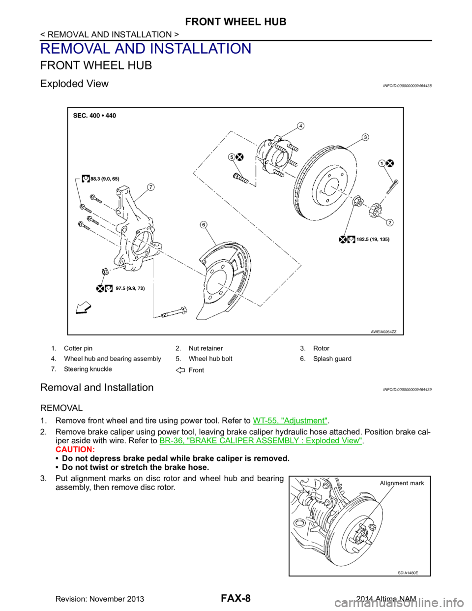
Exploded ViewINFOID:0000000009464438
Removal and InstallationINFOID:0000000009464439
REMOVAL
1. Remove front wheel and tire using power tool. Refer to WT-55, "Adjustment".
2. Remove brake caliper using power tool, leaving brak e caliper hydraulic hose attached. Position brake cal-
iper aside with wire. Refer to BR-36, "BRAKE CALIPER ASSEMBLY : Exploded View"
.
CAUTION:
• Do not depress brake pedal while brake caliper is removed.
• Do not twist or stretch the brake hose.
3. Put alignment marks on disc rotor and wheel hub and bearing assembly, then remove disc rotor.
1. Cotter pin 2. Nut retainer 3. Rotor
4. Wheel hub and bearing assembly 5. Wheel hub bolt 6. Splash guard
7. Steering knuckle Front
AWEIA0264ZZ
SDIA1480E
Revision: November 20132014 Altima NAM
Page 2461 of 4801
FRONT WHEEL HUBFAX-9
< REMOVAL AND INSTALLATION >
CEF
G H
I
J
K L
M A
B
FA X
N
O P
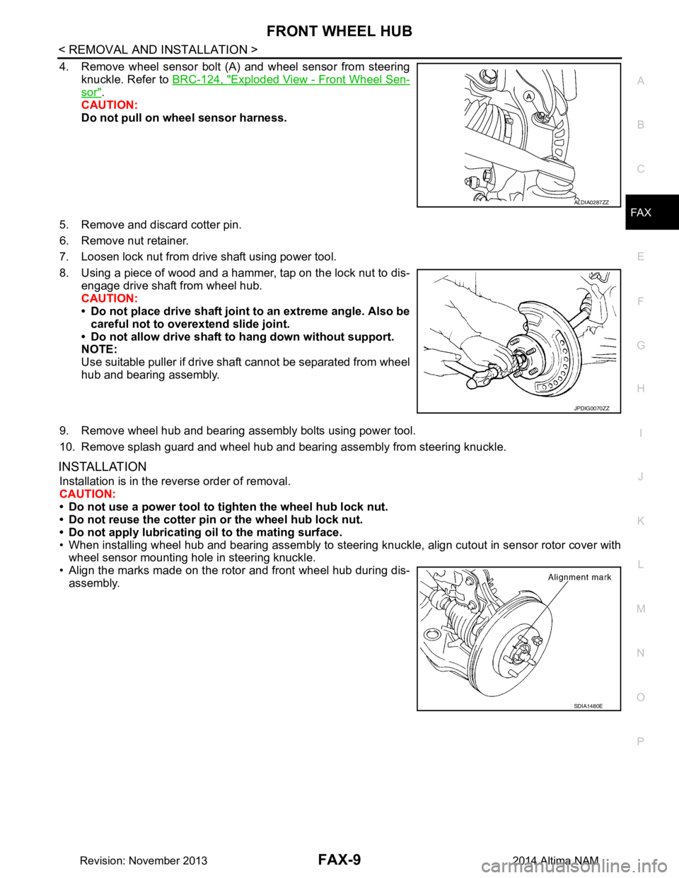
4. Remove wheel sensor bolt (A) and wheel sensor from steering knuckle. Refer to BRC-124, "Exploded View - Front Wheel Sen-
sor".
CAUTION:
Do not pull on wheel sensor harness.
5. Remove and discard cotter pin.
6. Remove nut retainer.
7. Loosen lock nut from drive shaft using power tool.
8. Using a piece of wood and a hammer, tap on the lock nut to dis- engage drive shaft from wheel hub.
CAUTION:
• Do not place drive shaft joint to an extreme angle. Also be careful not to over extend slide joint.
• Do not allow drive shaft to hang down without support.
NOTE:
Use suitable puller if drive shaft cannot be separated from wheel
hub and bearing assembly.
9. Remove wheel hub and bearing assembly bolts using power tool.
10. Remove splash guard and wheel hub and bearing assembly from steering knuckle.
INSTALLATION
Installation is in the reverse order of removal.
CAUTION:
• Do not use a power tool to tighten the wheel hub lock nut.
• Do not reuse the cotter pin or the wheel hub lock nut.
• Do not apply lubricating oil to the mating surface.
• When installing wheel hub and bearing assembly to steering knuckle, align cutout in sensor rotor cover with wheel sensor mounting hole in steering knuckle.
• Align the marks made on the rotor and front wheel hub during dis- assembly.
ALDIA0287ZZ
JPDIG0070ZZ
SDIA1480E
Revision: November 20132014 Altima NAM
Page 2462 of 4801
FAX-10
< REMOVAL AND INSTALLATION >
FRONT DRIVE SHAFT
FRONT DRIVE SHAFT
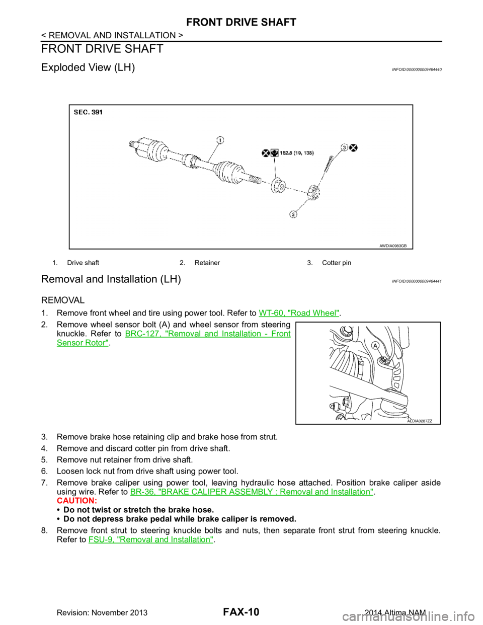
Exploded View (LH)INFOID:0000000009464440
Removal and Installation (LH)INFOID:0000000009464441
REMOVAL
1. Remove front wheel and tire using power tool. Refer to WT-60, "Road Wheel".
2. Remove wheel sensor bolt (A) and wheel sensor from steering knuckle. Refer to BRC-127, "Removal and Installation - Front
Sensor Rotor".
3. Remove brake hose retaining clip and brake hose from strut.
4. Remove and discard cotter pin from drive shaft.
5. Remove nut retainer from drive shaft.
6. Loosen lock nut from drive shaft using power tool.
7. Remove brake caliper using power tool, leaving hy draulic hose attached. Position brake caliper aside
using wire. Refer to BR-36, "BRAKE CALIPER ASSEMBLY : Removal and Installation"
.
CAUTION:
• Do not twist or stretch the brake hose.
• Do not depress brake pedal while brake caliper is removed.
8. Remove front strut to steering knuckle bolts and nut s, then separate front strut from steering knuckle.
Refer to FSU-9, "Removal and Installation"
.
1. Drive shaft 2. Retainer 3. Cotter pin
AWDIA0983GB
ALDIA0287ZZ
Revision: November 20132014 Altima NAM
Page 2464 of 4801
FAX-12
< REMOVAL AND INSTALLATION >
FRONT DRIVE SHAFT
1. Check CVT fluid level and leakage. Refer to TM-84, "Adjustment" (REOF10D), TM-286, "Adjustment"
(REOF10E).
2. Check wheel alignment. Refer to FSU-7, "Inspection and Adjustment"
.
3. Adjust the neutral position of the steering angle sensor. Refer to BRC-58, "Work Procedure"
.
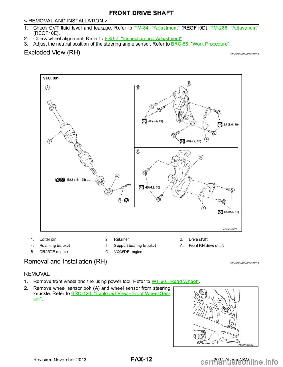
Exploded View (RH)INFOID:0000000009464442
Removal and Installation (RH)INFOID:0000000009464443
REMOVAL
1. Remove front wheel and tire using power tool. Refer to WT-60, "Road Wheel".
2. Remove wheel sensor bolt (A) and wheel sensor from steering knuckle. Refer to BRC-124, "Exploded View - Front Wheel Sen-
sor".
1. Cotter pin 2. Retainer 3. Drive shaft
4. Retaining bracket 5. Support bearing bracket A. Front RH drive shaft
B. QR25DE engine C. VQ35DE engine
ALDIA0371ZZ
ALDIA0287ZZ
Revision: November 20132014 Altima NAM
Page 2465 of 4801
FRONT DRIVE SHAFTFAX-13
< REMOVAL AND INSTALLATION >
CEF
G H
I
J
K L
M A
B
FA X
N
O P
3. Remove brake hose retaining clip and brake hose from strut.
4. Remove and discard cotter pin from drive shaft.
5. Remove nut retainer from drive shaft.
6. Loosen lock nut from drive shaft using power tool.
7. Remove brake caliper using power tool, leaving hy draulic brake hose attached. Position caliper aside
using wire. Refer to BR-36, "BRAKE CALIPER ASSEMBLY : Removal and Installation"
.
CAUTION:
• Do not twist or stretch the brake hose.
• Do not depress brake pedal while brake caliper is removed.
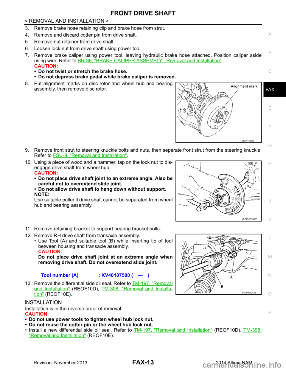
8. Put alignment marks on disc rotor and wheel hub and bearing assembly, then remove disc rotor.
9. Remove front strut to steering knuckle bolts and nuts, then separate front strut from the steering knuckle.
Refer to FSU-9, "Removal and Installation"
.
10. Using a piece of wood and a hammer, tap on the lock nut to dis- engage drive shaft from wheel hub.
CAUTION:
• Do not place drive shaft joint to an extreme angle. Also be careful not to over extend slide joint.
• Do not allow drive shaft to hang down without support.
NOTE:
Use suitable puller if drive shaft cannot be separated from wheel
hub and bearing assembly.
11. Remove retaining bracket to support bearing bracket bolts.
12. Remove RH drive shaft from transaxle assembly. • Use Tool (A) and suitable tool (B) while inserting tip of tool
between housing and transaxle assembly.
CAUTION:
Do not place drive shaft join t at an extreme angle when
removing drive shaft. Do not overextend slide joint.
13. Remove the differential side oil seal. Refer to TM-197, "Removal
and Installation" (REOF10D), TM-398, "Removal and Installa-
tion" (REOF10E).
INSTALLATION
Installation is in the reverse order of removal.
CAUTION:
• Do not use power tools to tighten wheel hub lock nut.
• Do not reuse the cotter pin or the wheel hub lock nut.
• Install a new differential side oil seal. Refer to TM-197, "Removal and Installation"
(REOF10D), TM-398,
"Removal and Installation" (REOF10E).
SDIA1480E
JPDIG0070ZZ
Tool number (A) : KV40107500 ( — )
JPDIF0004ZZ
Revision: November 20132014 Altima NAM