Page 2544 of 4801

GI-16
< HOW TO USE THIS MANUAL >
ABBREVIATIONS
P
R
S
T
U
V
OL Open loop
OSS Output shaft speed
ABBREVIATION DESCRIPTION P/S Power steering
PBR Potentio balance resistor
PCV Positive crankcase ventilation
PNP Park/Neutral position PSP Power steering pressurePTC Positive temperature coefficient
PTO Power takeoff
PWM Pulse width modulation
ABBREVIATION DESCRIPTION RAM Random access memoryRAS Rear active steer RH Right-hand
ROM Read only memory RPM Engine speed RR Rear
ABBREVIATION DESCRIPTION SAE Society of Automotive Engineers, Inc.
SCK Serial clock
SDS Service Data and Specifications SRT System readiness testSST Special Service Tools
ABBREVIATION DESCRIPTION TC Turbocharger
TCM Transmission control module TCS Traction control system
TCU Telematics communication unit TP Throttle position
TPMS Tire pressure monitoring system TSS Turbine shaft speed
TWC Three way catalytic converter
ABBREVIATION DESCRIPTION USS Uphill start support
ABBREVIATION DESCRIPTION VCM Vehicle control moduleVDC Vehicle dynamics control system
ABBREVIATION DESCRIPTION
Revision: November 20132014 Altima NAMRevision: November 20132014 Altima NAM
Page 2637 of 4801

COMPRESSORHA-31
< REMOVAL AND INSTALLATION >
C
D E
F
G H
J
K L
M A
B
HA
N
O P
4. Remove the drive belt. Refer to EM-19, "Removal and Installation" (QR25DE), or EM-134, "Removal and
Installation" (VQ35DE).
5. Reposition the power steering line. Refer to ST-40, "Exploded View"
.
6. Disconnect the A/C pipes from the compressor. CAUTION:
Cap or wrap the joint of the A/C pipes with suitable material such as vinyl tape to avoid the entry of
air.
7. Disconnect the harness connector from the compressor.
8. Remove the compressor bolts and the compressor.
INSTALLATION
Installation is in the reverse order of removal.
CAUTION:
• Do not reuse the O-rings.
• Apply A/C compressor oil to th e new O-rings for installation.
• After charging the A/C refriger ant, check for leaks. Refer to HA-21, "Leak Test"
.
• Tighten the compressor bolts to specification. Refer to HA-30, "COMPRESSOR : Exploded View"
.
MAGNET CLUTCH
MAGNET CLUTCH : Removal and InstallationINFOID:0000000009463938
REMOVAL
1. Remove the front under cover. Refer to EXT-28, "Removal and Installation".
2. Partially remove the fender protector (RH). Refer to EXT-26, "FENDER PROTECTOR : Removal and
Installation".
3. Remove the drive belt. Refer to EM-19, "Removal and Installation"
(QR25DE), or EM-134, "Removal and
Installation" (VQ35DE).
4. Remove the center bolt by holding the clutch disc steady using a suitable tool.
5. Remove the clutch disc and shims. CAUTION:
Retain all the shim s for installation.
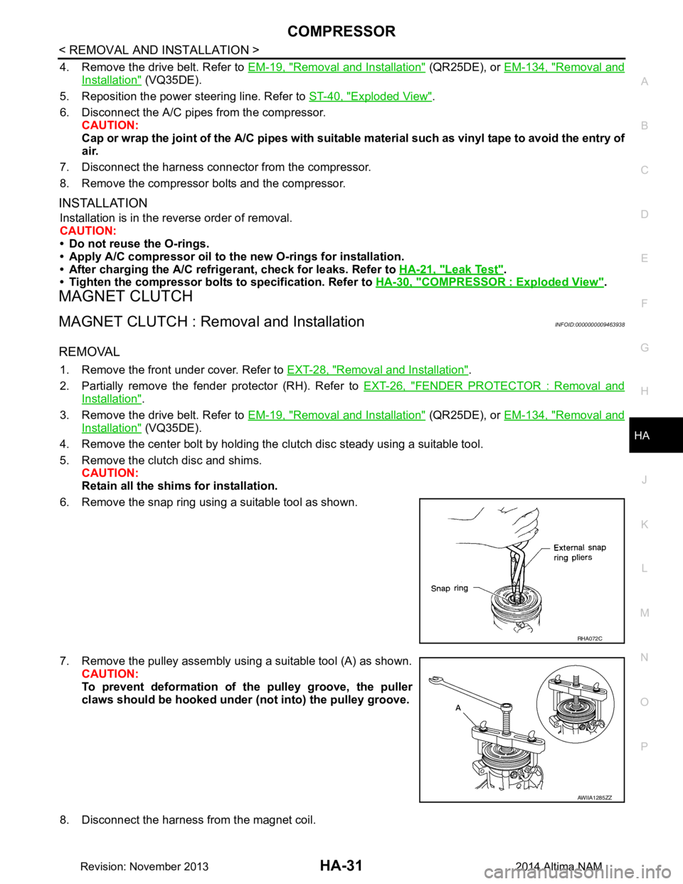
6. Remove the snap ring using a suitable tool as shown.
7. Remove the pulley assembly using a suitable tool (A) as shown. CAUTION:
To prevent deformation of th e pulley groove, the puller
claws should be hooked under (not into) the pulley groove.
8. Disconnect the harness from the magnet coil.
RHA072C
AWIIA1285ZZ
Revision: November 20132014 Altima NAM
Page 2641 of 4801

COOLER PIPE AND HOSEHA-35
< REMOVAL AND INSTALLATION >
C
D E
F
G H
J
K L
M A
B
HA
N
O P
Installation is in the reverse order of removal.
CAUTION:
• Do not reuse O-rings.
• Apply A/C oil to the new O-rings.
• After charging refrigerant, check for leaks. Refer to HA-21, "Leak Test"
.
HIGH-PRESSURE FLEXIBLE HOSE
HIGH-PRESSURE FLEXIBLE HOSE : Removal and InstallationINFOID:0000000009463941
REMOVAL
1. Discharge the refrigerant. Refer to HA-23, "Recycle Refrigerant".
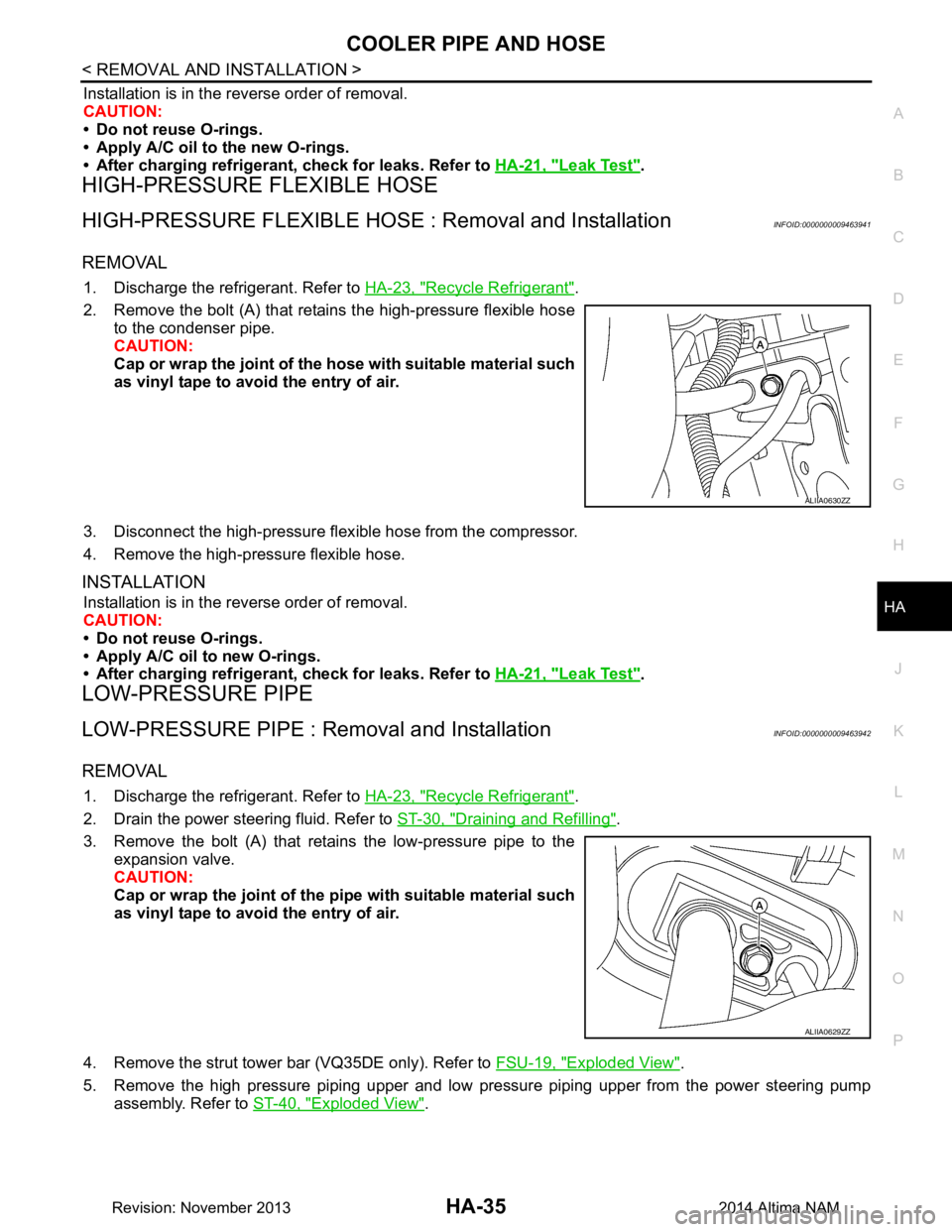
2. Remove the bolt (A) that retains the high-pressure flexible hose to the condenser pipe.
CAUTION:
Cap or wrap the joint of the ho se with suitable material such
as vinyl tape to avoid the entry of air.
3. Disconnect the high-pressure flex ible hose from the compressor.
4. Remove the high-pressure flexible hose.
INSTALLATION
Installation is in the reverse order of removal.
CAUTION:
• Do not reuse O-rings.
• Apply A/C oil to new O-rings.
• After charging refrigerant, check for leaks. Refer to HA-21, "Leak Test"
.
LOW-PRESSURE PIPE
LOW-PRESSURE PIPE : Re moval and InstallationINFOID:0000000009463942
REMOVAL
1. Discharge the refrigerant. Refer to HA-23, "Recycle Refrigerant".
2. Drain the power steering fluid. Refer to ST-30, "Draining and Refilling"
.
3. Remove the bolt (A) that retains the low-pressure pipe to the expansion valve.
CAUTION:
Cap or wrap the joint of the pi pe with suitable material such
as vinyl tape to avoid the entry of air.
4. Remove the strut tower bar (VQ35DE only). Refer to FSU-19, "Exploded View"
.
5. Remove the high pressure piping upper and low pressure piping upper from the power steering pump assembly. Refer to ST-40, "Exploded View"
.
ALIIA0630ZZ
ALIIA0629ZZ
Revision: November 20132014 Altima NAM
Page 2642 of 4801
HA-36
< REMOVAL AND INSTALLATION >
COOLER PIPE AND HOSE
6. Remove the bolt (A) that retains the low-pressure pipe to thelow-pressure flexible hose.
7. Remove the low-pressure pipe.
INSTALLATION
Installation is in the reverse order of removal.
CAUTION:
• Do not reuse O-rings.
• Apply A/C oil to new O-rings.
• After charging refrigerant, check for leaks. Refer to HA-21, "Leak Test"
.
HIGH-PRESSURE PIPE
HIGH-PRESSURE PIPE : Removal and InstallationINFOID:0000000009463943
REMOVAL
1. Discharge the refrigerant. Refer to HA-23, "Recycle Refrigerant".
2. Remove the power steering pump assembly. Refer to ST-38, "Removal and Installation"
.
3. Remove the strut tower bar. Refer to FSU-19, "Exploded View"
.
4. Remove the coolant overflow reservoir tube (A).
5. Remove the coolant overflow reservoir bolt (B).
6. Remove the coolant overflow reservoir (1).
ALIIA0627ZZ
ALIIA0621ZZ
Revision: November 20132014 Altima NAM
Page 2678 of 4801
![NISSAN TEANA 2014 Service Manual
A/C AUTO AMP.HAC-29
< ECU DIAGNOSIS INFORMATION > [AUTOMATIC AIR CONDITIONER]
C
D E
F
G H
J
K L
M A
B
HAC
N
O P
Te r m i n a l N o . (Wire color) Description
ConditionVa l u e
(Approx.)
+ − Sign NISSAN TEANA 2014 Service Manual
A/C AUTO AMP.HAC-29
< ECU DIAGNOSIS INFORMATION > [AUTOMATIC AIR CONDITIONER]
C
D E
F
G H
J
K L
M A
B
HAC
N
O P
Te r m i n a l N o . (Wire color) Description
ConditionVa l u e
(Approx.)
+ − Sign](/manual-img/5/57390/w960_57390-2677.png)
A/C AUTO AMP.HAC-29
< ECU DIAGNOSIS INFORMATION > [AUTOMATIC AIR CONDITIONER]
C
D E
F
G H
J
K L
M A
B
HAC
N
O P
Te r m i n a l N o . (Wire color) Description
ConditionVa l u e
(Approx.)
+ − Signal name Input/
Output
1
(L) —CAN-H Input/
Output ——
2
(B) —Ground — — —
3
(SB) Ground Battery power supply Input Ignition switch OFF Battery voltage
4
(BR) Ground TX FR Output Ignition switch ON 0 – 5 V
7
(L) Ground Ambient sensor signal Input Ignition switch ON 0 – 4.8 V
Output voltage varies with ambi- ent temperature
8
*1
(BR) Ground
Heated steering wheel
switch signal InputIgnition
switch ON Heated steer-
ing wheel
switch: While
pressing 0 V
Other than the
above 12 V
9
(G) Ground Sunload sensor signal Input Ignition switch ON 0 – 4.8 V
Output voltage varies with sun- load amount
13
(P) Ground IGN 2 Input Ignition switch ON Battery voltage
15
(Y) Ground RR DEF switch Output Defroster
switch OFF 0 V
ON 12 V
16
(G) Ground Each door motor LIN signal
Input/
Output Ignition switch ON
17
(W) GroundEach door motor power
supply Output Ignition switch ON 12 V
18
(P) Ground
Front blower motor control
signal Output• Ignition switch ON
• Front fan speed: 1st
speed (manual)
20
*1
(P) Ground
Heated steering wheel relay
control signal OutputIgnition
switch ON Within 30 sec-
onds after
turning ON
the heated
steering
switch. 0 V
Other than the
above 12 V
21
(P) —CAN-L Input/
Output ——
SJIA1453J
JSIIA0096ZZ
Revision: November 20132014 Altima NAMRevision: November 20132014 Altima NAM
Page 2679 of 4801
![NISSAN TEANA 2014 Service Manual
HAC-30
< ECU DIAGNOSIS INFORMATION >[AUTOMATIC AIR CONDITIONER]
A/C AUTO AMP.
*1: With heated steering wheel
DTC Inspection Priority ChartINFOID:0000000009463105
If some DTCs are displayed at the sam NISSAN TEANA 2014 Service Manual
HAC-30
< ECU DIAGNOSIS INFORMATION >[AUTOMATIC AIR CONDITIONER]
A/C AUTO AMP.
*1: With heated steering wheel
DTC Inspection Priority ChartINFOID:0000000009463105
If some DTCs are displayed at the sam](/manual-img/5/57390/w960_57390-2678.png)
HAC-30
< ECU DIAGNOSIS INFORMATION >[AUTOMATIC AIR CONDITIONER]
A/C AUTO AMP.
*1: With heated steering wheel
DTC Inspection Priority ChartINFOID:0000000009463105
If some DTCs are displayed at the same time, perfo
rm inspections one by one based on the following priority
chart.
22
(B) —Ground — — —
23
(G) Ground Ignition power supply Input Ignition switch ON Battery voltage
24
(V) Ground RX FR Input Ignition switch ON 0 – 5 V
26
(W) — Sensor ground — — —
27
(G) Ground In-vehicle sensor signal Input Ignition switch ON 0 – 4.8 V
Output voltage varies with in-vehi-
cle temperature
28
(P) Ground Intake sensor signal Input Ignition switch ON 0 – 4.8 V
Output voltage varies with front evaporator fin temperature
35
(P) Ground RR DEF feedback Input
Defroster
switch OFF 0 V
ON 12 V
37
(B) — ACTR Ground — — —
40
(G) Ground
ECV (electrical control
valve) control signal Output• Ignition switch ON
• Active test (HVAC test):
MODE 1
Te r m i n a l N o .
(Wire color) Description
ConditionVa l u e
(Approx.)
+ − Signal name Input/
Output
SJIA1607E
Revision: November 20132014 Altima NAMRevision: November 20132014 Altima NAM
Page 2972 of 4801
LAN
HOW TO USE THIS SECTIONLAN-23
< HOW TO USE THIS MANUAL > [CAN]
C
D E
F
G H
I
J
K L
B
A
O P
N
HOW TO USE THIS MANUAL
HOW TO USE THIS SECTION
InformationINFOID:0000000009461404
• “CAN” of LAN Section describes information
peculiar to a vehicle and inspection procedures.
• For trouble diagnosis procedure, refer to LAN-18, "Trouble Diagnosis Flow Chart"
of “CAN FUNDAMEN-
TA L ” .
Abbreviation ListINFOID:0000000009461405
Unit name abbreviations in CONSULT CAN diagnosis and in this section are as per the following list.
Abbreviation Unit name
A-BAG Air bag diagnosis sensor unitABS ABS actuator and electric unit (control unit)
AV AV control unit
AV M I T S c o n t r o l u n i t
BCM BCM DLC Data link connector
ECM ECM EPS Power steering control module
HVAC A/C auto amp.
IPDM-E IPDM E/R M&A Combination meter
STRG Steering angle sensor TCM TCM
Revision: November 20132014 Altima NAMRevision: November 20132014 Altima NAM
Page 2975 of 4801
LAN-26
< SYSTEM DESCRIPTION >[CAN]
COMPONENT PARTS
SYSTEM DESCRIPTION
COMPONENT PARTS
Component Parts LocationINFOID:0000000009461409
Air bag diagnosis sensor unit AV control unit ITS control unit
ABS actuator and elec tric unit (con-
trol unit) Power steering control module TCM
ECM IPDM E/R A/C auto amp.
Data link connector BCM Combination meter
Steering angle sensor
AWMIA1288ZZ
Revision: November 20132014 Altima NAMRevision: November 20132014 Altima NAM