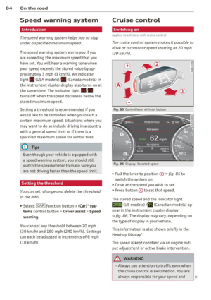
Page 25 of 306

Instrument s and warnin g/indic ator ligh ts 23
!§!10 $ Defective light bulb warning
II -If the indicator light turns on, a bulb has
fa iled. The message indicates the location of
the bulb .
[!ll-if a rear fog lamp has fa iled, the indicator
l ight tu rns on to indicate the location on the
veh icle.
Vehicle light s: malfunc tion
If the message appears, there is a malfunc
tion in the headlights or light switch .
Drive to your authorized Audi dea ler immedi
ately to have the malfunction corrected .
A WARNING
-Light bu lbs are pressurized and could ex
plode while they are being changed caus
ing serious persona l injury.
- Work w ith due care when handling the
high-voltage section of gas discharge
(xenon) lights. Fa ilure to do so could re
sult in death or se rious inj ury.
(D Tips
Have the bulb replaced or the connection
repaired by you r aut horized Aud i Service
department.
~(D Headlight range control
II H eadl ight range c ontr ol: d efective!
If the symbol illuminates, the headlight range
control is no longer working properly . Have
the system checked and repa ired at your Aud i
dealer .
~O Adaptive Light
Appl ies to vehicles: with Ada ptive Light
m;J Audi adaptiv e ligh t: sy stem fault
If the indicator light turns on and th is mes
sage appears, the re is a malfunction in the
adapt ive l ight system. The headlights still
function. Go to an authorized dealersh
ip to have the
headlights or the control unit for the Adaptive
Light repaired.
@) Light/rain sensor
II A utomatic headlights /automatic wipers :
s y ste m fault
If the indicator light turns on and this mes
sage appears, the light/rain sensor is not
funct ioning correct ly.
Fo r safety reasons the low beams are t urned
on pe rmanently with the switch in
AUTO.
However, you can continue to turn the lights
on and off us ing the light switch. You can st ill
control all functions that are independent of
the ra in sensor through the w indshield wiper
lever .
Contact your authorized Audi dealer as soon
as possible to have the problem corrected .
rI Sport differential
App lies to vehicles: wit h sport differential
(II Sport differential: sy stem f ault
There is a malfunction with the sport d ifferen
tial.
Drive to your authorized A udi dealer immedi
ate ly to have the malfunction corrected.
(II Sport differ ential: o verhea ting
The transm iss ion tempe rature has increased
s ignifica ntly due to the sporty d riving manner.
D rive in a less sporty ma nner un til the tem
perature re turns to the normal range and the
indicator light switches of.
A WARNING
Contact your author ized Audi dealer or a
q ualified workshop if the spo rt differential
is faulty or malfunct ioning. The repair
must be performed by trained personnel
using the correct oil in order to ensure
safety .
-
Page 26 of 306

24 Instr uments and warning/indicator lights
¢¢Turn signals
The indicator light blinks when you use either
turn signal .
Whenever you use the left II or the rig ht a
turn signal, the indicator light blinks. When
you use the emergency flashers, both indica
tor lights flash.
If one of the turn signal light bulbs burn out,
the turn signal will blink twice as fast as nor
mal. Carefully drive to your authorized Audi
dealer immediately to have the malfunction
corrected. The indicator light does not indi
cate a malfunction if a turn signal on the trail
er or on the vehicle fails in trailer towing
mode.
@ Tips
For more informat ion on the turn signals,
refer to
c::> page 46.
CRUISE/" (') Cruise control
The warning/indicator light (ij;(l)~i~ (USA mod
e ls)/ il (Canada mode ls) illuminates when
the cruise contro l is activated
c::> page 84.
Driver information
display
Overview
Fig. 4 Driver information system in the instrument
cluster
Fig. 5 Disp lay: example of the informat ion line
The driver information system contains infor
mation ® that is disp layed on tabs@
c::> fig. 4. The following content is possible de
pending on veh icle equipment:
@ ®
Tab Content
1 Vehicle functions :
On-board computer c::> page 26
Efficiency program* c::> page 26
Digital speedometer
Cruise control*
c::> page 84
Adaptive c ruise control and braking
guard*
c::> page 86
Audi active lane assist* c::> page 95
Display darkened
2 Indicator lights and messages
Warning when a door, the hood or
the rea r lid is not closed
Service interval display
c::> page 28
Speed warning system c::> page 84
3 Night vision assistant* c::> page 105
4 Audio/video
s Telephone*
6 Navigation*
The second and third tabs a re only vis ible if at
least one indicator lig ht or message is shown
or if that system is switched on.
T he status line © is located in the bottom
part of the display
c::> fig. 4. It displays the ex
terior temperature , time, se lector lever posi-
tion, trip odometer and odometer. ..,.
Page 27 of 306

Instruments and warning/indicator lights 25
For some vehicle functions, you can access the
trip information from the temporary memory
¢
page 26 in the line CD¢ fig. 5.
.&_ WARNING
-
- Never rely exclusively on the outside
temperature display to determine if a
road surface is icy or not . Keep in mind
that road surfaces, especially bridges
and overpasses, could be ice covered and
slippery even at an outside temperature above
41 °F (+5 °().
- Always remember, even if the "snow
flake" symbol (ice warning) does not ap
pear in the display, black ice could be on
the road.
- Always reduce your speed and drive with
special care in cold weather conditions
when the chance of encountering icy
road surfaces increases.
@ Tips
- At temperatures below 14 °F (+ 5 °C) a
snowflake symbol appears ahead of the
temperature display. It is intended to re
mind the driver to pay special attention
to
ice on the road ¢ ,&. . If the vehicle is
stationary, or if you are driving at a very
low speed, the temperature shown in the
display might be slightly higher than the
actual outside temperature . This is
caused by the heat being radiated from
the engine .
- You can select the units used for temper
ature, speed and other measurements in
the MMI.
- For information on the audio/video and
navigation* functions, refer to the sepa
rate MMI owner's manual.
Operation
The driver information system is operated us
ing the buttons on the multifunction steering
wheel.
Fig. 6 Multif unctio n steerin g wh eel: operat in g th e driv
er informat ion sys te m
Fig . 7 Dr iver informat ion syste m: o penin g the ve hicle
fu nctio ns me nu
Operating concept
"'Switch the ignition on .
"'To switch between the tabs, press the rocker
switch CD to the left or right ¢
fig. 6.
"'To access additional information below or
above, rotate the thumbwheel @down or
up.
"' To confirm a selection, press the thumb
wheel @.
"' Press the
Iii button @ to open a sub menu
for an active tab .
"'Press the button @ to access a function for
the programmable steering wheel button* .
Accessing Vehicle functions
"'Select the first tab with the rocker switch
CD -
.. Press the button
liJ@. The Vehicle func
tions
menu appears ¢ fig. 7.
"'To select a menu item, turn and press the
thumbwheel @.
Page 28 of 306

26 Instruments and warning /indicator lights
Resetting values to zero
.,. Se lect t he on -board computer / Efficien cy
program
men u item in the Vehicle func
tions
menu.
.,. You can now select between the long-term
memory and short -term memory .
.,. To reset the values i n a memory, press and
ho ld the thumbwhee l@ for one second .
Assigning a function to the
programmable steering wheel button*
.,. Se lect : ICAR !funct io n button> (Car )* sys-
tems
control button > Vehicle settings >
Ste ering wh eel button .
The last function se lected displays when y ou
switch the ignition on.
On-board computer
You can call up the following information in the on -board computer:
- D ate
- Drivi ng time ( h) from t he s ho rt- term memo-
ry
- Ave rag e consumption in MPG (l/ 100 km)
from the sho rt-term memo ry
- Ave rag e speed in mph (km/h) from the
s h ort-term memo ry
- Distance d riven in m iles (km) from the
sho rt-term me mory
- C urrent fuel co nsumption in MPG (l/100
k m)
- Sho rt-term memo ry overview
- Long-term memory overview
The s ho rt-term memo ry co llects driving i nfo r
mat io n from the time the ignit ion is switched
on until it is switched off. If yo u continue dr iv
ing within two hours after switching the igni
tion off, the new val ues a re i ncluded when cal
culating the cu rrent trip informa tion .
Unlike the short-term memory, the long-term
memory is not erased automatica lly. You can
select the time period for evaluat ing trip in
formation yo urse lf.
For some veh icle functions, you can access the
tr ip i nformat io n from the tempora ry memory
i n the line
(D ¢ page 24 , fig. 5.
The current fue l cons umption can be d is
played using a ba r
¢page 27, fig . 10. The
average cons umption (mpg) stored in the
short-term memo ry is also displayed. E lectri
ca l energy can be sto red in the battery when
t h e vehicle is coasting or dr iving dow nhill (re
c u pera tion) . The bar w ill move toward
Cl .
Efficiency program
The efficiency program can he lp y ou to use
less fuel.
It evaluates driving information in
reference to f uel consumption and shows ot h
er equipment influencing consumption as well
as shift recomme ndat ions .
¢ page 26. Fu el
eco nomy m essages
<=:> page 2 7 provide t ips
f o r efficient d riving. The effi ciency program
u ses d ist ance and cons umpti on d ata from trip
c om puter
1.
T o d is pl ay th e eff ic ien cy p rogram, call up Ve
hicle functions
and se le ct t he menu o ptio n
Efficiency program. If the d ata are dele ted in
t h e eff icien cy prog ram, th ose values a re a lso
reset in tri p com puter .
@ Tips
-All s tored v alu e s will be los t if th e ve hi
cl e battery is dis con nected .
- Fue l consum ptio ns (a ver age an d cu r
ren t), range an d s pee d ar e disp laye d in
metric un its on Canadian mode ls.
Other equipment
Fi g. 8 Tri p comp uter: ot her equi pm en t
Req uire ment: T he e fficiency p rogram m ust be
displayed
<=:> page 26 .
.,. Turn the thumbwheel u ntil the other eq uip-
ment appears in the d isplay . .,.
Page 29 of 306

Instrument s and warning /indicator lights 2 7
Other equipment that is currently affecting
fuel consumption is listed in the efficiency
program. The display shows up to three other
items of equipment @. The equipment using
the most fuel is listed first. If more than three items using fue l are switched on, the equ ip
ment that is currently using the most f uel is
d isplayed .
A scale @ also shows the current total con
sumpt ion of all other equ ipment .
Fuel economy messages
Fig. 9 Dis p lay: exa mple of a fue l eco no m y m essage
F ue l economy messages are disp layed when
fuel consumption is increased by certain con
ditions. If you follow these fuel economy mes
sages, you can reduce your vehicle's consump
tion of fuel. The messages appear automati
cally and are only disp layed in the eff ic iency
p rog ram. The fuel economy messages turn off
au tom atically after a certa in period of time.
~ T o turn a n economy message off immediate
ly after it appears, p ress any b utton o n the
mult ifunct ion steer ing whee l.
@ Tips
-Once you have t urne d a fuel economy
m essage off, it will only appear again af
te r you turn the ignition o n aga in.
- The fuel economy messages ar e not dis
p layed in
every insta nce, but rat her i n in
t e rva ls
ove r a period of t ime .
Cylinder on demand System
Applies to veh icles: w ith 4.0 TFSI engine
Fi g. 10 Inst rumen t cl us ter : fu el cons umption
To save fuel, the engine automatically turns
fo ur cy linders on or off, depend ing on the
amount of power needed . Th is act io n is not
felt by the passengers .
Displaying cylinder mode
Requirement: the on -board comp ute r is d is
played ¢
page 26.
~ Turn the thumbwheel u nti l the current fuel
cons umption display is shown in the instru
ment cluste r.
If the green bar is displayed,
y o u are driving in 4-cy linder mode.
Basic requir ements for 4 -cylinder mode
4 -cylinder drive mode is used a utomat ica lly if
certain basic requirements a re f ulfille d. These
incl ude :
-A low power ou tpu t re qui rement.
- Dr iving in t hird gear or hig her.
- Engi ne speed between 960 and 3,500 RPM .
-A warm eng ine.
Odometer
Fig. 1 1 Instrumen t cluste r: Odo mete r and rese t but
to n
Page 30 of 306

28 Instruments and warning/indicator lights
The odometer shows you how many miles
(kilometers) you have driven. You can switch
the display from miles to kilometers and vice
versa via the MMI.
Upper odometer
The trip odometer shows the distance driven
since it was last reset. It can be used to meas
ure short distances. The last digit indicates
1/10 of a mile (100 meters).
You can reset the trip odometer to zero by
pressing the Reset button~-
Lower odometer
The lower odometer shows the total number
of miles (kilometers) driven.
Malfunction message
If there is a malfunction in the instrument
cluster,
DEF will appear in the trip odometer
display area. Contact your authorized Audi
dealer to have the problem corrected .
Time and date display
Fig. 12 Instrument cluster : cloc k and date
You can set the time and the date display in
the MMI. Refer to the MMI owner's manual
for instructions .
When you open the driver's door, the date and
time appear in the instrument cluster display
for 30 seconds .
Service interval display
The service interval display reminds you when
your next service is due .
Fig. 13 Instrument cluster: Serv ice interval display
The schedule for the next oil change or inspec
tion is calculated automatically and displayed
accordingly. The display works in two stages:
Service reminder
30 days before the next service is due, a serv
ice reminder appears in the display when you
switch the ignition on~
fig. 13.
After about 5 seconds the display switches
back to normal. The distance and time re
maining are updated each time the ignition is
switched on until the date due for service is
reached.
Service due
When the due date for service is reached, the
message
Service due! appears in the instru
ment cluster immediately after you switch the
ignition on. Additionally, a warning tone
sounds. After about 5 seconds the display
switches back to normal.
Calling up the service schedules
If or when an oil change or inspection is due,
can be shown in the MMI display by selecting
the service interval display in the car menu.
Select the
ICARI function button > (Car)* sys
tems
control button > Servicing & checks >
Service interval displays. In new vehicles, the
schedule can only be called up after approxi- mately 500 km. ..,.
Page 31 of 306

Instrument s and warning /indicator lights 29
Resetting the service interval display
Your authorized A udi dealer w ill rese t the cor
respo nding service sche dule after per forming
the approp riate service on yo ur vehicle. Yo u
also have the possibility to reset the oil
change schedu le after having performed an
oil change according to Audi specifications.
Select the
I CAR ! function button > ( Car) * sy s
tems
control bu tton > Servicing & checks >
Service Int ervals > Re set oil change interval.
(D Note
If you disconnect the battery termina ls, no
calc ulations can be made for the serv ice
interval display d uring this time and no
s ervice re min der w ill appea r. Remembe r
t ha t obse rv in g the pr ope r se rv ice in tervals
is v itally impo rtant to ex ten ding the life o f
your vehicle, part icu larly the eng ine , and
maintaining its va lue . Even if t he mileage
driven is low, the maxim um period o f one
year from one se rvice to the next must not
be exceeded.
{!) Tips
- Do not reset the display between o il
c hanges, otherw ise the display will be i n
cor rect.
- The information in the Service Reminder
r ema ins stored even when the veh icle
battery is discon nected .
Head-up Display
Applies to vehicles: with Head -up Display
F ig. 14 Examp le: indicators in the Hea d-up Disp la y
Fig . 15 In strumen t pa nel: k nob fo r th e Head -up D is
p lay
The Head -up D is p lay projec ts cer tain warnings
or se lected information from the ass istance
systems* o r navigation * on the windshie ld.
The display appears within the driver 's fie ld of
vision.
Switching on/off
.,. Press the knob~ to switch t he Head -up
Display on/off ¢
fig. 15 .
Adjusting the height
The heig ht of t he di s p lay can be adju sted to
the individua l driver .
.,. Ma ke sur e you are seated correc tly
i::o page 131 .
.,. Tur n t he kn ob~ to adjus t th e disp lay.
Settings in the MMI
.,. Select: !CAR !function button> ( Car) * sys
tems
control button > Driver Assist > Head
up Display
> Head-up Display content or
Display brightness .
Display content
In the MMI, you can spec ify w hich information
sho uld be disp layed:
- Cr uise control system*
- Navigation information *
- Aud i adapt ive cr uise con trol *
- Aud i act ive lane ass ist*
- Night vision assistant* (pe destrian warning)
The speed d isp lay and some of the red indica-
tor lig hts cannot be hidden in the MMI. .,..
Page 32 of 306

30 Instruments and warning/indicator lights
Display brightness
You can adjust the display brightness in the
MMI. The display brightness decreases auto
matica lly as the amo unt of light decreases.
The basic leve l of brightness is adjusted with
the instrument illumination
c:> page 47.
(D Note
To prevent scratches on the glass covering
the Head-up Disp lay, do not place any ob
jects in the projection opening.
@ Tips
- Sunglasses with polarization fi lters and
unfavorable lighting conditions can af
fect the display.
- A specia l windshield is needed for the
Head-up Display function.
- For information on cleaning, refer to
c:> table on poge 215.
On-Board Diagnostic
system (OBD)
Malfunction Indicator Lamp (MIL)
The Malfunction Indicator Lamp (MIL) II! in
the instrument cluster is part of the On-Board
Diagnostic (OBD II) system.
The warning/indicator light illuminates when
the ignition is switched on and goes o ut after
the engine starts and the idle has stabilized.
This indicates that the MIL is working proper
ly .
If the light does not go out after the engine
is started, or illuminates while you are driv
ing, a ma lfunction may exist in the engine sys
tem. If the light illuminates, the catalytic con
verter could be damaged.
Continue driving
with reduced power (avoid
ing sustained high speeds and/or rapid accel
erations) and have the condition corrected.
Contact your authorized Audi dealer .
If the light illuminates, the electronic speed
limiter may also be malfunctioning. For more information
r=.> page 31,
Electronic speed
limiter .
An improperly closed fuel filler cap may also
cause the MIL light to illuminate
c:> page 221.
On-Board Diagnostics
Fig. 16 Locat ion of Data L ink Con nector (DLC)
On-Board D iagnost ics monitors the compo
nents of your em iss ion control system . Each
monitored component in your engine system
has been assigned a code . In case of a mal
function, the component will be identified
and the fault stored as a code in the control
module memory.
T he MIL light may also illuminate if there is a
leak in the on-board fuel vapor recovery sys
tem.
If the light illum inates after a refuelling,
stop the vehicle and make sure the fuel filler
cap is properly closed
c:> page 221.
In order to make an accurate diagnosis, the
stored data can only be displayed using spe
cial diagnostic equipment (generic scan tool
for OBD).
In order to connect the special diagnostic
equipment, push the plug into the Data Link
Connector (DLC). The DLC is located to the
right of the hood release
r=.> fig . 16 .
Your authorized Audi dea ler or a qualified
serv ice station can interpret the code and per
form the necessary repair.
A WARNING
Do not use the diagnostic connector for
personal use. Incorrect usage can cause