Page 281 of 306

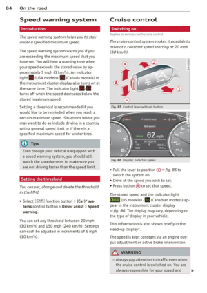
.. Press inward strongly on the left s ide of the
cap to remove it from the bumper
¢fig . 224 .
.. Screw the towing loop in the threaded open-
ing and tighten it until it stops
¢fig. 225.
Remove the towing loop when you are done
using it and place it back in the vehicle tool
kit. Install the cover in the bumper. Always
keep the towing loop in the vehicle.
A WARNING
If you do not screw the tow ing loop com
pletely, it could come out of the threaded
hole while the vehicle is being towed cau s
ing damage to the vehicle and possib le se
r ious personal inju ry.
Rear towing loop
Only install the rear towing loop when it is
needed.
F ig. 226 Rear bumper: cover
Fig. 2 27 Rear bumper: screwing in towing loop
There are threads located behind the right
side of the rear bumper where a towing loop
can be installed. The threads are located be
hind a cover.
Emergenc y situ ation s 2 79
.. Remove the tow ing loop from the vehicle
too l kit .
.. Press inward strongly to the button side of
the cap to remove it from the bumper
¢fig. 226.
.. Screw the towing loop in the threaded open
ing and tighten it unt il it stops. The indica
to r mark ing must be flush w ith th e bumper
¢ fig. 227 .
Remove the towing loop when you are done
using it and place it back in the ve hicle too l
ki t. Always keep the towing loop in the vehi
cle.
A WARNING
If yo u do not screw the towing loop com
p letely , it co uld come out of the t hreaded
hole while the vehicle is being towed caus
ing damage to the vehicle and possible se
rious pe rsonal injury.
loading the vehicle onto a flat bed truck
Fi g. 228 Ve hicle on flat bed tru ck
Front hook up
.. Align the vehicle with t he centerline of the
car car rier ramp .
.,. Attach the winch hook to the front towline
eye prev iously insta lled .
Rear hook up
.,. Align the vehicle with the center line of the
car carrier ramp .
.. Attach the winch hook to the re ar tow line
eye prev ious ly insta lled .
u,
"' "'
Page 282 of 306

280 Emergency situations
@ Tips
Check carefully to make sure the hook-up
is secure before moving the car up the flat
bed truck ramp.
Vehicle transport
Whenever you have your vehicle transported,
be sure to note the following:
(D Note
Mount the tie-down chains/cables over the
running surface (circumference) of the
tires. Never secure the vehicle by the axle,
the suspension struts or the front or rear
towline eye. For technical reasons, the
pressure in the suspension struts may
change during the transport and this will
adversely affect vehicle handling.
Lifting vehicle
Lifting with workshop hoist and with
floor jack
The vehicle may only be lifted at the lifting
points illustrated.
Fig. 229 Front lift in g po int
Fig. 230 Rear lifti ng point
., Read and heed WARNING c> &, .
~ N 0 6 .., (0
., Activate the vehicle jack mode* in the MMI:
!CARI function button > (Car)* systems con
trol button>
Servicing & checks> Air susp.:
jack mode > On.
., Locate lifting points ¢ fig . 229 and
¢fig . 230 .
., Adjust lifting arms of workshop hoist or
floor jack to match veh icle lifting points .
., Insert a rubber pad between the floor jack/
workshop hoist and the lifting points .
The vehicle jack mode* must be activated so
that the automat ic adjustment of the Adap
tive Ai r Suspens ion* does not make it more
difficult to raise the vehicle with the floor
jack .
If you must lift your vehicle with a floor jack
to work underneath, be sure the vehicle is
safely supported on stands intended for this
purpose.
Front lifting point
The lifting point is located on the floor pan re
inforcement about at the same level as the
jack mounting point
¢fig. 229. Do not lift
the vehicle at the vertical sill reinforcement .
Rear lifting point
The lifting point is located on the vert ical rein
forcement of the lower sill for the on-board
jack
c!;> fig. 230.
Lifting with vehicle jack
Refer to¢ page 268 .
A WARNING
-To reduce the risk of serious injury and
veh icle damage.
- Always lift the vehicle only at the spe
cial workshop hoist and floor jack lift
points illustrated¢
fig. 229 and
¢ fig. 230.
-Failure to lift the veh icle at these
points could cause the vehicle to tilt or
fall from a lift if there is a change in ve
hicle weight distribution and balance.
This might happen, for example, when
-
Page 283 of 306

heavy components such as the engi ne
b lock or transmiss ion are removed.
- W hen removing heavy components like
these, ancho r vehicle to hoist o r add cor
respond ing weig hts to ma inta in the cen
ter of g ravity . Otherwise, the vehicle
m ight tilt o r sli p off the hoist, causi ng
ser ious p erso na l in ju ry.
([) Note
-Be awa re of the fo llowing points befo re
li fting t he vehicle:
- The vehicle should never be lifted or
jacked up from underneath the engine oil pan, the transmission housing, the
front or rear axle or the body side
members. This could lead to serious
damage.
- To avoid damage to the underbody or
chassis frame , a rubber pad must be
i nserted between the floor jack and
the lift points.
- Before driving over a workshop hoist,
check that the veh icle weight does not
exceed the permissible lifting capacity
of the hoist.
- Before driving over a workshop hoist,
ensure that there is sufficient clear
ance between the hoist and low parts
of the vehicle.
Emergency situations 281
•
•
Page 284 of 306

282 Technical data
Technical data
Vehicle identification
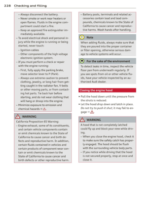
F ig. 23 1 Vehicle I dent ifica tion Num ber (VlN) pla te: lo·
cat ion on driver 's side dash pane l
XXXXX XX · X -XXXX XXX xx
r,"\__l f~ -11!111 · NII. ~ V!Hlll -llllll . NO.
IYP IT'fl'E
XXXXXXXX XX X XXXXXXXX
XXX XXX
XX XXXXXXX XX X X XX
XXX
KW XXX
®i ~~:f :l~~ XXXX XXX XXX
@+ ~~r= XXXX I XXXX XXX I XX M ,. AIIISl./ lflllllS
EOA 7D5 4 UB 6XM SSG 5RW
2E H JDZ llB l AS lBA
3FC 5MU 7Xl
FO A
9G3 OG7 O
YH OJF
TL6 3
KA BEH
UlA X9B QZ 7
l XW
8Q3 9Q8 82 4 020
7T6 CV 7 7KO 4X3 2K2
3L4 4 KC 3YO 4I3 502
lS A 7GB Q1A 4GQ
XX X
XX X XX X XXXX
Fig. 23 2 The ve hicle identi ficat ion label -inside the
luggage co mpa rtmen t
Vehicle Identification Number (VlN )
The Ve hicle Identific ation Number is located
in different p laces:
- under the w indshield on the driver's s ide
~fig . 231.
- in the MMI : Select: Function button ICAR I >
(Car) * syst ems > VIN number .
-on the veh icle identification label.
Vehicle identification label
The vehicle identification labe l is located in
the luggage compartment in the spare wheel
well. T
he label ~
fig. 232 shows the fo llowing vehi
cle data:
(D Vehicle Iden tificat io n Num ber (V IN)
@ . Vehicle type, engine o utput, transmission
® Engine and transm iss ion code
@ Pain t number and inte rior
® Optional equipment numbers
T he information of the vehicle identification
label can also be found i n your Warranty
&
Maintenance booklet.
Safety compliance sticker
The safety compliance sticker is your assur
ance that yo ur new veh icle complies with all
applicable Federa l Motor Vehicle Safety
Standards which we re in effect at the time the
vehicle was manufactured. You can find this
sticker on the door jamb on the driver's side.
It shows the mo nth and year of production
and the vehicle ident ificat io n number of your
vehicle (perfo rat io n) as well as the Gross Ve hi
cl e Weig ht Rating (GVWR) a nd the Gross Ax le
Weig ht Rating (GAWR) .
High voltage warning label
The high voltage warning label is located in
the engine compartment next to the engine
hood re lease . The spar k ign it ion sys tem com·
plies wi th the Ca nadian standard IC ES-002.
Weights
Gross Vehicle Weight Rating
The Gross Vehicle We ight Rat ing (GVWR), and
t h e Gross Axle Weight Rat ing (GAWR) for
fron t and rear are liste d on a sticker on the
doo r jamb on the d river's side .
T he Gross Vehicle We ight Rat ing includes the
weight of the bas ic vehicle plus f ull fuel tank,
o il and coo la nt, plus max imum load, which in
cl udes passe nger we igh t (150 l bs/68 kg per
designate d sea ting posi tion) an d lugg age
weight ~&. - .,.
Page 285 of 306

Gross Axle Weight Rating
The Gross Axle Weight Rating is the maximum
l oad that can be applied at each axle of the
vehicle
c::> &. .
Vehicle capacity weight
The vehicle capac ity we ight (max. load) is list
ed eithe r on the driver's side B-pillar or inside
the fuel filler flap.
& WARNING
-
- The actual Gross Axle Weight Rating at
the front and rear axles shou ld not ex
ceed the perm iss ible weights, and their
combination must not exceed the Gross
Vehicle Weight Rat ing.
Dimensions
Length in (mm)
Width in (mm)
Width (across mir rors) in (mm)
He ight (unloaded)a) in (mm)
Turn ing circle diameter
ft (m)
Techn ical data 283
-Exceeding perm iss ible weight ratings can
result in vehicle damage, acc idents and
personal injury.
([) Note
-The vehicle capacity weight figures apply
when the load is d istr ibuted evenly in the
vehicle (passengers and luggage). When
transport ing a heavy load in the luggage
compartment, carry the load as near to
the rear axle as poss ible so that the vehi
cle's handling is not impaired.
- Do not exceed the maximum permissible
axle loads or the maximum gross veh icle
we ight. Always remember that the vehi
cle's handling will be affected by the ex
tra load. Therefore, adjust your speed ac
cordingly.
- Always observe local regulations .
A7 S7
19S.6 (4969) 19S.6 (4969)
75 .2 (1911) 75 .2 (1911)
84.2 (2139) 84.2 (2139)
55 .9 (1420) 55 .9 (1420)
39.0 (1 1.9) 39.0 ( 11.9)
•
•
aJ The height of the veh icle depends o n the t ires and the suspe nsion .
When driving up steep ramps, on rough roads,
over curbs, etc . it is im portant to remember
that some parts of your ve hicle, such as spoil-
Capacities
Fuel tank : total capacity
Windshield flu id container
Windshield and headlight washer fluid container* ers o
r exhaust system components, may be
close to the ground. Be carefu l not to damage
them.
gal (liters) approx. 19.8 (7S.0)
quarts (liters) approx. 3.7 (3.5)
quarts (liters) approx.
S.2 (4.9)
Page 286 of 306
284 Technical data
Gasoline engines
A7 3.0, 6 cylinder
Maximum output SAE net hp@rpm 310@ 5500 - 6500
Max imum torque SAE net lb-ft@ rpm 3
25@ 2900 -4500
Displacement CID (cm
3
) 182 (2995)
E ngine oil with f ilter change q
uarts ( lite rs) 7.2 (6.8)
Fuel
Premium unleaded (91 AKI) , ¢page 218, Gasoline
57 4.0, 8 cylinder
Maximum output SAE net hp@rpm 420 @ 5500 - 6400
Maximum torque SA E net lb -ft@ rpm 406 @ 1 400 -5200
Displacement CID (cm
3
) 243 .7 (3993)
E ngine oil with filter change qu
arts ( lite rs) 8.8 (8 .3)
Fuel
Premium unleaded (91 AKI) , ¢page 218, Gasoline
Diesel engine
A7 3.0 TDI, 6 cylinder
Maximum outpu t SA E n et hp@rpm 240@ 3 500 - 37 50
Maximum torque SAE net lb-ft@ rpm 428@ 1750 -2250
Di spla cement C
ID (cm
3
) 18 1 (29 67)
Engine oil with filter change quarts (li ters) 6.8 (6.4)
F uel
ULSD-Die sel No. 2 , ¢ page 219, Diesel fuel
Page 287 of 306

Consumer Information
Warranty coverages
Your Audi is covered by the following war
ranties :
- New Vehicle Limited Warranty
- Limited Warranty Against Corrosion Perfo-
ration
- Emissions Control System Warranty
- Emissions Performance Warranty
- California Emissions Control Warranty (USA
vehicles only)
- California Emissions Performance Warranty
(USA vehicles only)
Detailed information regarding yo ur warran
ties can be found in your
Warranty & Mainte
nance booklet .
Operating your vehicle
outside the U.S.A. or
Canada
Government regulations in the United States
and Canada require that automobiles meet
specific emission regulations and safety
standards. Therefore, veh icles built for the
U.S.A. and Canada differ from vehicles sold in
other countries .
I f you p lan to take your vehicle outside the
continental limits of the United States or Can
ada, there is the possibility that:
- unleaded fuels for vehicles with cata lytic
converter may not be available;
- fuel may have a considerably lower octane
rating . Improper fuel may cause engine
damage;
- service may be inadequate due to lack of
proper service facilities, tools or testing
equipment;
- replacement parts may not be readily availa
ble.
- Navigation systems for vehicles built for the
U.S.A. and Canada will not necessari ly work
in Europe, and may not work in other coun
tries outside North America .
Consumer Information 285
@ Note
Audi cannot be responsible for mechanical
damage that could result from inadequate
fuel, serv ice or parts availab ility.
Audi Service Repair
Manuals and Literature
Audi Offic ial Factory Service Manuals and Lit
erature are published as soon as possible after
model introduct ion. Service manuals and lit
erat ure are available to order from the Audi
T echnical Literature Ordering Center at:
www.audi.techliterature.com
Maintenance
' General
Your vehicle has been designed to help keep
maintenance requirements to a m inimum.
However, a certain amount of regular mainte
nance is still necessary to assure your vehicle's
safety, economy and reliability . For detailed
vehicle maintenance consult your Warranty
&
Maintenance booklet.
Under difficult operating conditions , for ex
ample at extremely low outside temperatures,
in very dusty regions, when towing a trailer
very frequently, etc., some serv ice work
shou ld be pe rformed between the intervals
specified. This applies particularly to:
- oil changes, and
- cleaning or replacing the air filter.
® For the sake of the environment
By regularly maintaining your veh icle, you
help make sure that emission standards
are maintained, thus min imiz ing adverse
effects on the environment .
Important considerations for you and
your vehicle
The increasing use of electronics, sophistica t
ed fuel injection and emission contro l sys-
tems, and the genera lly increasing technica l ..,_
•
•
Page 288 of 306

28 6 Con sum er Inf ormation
comp lexity of today's automobi les, have
steadi ly reduced the scope of maintenance
and repairs which can be carried out by vehicle
owners.
Also, s afety an d e nvir onm ent al con
cerns place very strict limits on the nature of repairs and adjustments to engine and trans
miss ion pa rts which an owner can perform .
Maintenance, adjustments and repa irs usua lly
require special tools, testing devices and oth
er equipment avai lab le to specially trained
workshop personnel in order to assure proper
performance, reliab ility and safety of the vehi
cle and its many systems .
Improper ma intenance, adjustments and re
pa irs can impair the operation and reliab ility
of your vehicle and even void your vehicle war ranty. Therefo re , proof of servici ng in accord
ance w it h the ma intenance sched ule may be a
condition for upholding a possible warranty
claim made within the warran ty period.
Above all, operational safety can be adve rsely
affected, c reating unnecessary risks for you
and your passengers.
If in doubt about any serv icing, have it done
by your author ized Audi dealer or any other
p roperly equipped and qualified workshop .
We strong ly urge you to give your authorized
Audi dealer the opportunity to perform all
schedu led maintenance and necessary repairs .
Your dea ler has the facilities, or iginal parts
and tra ined spec ialists to keep your vehicle
running properly .
Performing lim it e d m aint en anc e y ourself
The fo llowing pages describe a limited num
ber of procedures which can be performed on
you r vehicle with ordinary too ls, shou ld the
need arise and trained personnel be unavaila
ble. Before performing any of these proce
dures, always thoroughly read all of the app li
cable text and ca refully follow the instruc
tions given. Always rigorously obse rve the
WARNINGS p rovided .
Before you ch eck anything in th e engin e
compartme nt, alway s read an d heed all WARNINGS
¢ & a
nd ¢ & in Working in the
engine comportment on page
22 7 .
A WARNING
--Serious personal in jury may occur as a re-
sult of improperly performed mainte nance, adjustments or repa irs.
- Always be extremely careful when work
ing on the vehicle. Always follow com
monly accepted safety pract ices and gen
eral common sense. Never r isk personal
in jur y.
- Do not attempt any of the maintenance,
checks or repairs descr ibed o n the fol
lowing pages if you are not fu lly fam iliar
with these or other procedures with re spect to the ve hicl e, or are uncerta in how
to proceed .
- Do not do any work withou t the proper
too ls and equipment . Have the necessary
work done by your authorized A udi deal
er or anothe r properly equipped and
qualified workshop.
- The engine compar tment o f any motor
vehicle is a potentially hazardous area. Never reach into the area around or
touch the rad iator fan. It is temperature
control led and can sw itch on suddenly -
even when the engine is off . The radiator
fan switches on automatically when the
coo lant reaches a ce rtain temperature
and will cont inue to ru n until the coo lant
tempera ture drops.
- Always sw itch off the ignition before any
one gets under the vehicle.
- Always support your veh icle with safety
s tands if it is necessary to work under
neath the vehicle. The j ack s upp lied with
the vehicle is not adequate for this pur
pose and cou ld co llapse causing serio us
pe rsonal injury .
- If you must work underneath the vehicle
wit h the wheels on the ground, a lways
make sure the vehicle is on leve l ground,
that the wheels are a lways secure ly
blocked and that t he engine cannot be
started .